EP0468263A1 - Raquette pour jeux de balles, en particulier raquette de tennis - Google Patents
Raquette pour jeux de balles, en particulier raquette de tennis Download PDFInfo
- Publication number
- EP0468263A1 EP0468263A1 EP91111309A EP91111309A EP0468263A1 EP 0468263 A1 EP0468263 A1 EP 0468263A1 EP 91111309 A EP91111309 A EP 91111309A EP 91111309 A EP91111309 A EP 91111309A EP 0468263 A1 EP0468263 A1 EP 0468263A1
- Authority
- EP
- European Patent Office
- Prior art keywords
- racket
- handle
- shaft
- racket according
- articulation
- Prior art date
- Legal status (The legal status is an assumption and is not a legal conclusion. Google has not performed a legal analysis and makes no representation as to the accuracy of the status listed.)
- Granted
Links
Images

Classifications
-
- A—HUMAN NECESSITIES
- A63—SPORTS; GAMES; AMUSEMENTS
- A63B—APPARATUS FOR PHYSICAL TRAINING, GYMNASTICS, SWIMMING, CLIMBING, OR FENCING; BALL GAMES; TRAINING EQUIPMENT
- A63B49/00—Stringed rackets, e.g. for tennis
- A63B49/02—Frames
-
- A—HUMAN NECESSITIES
- A63—SPORTS; GAMES; AMUSEMENTS
- A63B—APPARATUS FOR PHYSICAL TRAINING, GYMNASTICS, SWIMMING, CLIMBING, OR FENCING; BALL GAMES; TRAINING EQUIPMENT
- A63B49/00—Stringed rackets, e.g. for tennis
- A63B49/02—Frames
- A63B49/08—Frames with special construction of the handle
-
- A—HUMAN NECESSITIES
- A63—SPORTS; GAMES; AMUSEMENTS
- A63B—APPARATUS FOR PHYSICAL TRAINING, GYMNASTICS, SWIMMING, CLIMBING, OR FENCING; BALL GAMES; TRAINING EQUIPMENT
- A63B60/00—Details or accessories of golf clubs, bats, rackets or the like
- A63B60/0081—Substantially flexible shafts; Hinged shafts
-
- A—HUMAN NECESSITIES
- A63—SPORTS; GAMES; AMUSEMENTS
- A63B—APPARATUS FOR PHYSICAL TRAINING, GYMNASTICS, SWIMMING, CLIMBING, OR FENCING; BALL GAMES; TRAINING EQUIPMENT
- A63B60/00—Details or accessories of golf clubs, bats, rackets or the like
- A63B60/54—Details or accessories of golf clubs, bats, rackets or the like with means for damping vibrations
-
- A—HUMAN NECESSITIES
- A63—SPORTS; GAMES; AMUSEMENTS
- A63B—APPARATUS FOR PHYSICAL TRAINING, GYMNASTICS, SWIMMING, CLIMBING, OR FENCING; BALL GAMES; TRAINING EQUIPMENT
- A63B49/00—Stringed rackets, e.g. for tennis
- A63B49/02—Frames
- A63B49/03—Frames characterised by throat sections, i.e. sections or elements between the head and the shaft
-
- A—HUMAN NECESSITIES
- A63—SPORTS; GAMES; AMUSEMENTS
- A63B—APPARATUS FOR PHYSICAL TRAINING, GYMNASTICS, SWIMMING, CLIMBING, OR FENCING; BALL GAMES; TRAINING EQUIPMENT
- A63B60/00—Details or accessories of golf clubs, bats, rackets or the like
- A63B60/002—Resonance frequency related characteristics
-
- A—HUMAN NECESSITIES
- A63—SPORTS; GAMES; AMUSEMENTS
- A63B—APPARATUS FOR PHYSICAL TRAINING, GYMNASTICS, SWIMMING, CLIMBING, OR FENCING; BALL GAMES; TRAINING EQUIPMENT
- A63B60/00—Details or accessories of golf clubs, bats, rackets or the like
- A63B60/06—Handles
-
- A—HUMAN NECESSITIES
- A63—SPORTS; GAMES; AMUSEMENTS
- A63B—APPARATUS FOR PHYSICAL TRAINING, GYMNASTICS, SWIMMING, CLIMBING, OR FENCING; BALL GAMES; TRAINING EQUIPMENT
- A63B60/00—Details or accessories of golf clubs, bats, rackets or the like
- A63B60/06—Handles
- A63B60/08—Handles characterised by the material
-
- A—HUMAN NECESSITIES
- A63—SPORTS; GAMES; AMUSEMENTS
- A63B—APPARATUS FOR PHYSICAL TRAINING, GYMNASTICS, SWIMMING, CLIMBING, OR FENCING; BALL GAMES; TRAINING EQUIPMENT
- A63B60/00—Details or accessories of golf clubs, bats, rackets or the like
- A63B60/06—Handles
- A63B60/10—Handles with means for indicating correct holding positions
Definitions
- the invention relates to a racket for ball games, in particular a tennis racket, with a covering provided in a tensioning frame made of a profiled bar, a heart zone adjoining this and with a handle on a racket neck in the longitudinal axis of the racket, which preferably forms a line of symmetry, the free end of the handle being separated from one Grip forehead is determined.
- Tennis rackets of this type can be found, for example, in DE-OS 30 18 354. Clamped in the area of the handle, a natural frequency of 25 to max. 50 Hz detected; unstrung tennis rackets generally show slightly higher values. The frequency of the overall racket / stringing system has a significant influence on the hand playing with it and thus also on the creation of the so-called tennis arm.
- the inventor has set itself the goal of intercepting or at least alleviating the influences acting on the hand of the player of such a racket, in particular the so-called shock shock that occurs when contacting the ball, without giving up the advantages of a very rigid frame, such as, for example, in the case of Clubs according to DE-PS 33 43 898 are given.
- the racket has an articulation point between the heart zone and the forehead of the handle and the articulation axis runs parallel to the covering, that is to say in the plane determined by the stenter frame.
- the emerging pivot point or near this pivot point in the racket neck or in the handle there is an elastic joint which changes the frequency behavior of the racket and compensates for the shock.
- the pivot point of the racket when hitting a ball is referred to in technical terms as "pivot pivot point".
- pivot point There are no forces at this point, but there is torque around it.
- the club influences forces in the direction of the incoming ball in the event of a ball impact.
- forces act in the opposite direction. Therefore, a racket tries to tip out of the hand on a forehand stroke, whereas it hits the palm of the hand on a backhand stroke. This may be the reason why players with a so-called tennis arm can hit the forehand relatively painlessly, but that more pain occurs on a backhand.
- the elastic joint can thus be arranged according to the invention in a range of 60 to 200 mm from the handle front. This is also the area in which that pivot lies.
- the joint is formed by an elastic block of material - a rubber block - which is preferably vulcanized onto both sides of plates of the handle parts and connect two handle parts of the handle.
- the articulation point is a web part of the handle or the racket neck, which is delimited on both sides by groove-like molding grooves.
- the width of this groove or groove measured in the longitudinal axis of the racket can be up to 100 mm, but will generally be considerably shorter.
- the depth of the web part corresponds approximately to the depth of the molded channel, which requires the shaft cross section to be divided into three sections of approximately the same width.
- the two grooves of this embodiment are preferably filled with a molding compound of low flexural rigidity, in particular when the two grooves are provided in the grip area and must be covered by the grip leather.
- the object of the invention is also achieved by a racket with a plurality of parallel axes of adjacent articulation points directed transversely to the longitudinal axis of the racket.
- the deflection in the elastic region of the racket, which is firmly clamped on the handle up to the first joint, under the action of a force that acts headwards at a distance of 400 mm from the joint axis, should be 1.2 to 9 times as large as the deflection of a jointless - otherwise but appropriately designed - racket with firm clamping on the handle up to the hinge axis.
- the joint location (s) reduces the frequency of a racket firmly clamped to the first joint on the handle by v12 to vif] compared to an identical racket without a joint location.
- the intermediate layer - seen in cross section - can also consist of several strips or strands which leave empty spaces or gaps between them.
- a round strand is provided which keeps the two associated shaft rods at a distance and the remaining sections of the shaft gap free.
- the elastic mass rests on both sides of the surfaces delimiting the shaft gap and that the shaft rods can be moved - at least partially - laterally relative to one another in the direction of impact.
- the handle is separated in the case of a symmetrical racket construction parallel to the striking direction or perpendicular to the striking surface and preferably along the longitudinal axis of the racket. If the separating shaft gap lies outside the center line, is curved, oblique or jagged, the damping results that can be achieved are not quite as good, but are still acceptable. According to a further feature of the invention, the i.w. rectangular cross-section of the shaft gap linear in the plane or surface, but the cross-section can also be wave-shaped or jagged.
- the elastic connecting elements of properly separated shaft or handle bars can - e.g. B. from a silicone rubber layer - be continuous. However, it is also conceivable to arrange them in a punctiform manner or only in strip form, for example at the cutting edge or the gap ends. These connecting elements can be made from pieces of tubing, round rubber cords or otherwise resilient. A partial opening, for example slots, which can also be unfilled, is also conceivable; a firm connection could only remain at the end of the handle and the slot above could contain a damping material.
- the surface is curved in cross section, and several surfaces can be assigned to one another.
- linear or curved flat bars made of elastic mass are used which, as described, can completely or only partially fill the shaft gap.
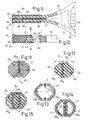
- a tennis racket 10 shown by way of example in FIGS. 1 to 4 has an oval racket head or clamping frame 14 formed by a correspondingly curved profile bar 12.
- the profile rod 12 of the club head 14 ends on both sides of the longitudinal axis M in - profile arms 16 which laterally delimit an open heart zone H, which are connected by a frame web 18 and merge into a club neck 19.
- the racket head 14 and the frame web 18 determine a stringing surface Q from cross strings 24 and these cross-stringing longitudinal strings 25.
- the preferred point of impact A for a tennis ball, not shown, in FIG. 1 lies approximately at the intersection of the racket longitudinal axis M with the section line 111-111 and in FIG. 2 approximately in a line K.
- the club head 14 or its hollow profile rod 12 is i.w. of elongated oval cross section, the side walls 26 of which run at an inner distance a of, for example, 8 mm (outer width m about 10 mm) and merge into curved sections 27 with an inner profile height b of 20 mm and an outer profile height n of about 25 mm here.
- This profile rod 12 is formed from a tube-like blank 30, in which 27 longitudinal fiber strands 31 are arranged in the curved sections.
- the ends of the blank 30 are brought together on the bat neck 19 in such a way that two chambers 29 are formed in this and in the handle 20. 4, the two ends of the blank 30 form the octagonal cross section of the handle 20.
- the handle 20 is made of two parts 32, 32a, which are connected at a distance e by an elastic intermediate piece 34.
- the latter comprises two transverse plates 36 made of metal or another suitable material and a rubber block 38 which is vulcanized onto them.
- the distance of this hinge axis B from the end 15 of the club head 14 is denoted by g.
- the articulation point shown in FIGS. 6, 7 is defined by grooves 40 of the greatest width z formed on both sides in the handle 20 - tapering towards the handle axis M.
- the grooves 40 are filled, for example, by plastic blocks 42 with low bending stiffness.
- the depth i of the grooves 40 is somewhat shorter in FIG. 7 than the thickness c of a stopped intermediate web 44 of the handle 20; the surfaces of the intermediate web 44 each form the deepest groove 41.
- longitudinal strands 31 of the blank 30 are placed around the grooves 40, that is to say not interrupted at the joint point.
- the deflection is due to an acting force due to the lower moment of inertia in the cross-section of the web per unit length, about 4.3 times as high as the deflection with a full cross-section of the handle if the modulus of elasticity is assumed to be unchanged otherwise the deflection is inversely proportional to the product of the moment of inertia x modulus of elasticity.
- the web thickness c is only a third of the thickness h of the handle 20, the corresponding value is 12.5 and finally becomes 20 times as high as a quarter.
- the articulation point 34 must act fairly elastic in order to bring about small frequency changes. This will be explained using an example of the embodiment according to FIGS. 5 and 6.
- the thickness c of the web 44 should be half the handle thickness h of the tennis racket 10, the width z is 20 mm.
- the distance t from the handle end 23 is set at 120 mm.
- the ball hits the covering Q at point A, which in the selected example is 400 mm away from the articulation axis B.
- the moment of inertia for the full grip cross section is unchanged for all racket cross sections - that is to say over the entire racket length - no torsional moments occur and the modulus of elasticity remains constant.
- the calculation shows that the deflection of the tennis racket 10 with the described ben articulation point 34 under the effective ball force is 1.22 times as high as that of an identical racket without a joint.
- the frequency of the tennis racket 10 would then change with the reciprocal of the root of the deflection. If the tennis racket 10 had a frequency of 80 Hz, the racket provided with this joint would have a frequency of 80 x 1/1 . Show 22 Hz, i.e. 72.5 Hz.
- Another example should show how a larger frequency reduction is possible.
- the web height c is chosen with a quarter of the handle thickness h.
- the width z is 100 mm. Otherwise, the data from the first example apply.
- the required deflection would be six times as large and the desired frequency root six times lower, i.e. instead of 80 Hz only 33 Hz.
- This frequency relates to a tennis racket 10 firmly clamped to the handle 20.
- the racket neck 19 and the subsequent shaft of the handle 20 are symmetrically divided in the direction of the longitudinal axis M of the racket, ie each of the profile arms 16 continues with its own shaft rod 46 in the handle 20, with both shaft rods 46 a together determine the outer contour of a grip shaft 46 and delimit between them a shaft gap 48 which receives an elastic intermediate layer 50 in FIG. 9 and determines a plane E which crosses the covering surface Q approximately in FIG. 11 to 14.
- the shaft rods 46 a - apart from the articulation point 40/44 - are symmetrical solid profiles with an interposed strip of elastic mass as a filling intermediate layer 50 in the shaft gap 48 which is linear in cross section here, whereas FIG. 12 Shaft rods 46 b , 46 c with different cross-sections can be seen with an undulating shaft gap 48 c between them - at different distances f, g from the side contours 52 - which is completely filled by the elastic intermediate layer 50 c .
- FIG. 13 illustrates a handle 20 with a hollow profile divided symmetrically in the plane E into shaft rods 46 d with an elastic round strand 50 d .
- the embodiment of FIG. 14 corresponds to that of FIG. 11 with the difference that the shaft rods 46 e are hollow profiles, each with an all-around limited profile chamber 47.
- FIG. 15 shows a three-part handle shaft 46 f consisting of two flank bars 54 and a core or center bar 55, between which intermediate layers 50 k curved in the shape of a circle can be seen.
- two curved surfaces F can be seen here.
Landscapes
- Health & Medical Sciences (AREA)
- General Health & Medical Sciences (AREA)
- Physical Education & Sports Medicine (AREA)
- Golf Clubs (AREA)
- Laminated Bodies (AREA)
- Vibration Dampers (AREA)
- Compositions Of Macromolecular Compounds (AREA)
- Polyesters Or Polycarbonates (AREA)
- Blow-Moulding Or Thermoforming Of Plastics Or The Like (AREA)
- Vibration Prevention Devices (AREA)
- Prostheses (AREA)
Applications Claiming Priority (4)
| Application Number | Priority Date | Filing Date | Title |
|---|---|---|---|
| DE4023906 | 1990-07-27 | ||
| DE4023906 | 1990-07-27 | ||
| DE4106067A DE4106067A1 (de) | 1990-07-27 | 1991-02-27 | Schlaeger fuer ballspiele, insbesondere tennisschlaeger |
| DE4106067 | 1991-02-27 |
Publications (2)
| Publication Number | Publication Date |
|---|---|
| EP0468263A1 true EP0468263A1 (fr) | 1992-01-29 |
| EP0468263B1 EP0468263B1 (fr) | 1995-05-24 |
Family
ID=25895417
Family Applications (1)
| Application Number | Title | Priority Date | Filing Date |
|---|---|---|---|
| EP91111309A Expired - Lifetime EP0468263B1 (fr) | 1990-07-27 | 1991-07-08 | Raquette pour jeux de balles, en particulier raquette de tennis |
Country Status (9)
| Country | Link |
|---|---|
| EP (1) | EP0468263B1 (fr) |
| JP (1) | JP3129772B2 (fr) |
| CN (1) | CN1064414A (fr) |
| AT (1) | ATE122907T1 (fr) |
| CA (1) | CA2047076A1 (fr) |
| DE (2) | DE4106067A1 (fr) |
| DK (1) | DK0468263T3 (fr) |
| ES (1) | ES2076423T3 (fr) |
| MY (1) | MY107222A (fr) |
Families Citing this family (7)
| Publication number | Priority date | Publication date | Assignee | Title |
|---|---|---|---|---|
| DE4200596A1 (de) * | 1991-02-27 | 1993-02-25 | Siegfried Kuebler | Schlaeger fuer ballspiele, insbesondere tennisschlaeger |
| DE4410664C2 (de) * | 1994-01-27 | 1996-10-17 | Franz Voelkl Gmbh & Co Ski Ten | Ballspielschläger |
| DE19825075A1 (de) * | 1998-06-04 | 2000-02-10 | Peter Weidenschlager | Tennisschläger |
| DE10304797B4 (de) * | 2003-02-05 | 2007-02-01 | Völkl Tennis GmbH | Ballspielschläger, insbesondere Tennisschläger |
| JP2013022361A (ja) | 2011-07-25 | 2013-02-04 | Dunlop Sports Co Ltd | ラケットフレーム |
| US20220355166A1 (en) * | 2021-05-06 | 2022-11-10 | Wilson Sporting Goods Co. | Racquet having an improved handle assembly |
| JP7748665B2 (ja) * | 2021-07-30 | 2025-10-03 | 住友ゴム工業株式会社 | ラケット |
Citations (7)
| Publication number | Priority date | Publication date | Assignee | Title |
|---|---|---|---|---|
| GB458103A (en) * | 1935-06-12 | 1936-12-14 | William Henri Kerr | Improvements in handles for rackets used in playing games |
| US4082273A (en) * | 1976-02-19 | 1978-04-04 | The Ellzey Company | Striking implements |
| FR2547506A1 (fr) * | 1983-06-17 | 1984-12-21 | Blondy Jacques | Raquette de tennis |
| DE3712772A1 (de) * | 1986-04-18 | 1987-10-22 | Dunlop Ltd | Ballspiel-schlaeger (racket) mit verbesserten spieleigenschaften |
| DE3627997A1 (de) * | 1986-08-21 | 1988-03-03 | Lo Kun Nan | Schlaegerrahmen aus verbundwerkstoff |
| DE3706554A1 (de) * | 1987-02-28 | 1988-09-08 | Anton Ing Grad Pfeifer | Haltegriff fuer tennisschlaeger mit integriertem hydraulischen stossdaempfer |
| US4811947A (en) * | 1986-02-19 | 1989-03-14 | Yamaha Corporation | Vibration absorber for a racket |
Family Cites Families (1)
| Publication number | Priority date | Publication date | Assignee | Title |
|---|---|---|---|---|
| DE1684290U (de) * | 1954-07-03 | 1954-09-30 | Adolf Maedler | Schlaeger fuer federballspiel. |
-
1991
- 1991-02-27 DE DE4106067A patent/DE4106067A1/de not_active Withdrawn
- 1991-07-08 AT AT91111309T patent/ATE122907T1/de not_active IP Right Cessation
- 1991-07-08 EP EP91111309A patent/EP0468263B1/fr not_active Expired - Lifetime
- 1991-07-08 DK DK91111309.0T patent/DK0468263T3/da active
- 1991-07-08 ES ES91111309T patent/ES2076423T3/es not_active Expired - Lifetime
- 1991-07-08 DE DE59105564T patent/DE59105564D1/de not_active Expired - Fee Related
- 1991-07-15 CA CA002047076A patent/CA2047076A1/fr not_active Abandoned
- 1991-07-19 MY MYPI91001302A patent/MY107222A/en unknown
- 1991-07-25 JP JP03186038A patent/JP3129772B2/ja not_active Expired - Fee Related
- 1991-07-27 CN CN91105078A patent/CN1064414A/zh active Pending
Patent Citations (7)
| Publication number | Priority date | Publication date | Assignee | Title |
|---|---|---|---|---|
| GB458103A (en) * | 1935-06-12 | 1936-12-14 | William Henri Kerr | Improvements in handles for rackets used in playing games |
| US4082273A (en) * | 1976-02-19 | 1978-04-04 | The Ellzey Company | Striking implements |
| FR2547506A1 (fr) * | 1983-06-17 | 1984-12-21 | Blondy Jacques | Raquette de tennis |
| US4811947A (en) * | 1986-02-19 | 1989-03-14 | Yamaha Corporation | Vibration absorber for a racket |
| DE3712772A1 (de) * | 1986-04-18 | 1987-10-22 | Dunlop Ltd | Ballspiel-schlaeger (racket) mit verbesserten spieleigenschaften |
| DE3627997A1 (de) * | 1986-08-21 | 1988-03-03 | Lo Kun Nan | Schlaegerrahmen aus verbundwerkstoff |
| DE3706554A1 (de) * | 1987-02-28 | 1988-09-08 | Anton Ing Grad Pfeifer | Haltegriff fuer tennisschlaeger mit integriertem hydraulischen stossdaempfer |
Also Published As
| Publication number | Publication date |
|---|---|
| MY107222A (en) | 1995-10-31 |
| CA2047076A1 (fr) | 1992-01-28 |
| DE4106067A1 (de) | 1992-01-30 |
| ES2076423T3 (es) | 1995-11-01 |
| ATE122907T1 (de) | 1995-06-15 |
| JP3129772B2 (ja) | 2001-01-31 |
| JPH04236973A (ja) | 1992-08-25 |
| DE59105564D1 (de) | 1995-06-29 |
| EP0468263B1 (fr) | 1995-05-24 |
| CN1064414A (zh) | 1992-09-16 |
| DK0468263T3 (da) | 1995-10-16 |
Similar Documents
| Publication | Publication Date | Title |
|---|---|---|
| DE3434898C2 (fr) | ||
| DE2546028A1 (de) | Tennisschlaeger | |
| DE3910890C2 (de) | Schläger für Ballspiele, insbes. Tennisschläger | |
| DE10308532B3 (de) | Schläger für Ballspiele | |
| EP0468263B1 (fr) | Raquette pour jeux de balles, en particulier raquette de tennis | |
| EP1557203B1 (fr) | Raquette pour jeux de balle et méthode de fabrication | |
| EP1557204B1 (fr) | Raquette pour jeux de balle et méthode de fabrication | |
| EP0397832B1 (fr) | Raquette pour jeux de balle | |
| EP1097730B1 (fr) | Raquette pour jeux de balles | |
| EP1452209B1 (fr) | Raquette pour jeux de balle | |
| DE4200596A1 (de) | Schlaeger fuer ballspiele, insbesondere tennisschlaeger | |
| DE9200284U1 (de) | Schläger für Ballspiele, insbesondere Tennisschläger | |
| DE4102901A1 (de) | Racket | |
| DE3702197A1 (de) | Tennisschlaeger | |
| DE102006004863B4 (de) | Schläger für Ballspiele | |
| DE2812647A1 (de) | Tennisschlaeger | |
| EP0310169B2 (fr) | Raquettes pour jeux de balles, en particulier raquettes de tennis | |
| DE4024988A1 (de) | Schlaeger fuer ballspiele | |
| EP2138207B1 (fr) | Batteur de jeux de balle | |
| DE69300098T2 (de) | Tennisschläger und dergleichen. | |
| DE3940294C1 (en) | Tennis racket with inclined strings - has strings threaded through edges of frame members to reduce risk of ball hitting frame | |
| EP1154822B1 (fr) | Raquette pour jeu de balle | |
| DE3211738A1 (de) | Tennisschlaeger | |
| AT408417B (de) | Ballschläger, insbesondere tennisschläger | |
| DE4203682A1 (de) | Ballspielschlaeger, insbesondere tennisschlaeger |
Legal Events
| Date | Code | Title | Description |
|---|---|---|---|
| PUAI | Public reference made under article 153(3) epc to a published international application that has entered the european phase |
Free format text: ORIGINAL CODE: 0009012 |
|
| AK | Designated contracting states |
Kind code of ref document: A1 Designated state(s): AT BE CH DE DK ES FR GB GR IT LI LU NL SE |
|
| 17P | Request for examination filed |
Effective date: 19920403 |
|
| 17Q | First examination report despatched |
Effective date: 19930614 |
|
| GRAA | (expected) grant |
Free format text: ORIGINAL CODE: 0009210 |
|
| AK | Designated contracting states |
Kind code of ref document: B1 Designated state(s): AT BE CH DE DK ES FR GB GR IT LI LU NL SE |
|
| PG25 | Lapsed in a contracting state [announced via postgrant information from national office to epo] |
Ref country code: GR Free format text: LAPSE BECAUSE OF FAILURE TO SUBMIT A TRANSLATION OF THE DESCRIPTION OR TO PAY THE FEE WITHIN THE PRESCRIBED TIME-LIMIT Effective date: 19950524 |
|
| REF | Corresponds to: |
Ref document number: 122907 Country of ref document: AT Date of ref document: 19950615 Kind code of ref document: T |
|
| ITF | It: translation for a ep patent filed | ||
| REF | Corresponds to: |
Ref document number: 59105564 Country of ref document: DE Date of ref document: 19950629 |
|
| GBT | Gb: translation of ep patent filed (gb section 77(6)(a)/1977) |
Effective date: 19950619 |
|
| ET | Fr: translation filed | ||
| REG | Reference to a national code |
Ref country code: DK Ref legal event code: T3 |
|
| REG | Reference to a national code |
Ref country code: ES Ref legal event code: FG2A Ref document number: 2076423 Country of ref document: ES Kind code of ref document: T3 |
|
| PLBE | No opposition filed within time limit |
Free format text: ORIGINAL CODE: 0009261 |
|
| STAA | Information on the status of an ep patent application or granted ep patent |
Free format text: STATUS: NO OPPOSITION FILED WITHIN TIME LIMIT |
|
| 26N | No opposition filed | ||
| PGFP | Annual fee paid to national office [announced via postgrant information from national office to epo] |
Ref country code: SE Payment date: 19960701 Year of fee payment: 6 |
|
| PGFP | Annual fee paid to national office [announced via postgrant information from national office to epo] |
Ref country code: NL Payment date: 19960709 Year of fee payment: 6 |
|
| PGFP | Annual fee paid to national office [announced via postgrant information from national office to epo] |
Ref country code: AT Payment date: 19960715 Year of fee payment: 6 |
|
| PGFP | Annual fee paid to national office [announced via postgrant information from national office to epo] |
Ref country code: CH Payment date: 19960722 Year of fee payment: 6 |
|
| PGFP | Annual fee paid to national office [announced via postgrant information from national office to epo] |
Ref country code: ES Payment date: 19960723 Year of fee payment: 6 |
|
| PGFP | Annual fee paid to national office [announced via postgrant information from national office to epo] |
Ref country code: LU Payment date: 19960801 Year of fee payment: 6 |
|
| PGFP | Annual fee paid to national office [announced via postgrant information from national office to epo] |
Ref country code: BE Payment date: 19960911 Year of fee payment: 6 |
|
| REG | Reference to a national code |
Ref country code: CH Ref legal event code: PUE Owner name: SIEGFRIED KUEBLER TRANSFER- WILSON SPORTING GOODS Ref country code: CH Ref legal event code: NV Representative=s name: PATENTANWALTSBUERO FELDMANN AG |
|
| REG | Reference to a national code |
Ref country code: GB Ref legal event code: 732E |
|
| REG | Reference to a national code |
Ref country code: FR Ref legal event code: TP |
|
| PGFP | Annual fee paid to national office [announced via postgrant information from national office to epo] |
Ref country code: DK Payment date: 19970120 Year of fee payment: 6 |
|
| REG | Reference to a national code |
Ref country code: ES Ref legal event code: PC2A |
|
| PG25 | Lapsed in a contracting state [announced via postgrant information from national office to epo] |
Ref country code: LU Free format text: LAPSE BECAUSE OF NON-PAYMENT OF DUE FEES Effective date: 19970708 Ref country code: DK Free format text: LAPSE BECAUSE OF NON-PAYMENT OF DUE FEES Effective date: 19970708 Ref country code: AT Free format text: LAPSE BECAUSE OF NON-PAYMENT OF DUE FEES Effective date: 19970708 |
|
| REG | Reference to a national code |
Ref country code: DK Ref legal event code: EBP |
|
| PG25 | Lapsed in a contracting state [announced via postgrant information from national office to epo] |
Ref country code: SE Effective date: 19970709 Ref country code: ES Free format text: LAPSE BECAUSE OF THE APPLICANT RENOUNCES Effective date: 19970709 |
|
| PG25 | Lapsed in a contracting state [announced via postgrant information from national office to epo] |
Ref country code: LI Free format text: LAPSE BECAUSE OF NON-PAYMENT OF DUE FEES Effective date: 19970731 Ref country code: CH Free format text: LAPSE BECAUSE OF NON-PAYMENT OF DUE FEES Effective date: 19970731 Ref country code: BE Free format text: LAPSE BECAUSE OF NON-PAYMENT OF DUE FEES Effective date: 19970731 |
|
| NLS | Nl: assignments of ep-patents |
Owner name: WILSON SPORTING GOODS COMPANY |
|
| BERE | Be: lapsed |
Owner name: WILSON SPORTING GOODS CO Effective date: 19970731 |
|
| PG25 | Lapsed in a contracting state [announced via postgrant information from national office to epo] |
Ref country code: NL Free format text: LAPSE BECAUSE OF NON-PAYMENT OF DUE FEES Effective date: 19980201 |
|
| REG | Reference to a national code |
Ref country code: CH Ref legal event code: PL |
|
| NLV4 | Nl: lapsed or anulled due to non-payment of the annual fee |
Effective date: 19980201 |
|
| EUG | Se: european patent has lapsed |
Ref document number: 91111309.0 |
|
| REG | Reference to a national code |
Ref country code: ES Ref legal event code: FD2A Effective date: 20001009 |
|
| REG | Reference to a national code |
Ref country code: GB Ref legal event code: IF02 |
|
| PGFP | Annual fee paid to national office [announced via postgrant information from national office to epo] |
Ref country code: DE Payment date: 20040609 Year of fee payment: 14 |
|
| PGFP | Annual fee paid to national office [announced via postgrant information from national office to epo] |
Ref country code: GB Payment date: 20040709 Year of fee payment: 14 Ref country code: FR Payment date: 20040709 Year of fee payment: 14 |
|
| PG25 | Lapsed in a contracting state [announced via postgrant information from national office to epo] |
Ref country code: IT Free format text: LAPSE BECAUSE OF NON-PAYMENT OF DUE FEES;WARNING: LAPSES OF ITALIAN PATENTS WITH EFFECTIVE DATE BEFORE 2007 MAY HAVE OCCURRED AT ANY TIME BEFORE 2007. THE CORRECT EFFECTIVE DATE MAY BE DIFFERENT FROM THE ONE RECORDED. Effective date: 20050708 Ref country code: GB Free format text: LAPSE BECAUSE OF NON-PAYMENT OF DUE FEES Effective date: 20050708 |
|
| PG25 | Lapsed in a contracting state [announced via postgrant information from national office to epo] |
Ref country code: DE Free format text: LAPSE BECAUSE OF NON-PAYMENT OF DUE FEES Effective date: 20060201 |
|
| GBPC | Gb: european patent ceased through non-payment of renewal fee |
Effective date: 20050708 |
|
| PG25 | Lapsed in a contracting state [announced via postgrant information from national office to epo] |
Ref country code: FR Free format text: LAPSE BECAUSE OF NON-PAYMENT OF DUE FEES Effective date: 20060331 |
|
| REG | Reference to a national code |
Ref country code: FR Ref legal event code: ST Effective date: 20060331 |