EP0468285B1 - Mit Federn unterstützte Anode - Google Patents
Mit Federn unterstützte Anode Download PDFInfo
- Publication number
- EP0468285B1 EP0468285B1 EP91111510A EP91111510A EP0468285B1 EP 0468285 B1 EP0468285 B1 EP 0468285B1 EP 91111510 A EP91111510 A EP 91111510A EP 91111510 A EP91111510 A EP 91111510A EP 0468285 B1 EP0468285 B1 EP 0468285B1
- Authority
- EP
- European Patent Office
- Prior art keywords
- sheet
- anode
- electrode
- sheets
- riser
- Prior art date
- Legal status (The legal status is an assumption and is not a legal conclusion. Google has not performed a legal analysis and makes no representation as to the accuracy of the status listed.)
- Expired - Lifetime
Links
Images


Classifications
-
- C—CHEMISTRY; METALLURGY
- C25—ELECTROLYTIC OR ELECTROPHORETIC PROCESSES; APPARATUS THEREFOR
- C25B—ELECTROLYTIC OR ELECTROPHORETIC PROCESSES FOR THE PRODUCTION OF COMPOUNDS OR NON-METALS; APPARATUS THEREFOR
- C25B11/00—Electrodes; Manufacture thereof not otherwise provided for
- C25B11/02—Electrodes; Manufacture thereof not otherwise provided for characterised by shape or form
-
- C—CHEMISTRY; METALLURGY
- C25—ELECTROLYTIC OR ELECTROPHORETIC PROCESSES; APPARATUS THEREFOR
- C25B—ELECTROLYTIC OR ELECTROPHORETIC PROCESSES FOR THE PRODUCTION OF COMPOUNDS OR NON-METALS; APPARATUS THEREFOR
- C25B1/00—Electrolytic production of inorganic compounds or non-metals
- C25B1/01—Products
- C25B1/24—Halogens or compounds thereof
- C25B1/26—Chlorine; Compounds thereof
- C25B1/265—Chlorates
Definitions
- the present invention relates generally to the art of electrolytic cells, and particularly to an expandable electrode for such cells.
- the present invention will be described with reference to an expandable anode for an electrolytic cell, although it will be apparent to those skilled in the art that the principles of the present invention are also applicable to the construction of an expandable cathode.
- a cathode may have an overall height of about two feet.
- the cathode which can as an example be a steel screen, may become misshapen and distorted through use and with age. This presents an irregular surface.
- the cathode can be out, from top to bottom, as much as one half inch.
- the thickness of a coating on the cathode can vary. This has, in the past, prevented placing the cathode and anode close together, for instance, less than about one-half inch apart.
- U.S. Patent No. 3,674,676 discloses an anode assembly which comprises at least two opposed working faces on opposite sides of an anode riser. Supporting expandable or contractible springs connect the anode working faces, both mechanically and electrically, to the anode riser and hold the working faces spaced away from the riser. During assembly of an electrolytic cell, or replacement of an anode assembly, the anode assembly is contracted so that the anode working faces are relatively close to the anode riser. When the anode assembly is inserted into a cell, a working face may be on the order of about one-half inch from an adjacent cathode.
- anode assembly After insertion of the anode assembly into a cell, the assembly is caused or allowed to expand, substantially reducing the gap between an anode working face and an adjacent cathode.
- the anode assembly of U.S. Patent No. 3,674,676, is often referred to as a "minimum-gap" anode.
- the '676 patent discloses an expandable anode assembly in which each anode working face is present in two sections separated by a gap.
- the anode comprises four working faces, two on each side of the riser.
- Each face is connected to the riser by a single spring arm.
- the spring arm is connected to each face through a series of aligned resistance welds. This maintains each face generally parallel with the anode riser, at least along the weld line.
- pressure on an anode face at a point removed from the line of resistance welds caused for instance by an extreme curvature in the cathode, can force the anode face to rotate. This will create a variable gap between the anode face and the cathode, resulting in a poor current distribution across the anode face, and overloading of an area or areas of the face.
- U.S. Patent No. 4,033,849 also discloses a "minimum-gap" anode assembly.
- the anode assembly comprises spring connectors between the riser and the anode working faces.
- Each anode working face is connected to the riser by two connectors which extend outwardly from the riser.
- the connectors are thus attached to an anode working face at spaced apart locations on opposite sides of the riser.
- the connectors have a bent configuration and are under compression. The tendency of each connector is to expand from its bent configuration. This maintains each anode working face, in the space between the points of attachment of the connectors to the anode working face, under tension, which in turn keeps the working faces generally planar.
- the component parts are dimensioned so that each anode working face is under tension when the anode is in an expanded state, as well as in a contracted state.
- U.S. Patent No. 4,154,667 discloses a method for converting a conventional box-type anode of an older chlorine or caustic electrolytic cell to an expandable "minimum-gap" anode.
- an electrolytic cell which comprises two cell walls each carrying a plurality of wire-shaped electrodes. Each electrode is supported by two spring elements. During assembly a membrane is clamped between the cell walls thereby contracting the spring elements and effecting a resilient pre-tension of the electrodes against the membrane.
- EP-A-0 076 747 discloses an electrolyzer having electrode plates and perforate pre-electrode plates.
- the electrode plates and the pre-electrode plates are separated by S-shaped bracing tongues arranged in a staggered manner and providing a compensation for play of a stack of base elements.
- the base elements serve for clamping the electrodes and the pre-electrodes.
- EP-A-0 097 991 discloses a membrane cell having electrodes of one polarity in horizontally divided units and electrodes of opposite polarity in vertically divided units.
- the units of at least one of the two electrodes are movably supported by spring elements. In each case the resilient support is effected by a single spring element.
- the present invention resides in an expandable electrode assembly which comprises an electrode riser and first and second spaced-apart active electrode surfaces on opposite sides of the electrode riser.
- Each electrode surface comprises multiple electrode sheets, e.g. a pair of electrode sheets.
- the electrode sheets are supported by similarly configured spring connectors which allow movement of one sheet of an electrode surface without movement of the other sheet of such surface.
- Each electrode sheet is supported by a first connector which makes a first linear connection with an electrode sheet and a second connector which makes a second linear connection with such sheet.
- the linear connections are spaced apart from each other and in relation to edges of each electrode sheet distances which are effective to hold such sheet, with one connector extending between an electrode sheet on one side of the riser and an electrode sheet on the opposite side of the riser, so that each sheet profile remains essentially flat in such movement.
- Each electrode sheet lies in the same or essentially a parallel plane with other electrode sheets of the electrode assembly in such movement.
- the spring connectors are in the shape of a leaf spring.
- Each electrode sheet is supported by two spaced-apart leaf spring connectors which have a dimension substantially coextensive with the electrode sheet.
- Each spring connector is attached to an electrode sheet along a weld line comprising a plurality of weld points.
- the weld line connecting one spring connector to an electrode sheet is parallel to the weld line connecting the other spring connector to the electrode sheet.
- the leaf spring connectors are configured and the weld lines are spaced relatively close to the edges of the electrode sheet so as to hold the electrode sheet in its flat profile.
- the first leaf spring connector extends from the riser to the electrode sheet.
- the second leaf spring connector extends between the sheet of one surface, on one side of the riser, and a sheet of the opposite surface, on the opposite side of the riser.
- the spring connectors are perforate, or made of an expanded metal mesh.
- the connectors are welded, for instance by resistance welding, to the riser and anode sheets at a plurality of resistance weld points defining parallel lines of connections essentially coextensive with the width of each sheet.
- the present invention further resides in a minimum-gap anode assembly for an electrolytic cell comprising: an elongated anode riser; anode surfaces in generally parallel planes on opposite sides of said riser; each anode surface comprising multiple anode sheets; spring support means resiliently supporting said anode sheets for floating movement of one sheet of an anode surface independent of other sheets of said anode surface, said spring support means comprising a first spring support comprising a shape of a leaf spring making a first linear connection with an electrode sheet and a second spring support comprising a shape of a leaf spring, configured similar to said first spring support making a second linear connection with an electrode sheet, said linear connections being spaced apart from each other and in relation to the edges of said electrode sheet distances which are effective to hold said sheet, with one connector extending between an electrode sheet on one side of the riser and an electrode sheet on the opposite side of the riser, in a flat profile, with at least one of said supports electrically connecting said sheet with said riser.
- Such anode assembly may be used in a chlorate producing electrolytic cell.
- a membrane-free electrolytic cell which comprises: a plurality of cathodes; and a plurality of anode assemblies in alternating sequence with said cathodes; wherein the improvement of each anode assembly comprises:
- Such a cell may be used for producing a chlorate.
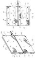
- the anode assembly 12 comprises a riser 14.
- the riser 14 has, on opposite sides, a first active anode surface 16 and a second active anode surface 18 (Figs. 1 and 3).
- the anode assembly 12 is supported, with respect to the riser, so that the active anode surfaces 16, 18 are movable away from each other, to expand the anode assembly, and towards each other, to contract the anode assembly.
- the anode assembly 12 of Figs. 1-3 is adapted to be positioned within an electrolytic cell between spaced-apart cathodes.
- the dimensions of the anode assembly 12, allow the anode assembly to be expanded, when positioned between cathode surfaces, a sufficient amount so that the active anode surfaces 16, 18 are essentially contiguous with the cathodes, establishing essentially a "minimum-gap".
- the first active anode surface 16 comprises a pair of anode sheets 20, 22, and the second active anode surface 18 comprises a pair of anode sheets 24, 26 (Figs. 1 and 3). All of the sheets 20, 22, 24 and 26 have a rectangular shape, and essentially the same width and height dimensions. For purposes of the present application, the width dimension of each anode sheet is essentially that dimension which extends parallel to the riser 14, and the height dimension is that dimension which extends perpendicular to the riser. All of the sheets 20, 22, 24 and 26 have a generally flat or planar profile. In the drawings of Figs.
- the sheets 20, 22, of the first active anode surface 16 lie in the same plane, and the anode sheets 24, 26, of the second active anode surface 18, lie in the same plane.
- the plane of sheets 24, 26 is parallel with the plane of sheets 20, 22.
- the anode sheets 20, 22 are spaced from each other by a gap 28, and the sheets 24, 26 are spaced from each by a gap 30 (Fig. 3).
- the anode assembly 12 is mounted in an electrolytic cell so that the riser 14 is fastened to a side wall of the cell at end 31, Figs. 1, 2.
- the anode sheets 22 and 26 extend widthwise across the cell adjacent the bottom of the cell, and define the bottom 32 of the anode assembly.
- the anode sheets 20 and 24 (Fig. 1) of the anode assembly extend widthwise across the cell adjacent the top of the cell, and define the top 34 of the anode assembly.
- the riser 14 can be mounted in the bottom of the cell and extend vertically in the cell.
- the anode sheets 20, 22, 24 and 26 can be formed from many different materials and have a variety of types of electrically conductive surfaces carried thereon.
- the sheets comprise a substrate of titanium which is expanded or perforated to form a mesh-like member, as shown in Figs. 1-3.
- approximately one-half of the total area of a sheet is open.
- the entire area of each sheet preferably is perforated or expanded uniformly.
- the coated anode sheets are inert in the electrolytic process with which they are used and frequently referred to as dimensionally stable.
- the anodes are not sacrificial or consumed in the process.
- the anodes usually comprise a substrate or base which is formed of a valve metal, such as titanium, tantalum, zirconium, aluminum, niobium and tungsten. These base metals are resistant to electrolytes and conditions used within electrolytic cells.
- a preferred valve metal is titanium. Titanium can be oxidized on its surface increasing the resistance of the valve metal to the passage of current. Therefore, it is customary to apply electrically conductive electro-catalytic coatings to the electrode substrate.
- the coatings have the capacity to continue to conduct current to the electrolyte over long periods of time without becoming passivated.
- Such coatings can contain catalytic metals or oxides from the platinum group metals such as platinum, palladium, iridium, ruthenium, rhodium and osmium.
- the coating also preferably contains a binding or protective agent such as oxides of titanium or tantalum, or other valve metals in sufficient amount to protect the platinum group metal or oxide from being removed from the electrode in the electrolysis process and to bind the platinum group metal or oxide to the electrode base.
- a binding or protective agent such as oxides of titanium or tantalum, or other valve metals in sufficient amount to protect the platinum group metal or oxide from being removed from the electrode in the electrolysis process and to bind the platinum group metal or oxide to the electrode base.
- An example of one such dimensionally stable anode is a titanium substrate which has been coated with an electrocatalytic coating containing ruthenium and titanium.
- the anode sheets 20, 22, 24 and 26 are supported in a manner which permits them to move such as by floating, between expanded and contracted conditions of the anode assembly 12.
- the anode assembly is shown in an expanded condition, so that the plane of sheets 20, 22 is spaced away from the riser 14, as is the plane of sheets 24, 26.
- the sheets 20, 22 In a contracted condition, the sheets 20, 22 would be pressed inwardly against the riser, as would sheets 24, 26.
- the assembly normal condition will be in an expanded state and that the assembly need be contracted only an amount which allows such assembly to be inserted into a space between a pair of cathodes of an electrolytic cell.
- the assembly normal condition can be in a contracted state and expanders can be used to expand the assembly after insertion in an electrolytic cell, in a manner known in the art.
- each anode sheet is supported by spring connectors to be described, which allow movement of one sheet of an anode surface without movement of the other sheet of such surface.
- the spring connectors hold each sheet so that its profile remains essentially flat in such movement, and so that each sheet lies in the same or an essentially parallel plane with other sheets of the anode assembly during such movement.
- each anode sheet 20, 22, 24, 26 is supported at two locations in the nature of a truss support for each sheet.
- a truss support is defined as an assemblage of members such as beams, which form a rigid framework.
- the spring connectors comprise a first pair of support connectors 40, 42 and a second pair of support connectors 44, 46.
- the first pair of support connectors 40, 42 are affixed to the riser 14 on opposite sides of the riser.
- the connectors 40, 42 are leaf connectors or a form of a leaf spring.
- the connectors 40, 42 are generally V-shaped and have a flat mid-portion 48 (Fig.
- each leaf arm 50, 52 has a flattened end 54, Fig. 3.
- the connectors 40, 42 are attached at flattened ends 54 to the inside of anode sheets 20, 22, 24 and 26.
- connector 42 is attached to anode sheets 20, 24 (see Fig. 3)
- connector 40 is attached to anode sheets 22, 26.
- the second pair of support connectors 44 and 46 are also leaf connectors or a form of a leaf spring. Referring to Fig. 3, the connectors 44, 46 are also V-shaped and preferably have the same configuration as connectors 40, 42. The second pair of support connectors 44, 46 are spaced outwardly away from riser 14. The second pair of connectors 44, 46 also have a flat mid-portion 48, a pair of leaf arms 50, 52, and flattened ends 54. In contrast to the first pair of connectors 40, 42, the second pair of support connectors 44, 46 are not fastened to anything at the mid-portion 48, but similar to connectors 40, 42, extend between oppositely positioned anode sheets. Thus, support connector 44 extends between and is connected to anode sheets 22, 26 and support connector 46 extends between and is connected to anode sheets 20, 24.
- each of the support connectors 40, 42, 44 and 46 extends the full width of each anode sheet to which it is attached.
- the attachment of the support connector flattened ends 54 to the anode sheets is by a plurality of aligned spaced-apart spot welds, achieved, for instance by resistance welding.
- the attachment of the mid-portions 48 of the first pair of connectors 40, 42 to the riser 14 is similarly by a plurality of aligned spaced-apart spot welds, achieved, for instance, by resistance welding.
- the criteria for the number of welds and spacing is primarily good electrical connection between the respective components, and mechanical strength of the connection between the respective components.
- the plurality of welds between the respective components lie in a plurality of straight weld lines which are parallel to each other and, in the embodiment of Figs. 1-3, to the axis of riser 14. It will be apparent from Fig. 3 that the spring connectors 40, 42, 44 and 46 are all deformable in essentially the same direction, namely in a direction which is at right angles to the axis of riser 14, and also at right angles to the planes of the multiple anode sheets 20, 22, 24 and 26.
- the connectors 40, 42, 44 and 46 are made of an expanded or perforate mesh, similar to the mesh of anode sheets 20, 22, 24 and 26. In contrast with the anode sheets, the connectors need not however be coated.
- the mesh construction of the connectors permits the connectors to be used in electrolytic cells adapted for the flow of electrolyte longitudinally through the cells. The electrolyte can flow past the connectors without being substantially impeded.
- An example of such a cell is one for the production of a chlorate.
- a preferred metal for the support connectors is a valve metal, such as titanium, which is dimensionally stable in an electrolytic cell.
- the specific shape of the connectors 40, 42, 44 and 46 can vary as long as the leaf arms 50, 52, are of sufficient length to provide connector flexibility.
- the connectors in a non-stressed condition, have leaf arms 50, 52 which form an angle of approximately 6° relative to a mid-plane bisecting each connector.
- the arms 50, 52 have a zigzag configuration which includes an intermediate leg 56 (Fig. 3).
- the flattened ends 54 extend outwardly making an angle of about 105° with respect to the intermediate legs 56.
- the arrangement of connectors 40, 42, 44 and 46, in the anode assembly of Figs. 1-3, is in the nature of a flexible truss support, as mentioned, similar to a bridge support.
- the connectors for each anode sheet, as in a bridge support maintain each sheet in a generally flat profile.
- the support for this sheet comprises leaf arm 50' (Fig. 3) of connector 42 and leaf arm 50'' of connector 46.
- Each leaf arm 50', 50'' extends the full width of the sheet 20 (parallel to riser 14), and is rigidly fastened to the sheet 20 at a plurality of weld points spaced-apart along a line parallel to riser 14.
- the leaf arms 50', 50'' are relatively stiff, in a width-wise direction, due to the bends in the zigzag configuration of the arms. This provides a relatively rigid support which resists deflection of the sheet 20, widthwise, from a generally flat profile. At the bottom, close to gap 28, Fig. 3, the sheet 20 is attached to the flattened end 54 of connector 42. Near the top 34 of the assembly, the sheet 20 is attached to the flattened end 54 of connector 46. Since the connectors 42, 46 have essentially the same configuration, and thus stiffness in leaf arms 50', 50'', the deflection or movement of the sheet 20 heightwise, from top to bottom, for whatever reason, will be about the same.
- the sheet 20 when the sheet 20 is caused to move, for instance due to contact of the anode assembly with an adjacent cathode, it maintains its generally flat profile, in essence floating in its contraction movement.
- the anode sheets of the anode assembly when allowed to expand from an initial contracted condition, established to permit insertion of the anode assembly in an electrolytic cell, the anode sheets of the anode assembly float outwardly, until the anode assembly is fully expanded, or until an anode sheet is prevented from further expansion by a cathode.
- the anode sheets maintain during movement not only a generally flat profile, but in addition, a planar orientation which is essentially parallel with the orientation of other anode sheets of the assembly.
- the anode assembly 12 of Figs. 1-3 also comprises an array of insulating spacer buttons 60 of a dielectric material, such as polyvinylidene fluoride (Kynar), polytetrafluoroethylene, and fluorinated ethylene propylene, which is resistant to conditions within the electrolytic cell.
- the insulating spacer buttons permit use of the anodes of the present invention in an electrolytic cell for the production of chlorates.
- Nafion membranes are generally positioned between the anodes and cathodes. These membranes insulate the anodes from the cathodes. The membranes are not required in an electrolytic cell for the production of a chlorate.
- each anode sheet 20-26 has an array of eight (8) spacer buttons 60.
- the spacer buttons are dimensioned to extend a sufficient distance from the outer surface of each anode sheet so that an adjacent cathode is contacted by at least one spacer button rather than a surface of an anode sheet. This maintains a small gap between each anode sheet and an adjacent cathode, sufficient to prevent shorting of an anode to a cathode.
- Each insulating spacer button 60 can be a single piece extending through a perforation of a sheet, having compressible enlarged ends which releasably engage the opposite sides of a sheet and hold the spacer buttons in position.
- the spacer buttons can be two piece members such as a rivet with enlarged heads engaging opposite sides of a sheet.
- the array of eight (8) spacer buttons is arranged across the face of a sheet strategically positioned so that contact with a cathode is prevented even though a cathode may be relatively badly warped.
- each sheet has along its edge, adjacent gaps 28, 30, an insulation channel 62, (Fig. 3).
- the insulation channels 62 provide additional protection against shorting with a cathode and in addition prevent an edge of one sheet from locking with an edge of an adjacent sheet during compression of an anode assembly.
- the channels 62 also function to stiffen the edges of the anode sheets 20-26 adjacent to the gaps 28, 30. Additional stiffening of the sheets is provided by lips 36 formed at the edges of the sheets adjacent the bottom 32 of the assembly and the top 34 of the assembly.
- each anode surface of an anode assembly into at least two individually movable sheets, and supporting each sheet so that it maintains a relatively flat profile, the individual sheets can be held in planes more parallel to the opposing surface of a cathode than is possible if a surface comprised only a single sheet. This in turn provides a more uniform anode to cathode gap and a more uniform current distribution across the face of an anode. Fewer hot spots are likely.
- the present invention allows each sheet to be positioned generally closer to an adjacent cathode without shorting than is possible if a sheet were more flexible.
- the V-shaped connectors 40, 42 are first welded to diametrically opposite sides of the anode riser 14. Preferably, they are joined to the riser 14 by a series of closely-spaced spot welds which provide both structural integrity and suitable electrical conductivity.
- the welding can be accomplished according to the process and with the apparatus disclosed in U.S. Patent No. 4,033,849. The disclosure of this patent is incorporated herein by reference. In essence, welding electrodes are reciprocated inwardly from opposite sides of the riser to form the necessary welds. Preferably, at least every other strand or ribbon of a titanium mesh connector is joined to the riser 14.
- the connectors can be held by jigs which maintain the connector surfaces parallel with the axis of the riser 14. Thereafter, the preformed anode sheets 20, 22, 24 and 26 are joined to the connectors 40, 42. Preferably this is also accomplished by a series of spot welds which electrically and structurally connect the connectors 40, 42 to the anode sheets.
- spot welds which electrically and structurally connect the connectors 40, 42 to the anode sheets.
- heavy copper conductor bars are temporarily positioned between the ends 54 of the connectors and welding electrodes are reciprocated against the anode sheets to complete the welding.
- a similar sequence of steps can be carried out with regard to welding the second pair of support connectors 44, 46 to the anode sheets.
- the anode assembly 12 of Figs. 1-3 contains four independently movable anode sheets, the assembly can comprise more than four sheets if desired.
- a sheet can further be segmented along its width, defining a separation gap from top to bottom about midway between opposite sides of the sheet.
- a sheet can be segmented from top to bottom by providing a gap about midway between the top and bottom of each sheet.
- the sheet furthermost removed from the assembly riser 14 can be connected to the riser by a support connector similar broadly in configuration to the support connectors 40, 42, but having leaf arms substantially longer than the leaf arms 50, 52 and positioned inside of the leaf arms 50, 52.
- the surfaces 16, 18 are segmented widthwise so that the gaps 28, 30 between adjacent sheets are parallel with riser 14.
- the surfaces could be segmented in a vertical direction so that the gaps between adjacent sheets are perpendicular to the riser 14.
- the anode assembly comprises a plurality of hairpin rods 70 which extend around the assembly.
- each hairpin rod 70 comprises a middle section 72 adjacent the assembly upper edge 34, legs 74 and 76 which depend from the middle section 72, and hook ends 78, 80, adjacent the assembly lower edge 32, at the ends of legs 74, 76.
- the hairpin rods are made of a flexible, plastic, dielectric material, such as polyvinylidene fluoride (Kynar), polytetrafluoroethylene, and fluorinated ethylene propylene, which is resistant to conditions within an electrolytic cell.
- each hairpin rod may have a diameter or width of about one-eighth inch.
- four hairpin rods 70 are spaced laterally around each anode assembly and are strategically positioned to prevent contact and shorting of the anode assembly with a cathode.
- Each hairpin rod, as shown in Fig. 4, is placed over the outside of the anode assembly with the middle section 72 against the top 34 of the assembly.
- the ends 78 and 80 are easily deformable and can be bent so that they extend upwardly into the spacing between the anode sheets at the bottom 32 of the assembly.
- the hairpin rods have sufficient flexibility that they allow floating movement of the anode sheets in the manner described above with respect to the embodiment of Figs. 1-3.
- the anode assembly can be compressed so that it can be installed within an electrolytic cell.
- the anode sheets can float outwardly, relatively independently, maintaining a substantially flat profile, to establish essentially, a uniform "minimum-gap" with an adjacent cathode.
Landscapes
- Chemical & Material Sciences (AREA)
- Engineering & Computer Science (AREA)
- Chemical Kinetics & Catalysis (AREA)
- Electrochemistry (AREA)
- Materials Engineering (AREA)
- Metallurgy (AREA)
- Organic Chemistry (AREA)
- Inorganic Chemistry (AREA)
- Electrolytic Production Of Metals (AREA)
- Electrolytic Production Of Non-Metals, Compounds, Apparatuses Therefor (AREA)
- Analysing Materials By The Use Of Radiation (AREA)
- Spinning Or Twisting Of Yarns (AREA)
Claims (24)
- Spreizbare Elektrodenbaugruppe für eine Elektrolysezelle, umfassend
einen Elektrodenheber,
erste und zweite aktive Elektrodenflächen, die einen Abstand voneinander haben und an entgegengesetzten Seiten des Elektrodenhebers vorgesehen sind, wobei jede Elektrodenfläche mehrere Elektrodenplatten umfaßt,
gleichartig konfigurierte Federverbindungsglieder,
die die Elektrodenplatten halten, wobei die Federverbindungsglieder eine Bewegung einer Platte einer Elektrodenfläche ermöglichen, ohne die anderen Platten der genannten Fläche zu bewegen, wobei jede Platte durch ein eine erste lineare Verbindung mit einer Elektrodenplatte herstellendes erstes Verbindungsglied und ein eine zweite lineare Verbindung mit der genannten Platte herstellendes zweites Verbindungsglied abgestützt ist, wobei die linearen Verbindungen voneinander und in bezug auf Ränder jeder Elektrodenplatte durch Distanzen voneinander beabstandet sind, die den Effekt haben, daß die genannte Platte unter Vorhandensein eines sich zwischen einer Elektrodenplatte auf einer Seite des Hebers und einer Elektrodenplatte auf der entgegengesetzten Seite des Hebers erstreckenden Verbindungsgliedes so gehalten ist, daß jedes Plattenprofil bei einer solchen Bewegung im wesentlichen eben bleibt, und wobei jede Platte in derselben oder in einer im wesentlichen parallelen Ebene mit anderen Platten der Elektrodenbaugruppe bei einer solchen Bewegung liegt. - Elektrodenbaugruppe nach Anspruch 1, wobei jede Elektrodenplatte durch zwei Federverbindungsglieder gehalten ist, wobei die Federverbindungsglieder in Form von Blattfedern ausgebildet und in im wesentlichen gleicher Richtung deformierbar sind.
- Elektrodenbaugruppe nach Anspruch 2, die eine zu dem Heber parallele Breitenabmessung hat, wobei sich das erste Verbindungsglied von dem Heber zu der Platte erstreckt und der Breitenabmessung der Platte zumindest im wesentlichen entsprechend ausgedehnt ist, wobei sich das zweite Verbindungsglied zwischen einer Platte der ersten Fläche auf einer Seite des Hebers und einer Platte der zweiten Fläche auf der entgegengesetzten Seite des Hebers erstreckt und wobei das zweite Verbindungsglied der Platte ebenfalls zumindest im wesentlichen entsprechend ausgedehnt ist.
- Elektrodenbaugruppe nach Anspruch 3, wobei jedes Verbindungsglied einen Zickzack-Querschnitt aufweist, der eine breitenweise Steifigkeit in bezug auf die genannte Platte bietet.
- Elektrodenbaugruppe nach Anspruch 4, wobei jede Elektrodenplatte eine Lippe längs einem unteren oder oberen Rand unter einem rechten Winkel zu der Ebene der Platte aufweist, um zusätzliche Steifigkeit in Richtung der Breite der Platte vorzusehen.
- Elektrodenbaugruppe nach Anspruch 5, wobei die Verbindungsglieder perforiert oder aus einem Streckmetallgitter hergestellt sind.
- Elektrodenbaugruppe nach Anspruch 6, wobei die Verbindungsglieder durch Widerstandsschweißung an einer Vielzahl von Punkten mit dem Heber und den Elektrodenplatten verschweißt sind.
- Elektrodenbaugruppe nach Anspruch 6, umfassend Isolationsmittel, die an den Elektrodenplatten angeordnet sind, um einen Kontakt einer Elektrodenplatte mit einer Kathode zu verhindern.
- Elektrodenbaugruppe nach Anspruch 8, wobei die Isolationsmittel eine Vielzahl von Abstandsknöpfen aus dielektrischem Material umfassen und wobei jede Elektrodenplatte ein Feld von Anstandsknöpfen trägt, die derart positioniert und dimensioniert sind, daß sie einen Zwischenraum zwischen der Platte und einer benachbarten Kathode aufrechterhalten.
- Elektrodenbaugruppe nach Anspruch 8, wobei die Isolationsmittel eine Vielzahl von länglichen Stäben aus dielektrischem Material umfassen, wobei die Stäbe eine Haarnadelkonfiguration haben, bei der Stabenden, welche gebogen sind und sich in den Zwischenraum zwischen einander gegenüberliegenden Platten der Baugruppe erstrecken, um die Elektrodenbaugruppe gewunden sind, wobei die Enden durch Perforationen der Elektrodenplatten vortreten und in das Gitter der Elektrodenplatten eingreifen.
- Elektrodenbaugruppe nach Anspruch 6, zur Verwendung als Anode, umfassend Anodenplatten aus einem beschichteten Metall, das in dem elektrolytischen Prozeß, in dem die Elektrodenbaugruppe verwendet wird, zumindest im wesentlichen resistent gegen Aufzehrung ist.
- Elektrodenbaugruppe nach Anspruch 1, wobei die Elektrodenplatten beschichtete Metallplatten sind, die in dem elektrolytischen Prozeß dimensionsstabil sind.
- Minimalspalt-Anodenbaugruppe für eine Elektrolysezelle, umfassend
einen länglichen Anodenheber,
Anodenflächen in allgemein parallelen Ebenen auf entgegengesetzten Seiten des Hebers, wobei jede Anodenfläche mehrere Anodenplatten umfaßt,
Federhaltemittel, die die Anodenplatten federnd halten, so daß eine Platte einer Anodenfläche eine Spielbewegung unabhängig von anderen Platten der genannten Anodenfläche ausführen kann, wobei die Federhaltemittel eine erste Federstütze, die die Form einer Blattfeder aufweist, welche eine erste lineare Verbindung mit einer Elektrodenplatte herstellt, und eine zweite Federstütze umfassen, die die Form einer Blattfeder aufweist, ähnlich der ersten Federstütze konfiguriert ist und eine zweite lineare Verbindung mit einer Elektrodenplatte herstellt, wobei die linearen Verbindungen voneinander und in bezug auf die Ränder der genannten Elektrodenplatte durch Distanzen beabstandet sind, welche den Effekt haben, daß die genannte Platte in einem ebenen Profil gehalten wird, wobei sich ein Verbinder zwischen einer Elektrodenplatte auf einer Seite des Hebers und einer Elektrodenplatte auf der entgegengesetzten Seite des Hebers erstreckt, und wobei zumindest eine der Stützen die Platte mit dem Heber elektrisch verbindet. - Baugruppe nach Anspruch 13, wobei die Federhaltemittel perforiert oder aus einem Streckmetallgitter hergestellt sind und wobei jede Platte eine Vielzahl von dielektrischen Abstandshaltern umfaßt, die dazu eingerichtet sind, einen Spalt zwischen einer Platte und einer benachbarten Kathode aufrechtzuerhalten.
- Baugruppe nach Anspruch 14, wobei die dielektrischen Abstandshalter eine Vielzahl von Abstandsknöpfen aus einem dielektrischen Material umfassen und wobei jede Anodenplatte ein Feld von Abstandsknöpfen trägt, die derart positioniert und dimensioniert sind, daß sie einen Spalt zwischen der genannten Platte und einer benachbarten Kathode aufrechterhalten.
- Baugruppe nach Anspruch 14, wobei die dielektrischen Abstandshalter eine Vielzahl von länglichen Stäben aus einem dielektrischen Material umfassen, wobei die Stäbe eine Haarnadelkonfiguration haben, bei der Stabenden, welche gebogen sind und sich in den Zwischenraum zwischen einander gegenüberliegenden Platten der Flächen erstrecken, um die Anodenflächen gewunden sind, und wobei die Enden durch Perforationen der Anodenplatten vorstehen und in das Gitter der Anodenplatten eingreifen.
- Baugruppe nach Anspruch 13, wobei jede Anodenfläche zwei Anodenplatten umfaßt, die normalerweise koplanar sind.
- Verwendung einer Baugruppe nach irgendeinem der Ansprüche 13 bis 17 in einer Chlorat erzeugenden Elektrolysezelle.
- Membranfreie Elektrolysezelle, umfassend
eine Vielzahl von Kathoden und
eine Vielzahl von Anodenbaugruppen in abwechselnder Folge mit den Kathoden, wobei die Verbesserung jeder Anodenbaugruppe folgende Merkmale umfaßt:(I) einen länglichen Anodenheber,(II) voneinander beabstandete Anodenflächen in allgemein parallelen Ebenen auf entgegengesetzten Seiten des Hebers,(III) wobei jede Anodenfläche mehrere Anodenplatten umfaßt,(IV) Federhaltemittel, die die Anodenplatten federnd halten, so daß eine Platte einer Anodenfläche eine Spielbewegung unabhängig von anderen Platten der genannten Anodenfläche ausführen kann, wobei die Federhaltemittel eine erste Federstütze, die die Form einer Blattfeder hat, welche eine erste lineare Verbindung mit einer Elektrodenplatte herstellt, und eine zweite Federstütze umfassen, die ähnlich der ersten Federstütze konfiguriert ist, die Form einer Blattfeder aufweist und eine zweite lineare Verbindung mit einer Elektrodenplatte herstellt, wobei die linearen Verbindungen voneinander und von den Rändern der genannten Elektrodenplatte durch Distanzen beabstandet sind, welche den Effekt haben, daß die genannte Platte in einem ebenen Profil gehalten wird, wobei sich ein Verbinder zwischen einer Elektrodenplatte auf einer Seite des Hebers und einer Elektrodenplatte auf der entgegengesetzten Seite des Hebers erstreckt und wobei zumindest eine der Stützen die genannte Platte mit dem Heber elektrisch verbindet. - Zelle nach Anspruch 19, wobei jede Platte eine Vielzahl von dielektrischen Abstandshaltern umfaßt, die dazu eingerichtet sind, einen Spalt zwischen einer Platte und einer benachbarten Kathode aufrechtzuerhalten.
- Zelle nach Anspruch 20, wobei die dielektrischen Abstandshalter eine Vielzahl von Abstandsknöpfen aus einem dielektrischen Material umfassen und wobei jede Anodenplatte ein Feld von Abstandsknöpfen trägt, die derart positioniert und dimensioniert sind, daß sie einen Spalt zwischen der Platte und einer benachbarten Kathode aufrechterhalten.
- Zelle nach Anspruch 20, wobei die dielektrischen Abstandshalter eine Vielzahl von länglichen Stäben aus einem dielektrischen Material umfassen, wobei die Stäbe eine Haarnadelkonfiguration haben, bei der sich Stabenden, welche gebogen sind und sich in den Zwischenraum zwischen einander gegenüberliegenden Platten der Baugruppe erstrecken, um die Anodenbaugruppe gewunden sind, und wobei die Enden durch Perforationen der Anodenplatten vorstehen und in das Gitter der Anodenplatten eingreifen.
- Zelle nach Anspruch 19, wobei jede Anodenfläche zwei Anodenplatten umfaßt, die normalerweise koplanar sind.
- Verwendung einer Zelle nach irgendeinem der Ansprüche 19 bis 23 zur Erzeugung eines Chlorats.
Applications Claiming Priority (2)
| Application Number | Priority Date | Filing Date | Title |
|---|---|---|---|
| US07/557,348 US5100525A (en) | 1990-07-25 | 1990-07-25 | Spring supported anode |
| US557348 | 1995-11-14 |
Publications (2)
| Publication Number | Publication Date |
|---|---|
| EP0468285A1 EP0468285A1 (de) | 1992-01-29 |
| EP0468285B1 true EP0468285B1 (de) | 1995-02-01 |
Family
ID=24225039
Family Applications (1)
| Application Number | Title | Priority Date | Filing Date |
|---|---|---|---|
| EP91111510A Expired - Lifetime EP0468285B1 (de) | 1990-07-25 | 1991-07-10 | Mit Federn unterstützte Anode |
Country Status (5)
| Country | Link |
|---|---|
| US (1) | US5100525A (de) |
| EP (1) | EP0468285B1 (de) |
| AT (1) | ATE118046T1 (de) |
| CA (1) | CA2044058C (de) |
| DE (1) | DE69107135D1 (de) |
Families Citing this family (14)
| Publication number | Priority date | Publication date | Assignee | Title |
|---|---|---|---|---|
| IT1263900B (it) | 1993-02-12 | 1996-09-05 | Permelec Spa Nora | Migliorata cella di elettrolisi cloro-soda a diaframma poroso e processo relativo |
| US5445723A (en) * | 1994-05-31 | 1995-08-29 | Hoefer Scientific Instruments | Blotting apparatus |
| JP3608880B2 (ja) * | 1996-08-07 | 2005-01-12 | クロリンエンジニアズ株式会社 | 活性陰極の再活性化方法および再活性化した陰極を備えたイオン交換膜電解槽 |
| IT1291525B1 (it) * | 1997-04-10 | 1999-01-11 | De Nora Spa | Anodo per cella elettrochimica a diaframma |
| SE9800698D0 (sv) * | 1998-03-05 | 1998-03-05 | Permascand Ab | Device for electrochemical cell |
| RU2198843C1 (ru) * | 2001-10-25 | 2003-02-20 | Государственный научный центр - Научно-исследовательский институт атомных реакторов | Способ хроматографического извлечения стронция из растворов |
| ITMI20031269A1 (it) * | 2003-06-24 | 2004-12-25 | De Nora Elettrodi Spa | Nuovo anodo espandibile per celle a diaframma. |
| DE102005057910A1 (de) * | 2005-12-02 | 2007-06-06 | Rössle & Wanner GmbH | Matratze |
| US20100032221A1 (en) * | 2008-08-07 | 2010-02-11 | Charles Robert Storey | Electrolysis system for hydrogen and oxygen production |
| TWI655324B (zh) * | 2014-02-19 | 2019-04-01 | 義大利商第諾拉工業公司 | 電解槽之陽極結構以及金屬電解場中金屬澱積方法和系統 |
| IT201600083106A1 (it) * | 2016-08-05 | 2018-02-05 | Industrie De Nora Spa | Struttura di elettrodo provvista di resistori |
| ITUA20161470A1 (it) * | 2016-03-09 | 2017-09-09 | Industrie De Nora Spa | Struttura di elettrodo provvista di resistori |
| US11136684B2 (en) * | 2016-03-09 | 2021-10-05 | Industrie De Nora S.P.A. | Electrode structure provided with resistors |
| US11390956B1 (en) * | 2021-06-01 | 2022-07-19 | Verdagy, Inc. | Anode and/or cathode pan assemblies in an electrochemical cell, and methods to use and manufacture thereof |
Family Cites Families (11)
| Publication number | Priority date | Publication date | Assignee | Title |
|---|---|---|---|---|
| DE563393C (de) * | 1929-02-05 | 1932-11-04 | I G Farbenindustrie Akt Ges | Elektrolytische Zelle |
| US3674676A (en) * | 1970-02-26 | 1972-07-04 | Diamond Shamrock Corp | Expandable electrodes |
| US4033849A (en) * | 1975-05-09 | 1977-07-05 | Diamond Shamrock Corporation | Electrode and apparatus for forming the same |
| US4028214A (en) * | 1976-01-28 | 1977-06-07 | Olin Corporation | Adjustable electrode |
| US4120773A (en) * | 1977-08-25 | 1978-10-17 | Hooker Chemicals & Plastics Corp. | Compressible self guiding electrode assembly |
| US4096054A (en) * | 1977-10-26 | 1978-06-20 | Olin Corporation | Riserless flexible electrode assembly |
| US4154667A (en) * | 1978-01-03 | 1979-05-15 | Diamond Shamrock Corporation | Method of converting box anodes to expandable anodes |
| US4231143A (en) * | 1978-10-16 | 1980-11-04 | Diamond Shamrock Corporation | Electrode and apparatus for forming the same |
| FR2513663B1 (fr) * | 1981-09-30 | 1986-02-28 | Creusot Loire | Electrolyseur du type filtre-presse |
| DE3223701A1 (de) * | 1982-06-25 | 1983-12-29 | Metallgesellschaft Ag, 6000 Frankfurt | Membran-elektrolysezelle mit vertikal angeordneten elektroden |
| JPS59182980A (ja) * | 1983-04-01 | 1984-10-17 | Chlorine Eng Corp Ltd | フイルタ−プレス型イオン交換膜法電解槽 |
-
1990
- 1990-07-25 US US07/557,348 patent/US5100525A/en not_active Expired - Lifetime
-
1991
- 1991-06-06 CA CA002044058A patent/CA2044058C/en not_active Expired - Fee Related
- 1991-07-10 AT AT91111510T patent/ATE118046T1/de not_active IP Right Cessation
- 1991-07-10 DE DE69107135T patent/DE69107135D1/de not_active Expired - Lifetime
- 1991-07-10 EP EP91111510A patent/EP0468285B1/de not_active Expired - Lifetime
Also Published As
| Publication number | Publication date |
|---|---|
| DE69107135D1 (de) | 1995-03-16 |
| US5100525A (en) | 1992-03-31 |
| CA2044058A1 (en) | 1992-01-26 |
| CA2044058C (en) | 1998-01-20 |
| EP0468285A1 (de) | 1992-01-29 |
| ATE118046T1 (de) | 1995-02-15 |
Similar Documents
| Publication | Publication Date | Title |
|---|---|---|
| EP0468285B1 (de) | Mit Federn unterstützte Anode | |
| EP0080288B1 (de) | Elektrodenstruktur zur Verwendung in einer elektrolytischen Zelle vom Filterpressentyp | |
| JP3707985B2 (ja) | アルカリ金属塩電解槽 | |
| JP7167191B2 (ja) | 弾性支持要素を有する電解セル | |
| CA1189022A (en) | Electrode with support member and elongated members parallel thereto | |
| US3941676A (en) | Adjustable electrode | |
| EP0690148B1 (de) | Reparatur von maschenförmigen Elektroden die im Abstand von einem Elektrodenboden liegen | |
| EP0132079B1 (de) | Verfahren zum Zusammenbau einer Elektrolysezelle der Filterpressenbauart | |
| CA1074730A (en) | Electrolytic diaphragm cells | |
| EP0019360B1 (de) | Spreizbare Elektrode für eine Diaphragma- oder Membran-Elektrolysezelle sowie besagte Elektrolysezelle | |
| EP0112902B1 (de) | Elektrode in doppelter l-form für salzwasserelektrolysezelle | |
| US4855032A (en) | Electrode structure | |
| US4096054A (en) | Riserless flexible electrode assembly | |
| US4026785A (en) | Adjustable electrode | |
| US4028214A (en) | Adjustable electrode | |
| EP0568071A1 (de) | Elektrolysezelle | |
| US5225061A (en) | Bipolar electrode module | |
| US4482448A (en) | Electrode structure for electrolyser cells | |
| CA1128002A (en) | Anode with current feeder and resilient electrode sheets attached to it | |
| US3975255A (en) | Inter-electrode spacing in diaphragm cells | |
| EP0266106B1 (de) | Verfahren zur Zusammensetzung einer filterpressenartigen Struktur | |
| US5340457A (en) | Electrolytic cell | |
| EP0082643B1 (de) | Elektrodenaufbau für Elektrolysezellen | |
| US4056459A (en) | Anode assembly for an electrolytic cell | |
| CA1127596A (en) | Riserless flexible electrode assembly |
Legal Events
| Date | Code | Title | Description |
|---|---|---|---|
| PUAI | Public reference made under article 153(3) epc to a published international application that has entered the european phase |
Free format text: ORIGINAL CODE: 0009012 |
|
| AK | Designated contracting states |
Kind code of ref document: A1 Designated state(s): AT BE CH DE DK ES FR GB GR IT LI LU NL SE |
|
| 17P | Request for examination filed |
Effective date: 19920514 |
|
| 17Q | First examination report despatched |
Effective date: 19930512 |
|
| GRAA | (expected) grant |
Free format text: ORIGINAL CODE: 0009210 |
|
| ITF | It: translation for a ep patent filed | ||
| AK | Designated contracting states |
Kind code of ref document: B1 Designated state(s): AT BE CH DE DK ES FR GB GR IT LI LU NL SE |
|
| PG25 | Lapsed in a contracting state [announced via postgrant information from national office to epo] |
Ref country code: NL Effective date: 19950201 Ref country code: LI Effective date: 19950201 Ref country code: GR Free format text: LAPSE BECAUSE OF FAILURE TO SUBMIT A TRANSLATION OF THE DESCRIPTION OR TO PAY THE FEE WITHIN THE PRESCRIBED TIME-LIMIT Effective date: 19950201 Ref country code: ES Free format text: THE PATENT HAS BEEN ANNULLED BY A DECISION OF A NATIONAL AUTHORITY Effective date: 19950201 Ref country code: DK Effective date: 19950201 Ref country code: CH Effective date: 19950201 Ref country code: BE Effective date: 19950201 Ref country code: AT Effective date: 19950201 |
|
| REF | Corresponds to: |
Ref document number: 118046 Country of ref document: AT Date of ref document: 19950215 Kind code of ref document: T |
|
| REF | Corresponds to: |
Ref document number: 69107135 Country of ref document: DE Date of ref document: 19950316 |
|
| ET | Fr: translation filed | ||
| PG25 | Lapsed in a contracting state [announced via postgrant information from national office to epo] |
Ref country code: SE Effective date: 19950501 |
|
| PG25 | Lapsed in a contracting state [announced via postgrant information from national office to epo] |
Ref country code: DE Effective date: 19950503 |
|
| REG | Reference to a national code |
Ref country code: CH Ref legal event code: PL |
|
| PG25 | Lapsed in a contracting state [announced via postgrant information from national office to epo] |
Ref country code: GB Effective date: 19950710 |
|
| NLV1 | Nl: lapsed or annulled due to failure to fulfill the requirements of art. 29p and 29m of the patents act | ||
| PG25 | Lapsed in a contracting state [announced via postgrant information from national office to epo] |
Ref country code: LU Free format text: LAPSE BECAUSE OF NON-PAYMENT OF DUE FEES Effective date: 19950731 |
|
| PLBE | No opposition filed within time limit |
Free format text: ORIGINAL CODE: 0009261 |
|
| STAA | Information on the status of an ep patent application or granted ep patent |
Free format text: STATUS: NO OPPOSITION FILED WITHIN TIME LIMIT |
|
| 26N | No opposition filed | ||
| GBPC | Gb: european patent ceased through non-payment of renewal fee |
Effective date: 19950710 |
|
| PGFP | Annual fee paid to national office [announced via postgrant information from national office to epo] |
Ref country code: FR Payment date: 20040702 Year of fee payment: 14 |
|
| PG25 | Lapsed in a contracting state [announced via postgrant information from national office to epo] |
Ref country code: IT Free format text: LAPSE BECAUSE OF NON-PAYMENT OF DUE FEES Effective date: 20050710 |
|
| PG25 | Lapsed in a contracting state [announced via postgrant information from national office to epo] |
Ref country code: FR Free format text: LAPSE BECAUSE OF NON-PAYMENT OF DUE FEES Effective date: 20060331 |
|
| REG | Reference to a national code |
Ref country code: FR Ref legal event code: ST Effective date: 20060331 |