EP0468316A2 - Zufuhrsystem für einen Sensor - Google Patents
Zufuhrsystem für einen Sensor Download PDFInfo
- Publication number
- EP0468316A2 EP0468316A2 EP91111658A EP91111658A EP0468316A2 EP 0468316 A2 EP0468316 A2 EP 0468316A2 EP 91111658 A EP91111658 A EP 91111658A EP 91111658 A EP91111658 A EP 91111658A EP 0468316 A2 EP0468316 A2 EP 0468316A2
- Authority
- EP
- European Patent Office
- Prior art keywords
- catheter
- signal line
- sensor
- line
- tubular housing
- Prior art date
- Legal status (The legal status is an assumption and is not a legal conclusion. Google has not performed a legal analysis and makes no representation as to the accuracy of the status listed.)
- Withdrawn
Links
- 239000000523 sample Substances 0.000 claims abstract description 19
- 238000011109 contamination Methods 0.000 claims abstract description 10
- 239000012530 fluid Substances 0.000 claims description 29
- 238000004891 communication Methods 0.000 claims description 7
- 230000000813 microbial effect Effects 0.000 claims description 5
- 239000012528 membrane Substances 0.000 claims description 3
- 230000004888 barrier function Effects 0.000 claims description 2
- 230000013011 mating Effects 0.000 claims description 2
- 238000007789 sealing Methods 0.000 claims 1
- 239000007789 gas Substances 0.000 description 7
- 239000008280 blood Substances 0.000 description 4
- 210000004369 blood Anatomy 0.000 description 4
- 238000012544 monitoring process Methods 0.000 description 4
- IAYPIBMASNFSPL-UHFFFAOYSA-N Ethylene oxide Chemical compound C1CO1 IAYPIBMASNFSPL-UHFFFAOYSA-N 0.000 description 3
- 125000006850 spacer group Chemical group 0.000 description 3
- 230000000721 bacterilogical effect Effects 0.000 description 2
- 230000036772 blood pressure Effects 0.000 description 2
- 230000006835 compression Effects 0.000 description 2
- 238000007906 compression Methods 0.000 description 2
- 238000001727 in vivo Methods 0.000 description 2
- 238000002347 injection Methods 0.000 description 2
- 239000007924 injection Substances 0.000 description 2
- 239000004033 plastic Substances 0.000 description 2
- 239000011148 porous material Substances 0.000 description 2
- 230000002792 vascular Effects 0.000 description 2
- 241000894006 Bacteria Species 0.000 description 1
- HTTJABKRGRZYRN-UHFFFAOYSA-N Heparin Chemical compound OC1C(NC(=O)C)C(O)OC(COS(O)(=O)=O)C1OC1C(OS(O)(=O)=O)C(O)C(OC2C(C(OS(O)(=O)=O)C(OC3C(C(O)C(O)C(O3)C(O)=O)OS(O)(=O)=O)C(CO)O2)NS(O)(=O)=O)C(C(O)=O)O1 HTTJABKRGRZYRN-UHFFFAOYSA-N 0.000 description 1
- 229910000831 Steel Inorganic materials 0.000 description 1
- 230000001154 acute effect Effects 0.000 description 1
- 238000007792 addition Methods 0.000 description 1
- 239000003146 anticoagulant agent Substances 0.000 description 1
- 229940127219 anticoagulant drug Drugs 0.000 description 1
- 210000001367 artery Anatomy 0.000 description 1
- 210000001124 body fluid Anatomy 0.000 description 1
- 239000004020 conductor Substances 0.000 description 1
- 238000011161 development Methods 0.000 description 1
- 238000006073 displacement reaction Methods 0.000 description 1
- 239000013536 elastomeric material Substances 0.000 description 1
- 230000002708 enhancing effect Effects 0.000 description 1
- 239000000835 fiber Substances 0.000 description 1
- 229960002897 heparin Drugs 0.000 description 1
- 229920000669 heparin Polymers 0.000 description 1
- 230000000670 limiting effect Effects 0.000 description 1
- 238000000034 method Methods 0.000 description 1
- 238000012986 modification Methods 0.000 description 1
- 230000004048 modification Effects 0.000 description 1
- 239000002991 molded plastic Substances 0.000 description 1
- 210000003739 neck Anatomy 0.000 description 1
- 239000013307 optical fiber Substances 0.000 description 1
- 230000036316 preload Effects 0.000 description 1
- 230000001681 protective effect Effects 0.000 description 1
- 238000005070 sampling Methods 0.000 description 1
- 239000000243 solution Substances 0.000 description 1
- 239000010959 steel Substances 0.000 description 1
- 230000001954 sterilising effect Effects 0.000 description 1
- 210000003462 vein Anatomy 0.000 description 1
Images


Classifications
-
- A—HUMAN NECESSITIES
- A61—MEDICAL OR VETERINARY SCIENCE; HYGIENE
- A61M—DEVICES FOR INTRODUCING MEDIA INTO, OR ONTO, THE BODY; DEVICES FOR TRANSDUCING BODY MEDIA OR FOR TAKING MEDIA FROM THE BODY; DEVICES FOR PRODUCING OR ENDING SLEEP OR STUPOR
- A61M25/00—Catheters; Hollow probes
- A61M25/01—Introducing, guiding, advancing, emplacing or holding catheters
- A61M25/0105—Steering means as part of the catheter or advancing means; Markers for positioning
- A61M25/0111—Aseptic insertion devices
Definitions
- This invention generally pertains to a device used for advancing a probe into an attached tube, and more specifically, to a device for delivering a medical sensor through an intravascular catheter.
- the sensor delivery device must also satisfy other requirements. Prior to use of the delivery device, the sensor must be sterile and it must be maintained free from outside bacteriological contamination. The sensor may be stored in the delivery device prior to use, or withdrawn from the catheter into the delivery device during its use. A contaminant-free environment inside the portion of the delivery device to which the sensor is exposed should thus be maintained as the sensor is advanced through the catheter, to permit withdrawal of the sensor for subsequent reuse with the same patient. Bodily fluid leakage from the catheter through the delivery device must be avoided; yet, the delivery device should permit sampling of blood pressure, withdrawal of blood samples, and introduction of medicinal fluids into the circulatory system of the patient.
- the delivery device should control the position of the sensor relative to the distal end of the catheter to ensure that the sensor is properly exposed to a patient's bloodstream but does not extend so far beyond the end of the catheter that it is no longer protected by an anticoagulant heparin solution flowing through the catheter.
- fiber-optic blood gas sensors used to monitor PC0 2 and P0 2 are designed to extend into the bloodstream only a few hundredths of an inch beyond a distal end of the catheter. Thus, it is critically important that the delivery device properly position the sensor with respect to the distal end of the catheter.
- an apparatus for maintaining a medical device in a sterile environment and delivering the sensor and an attached signal line through a catheter.
- the apparatus includes an elongate tubular housing having a proximal end and a distal end, the distal end being adapted for attachment to the catheter.
- the medical device is disposed within a sterile environment comprising an interior of the tubular housing, and is movable from that position through the catheter, after the catheter is attached to the tubular housing.
- a flexible sheath disposed within the interior of the tubular housing sealingly extends between the tubular housing and the signal line.
- the flexible sheath sealingly encloses the sensor within the sterile environment, and as the medical device is advanced from the interior of the tubular housing into the catheter, the flexible sheath collapses so that the sterile environment is maintained.
- the flexible sheath everts (i.e., turns inside-out). The flexible sheath prevents outside contamination of the sterile environment that might otherwise result due to exposure of the interior to a nonsterile portion of the signal line as the line is advanced into the tubular housing.
- a sliding seal is disposed between the distal and proximal ends of the tubular housing, in close sliding contact with the line.
- the sliding seal prevents fluid from flowing around the line from the distal end of the housing into the proximal end, but permits the line to slide longitudinally through the sliding seal.
- a passage in fluid communication with the interior of the tubular housing is provided for infusing and withdrawing fluid.
- the fluid freely flows through the catheter, around and past the medical device and its attached signal line.
- the passage is disposed within a sidewall of the tubular housing, between the distal end of the tubular housing and the sliding seal.
- the apparatus includes a sterilant inlet opening into the interior of the tubular housing to provide fluid communication with the interior.
- the sterilant inlet opening enables a sterilant gas to be infused into the interior and is covered with a microbial filter through which air passes freely as the medical device is advanced and withdrawn through the catheter.
- a stop disposed on the line at a predefined distance from the medical device.
- the stop abuts against an inner surface of a fitting on the catheter to limit advancement of the medical device so that it extends only a predefined distance beyond a distal end of the catheter.
- At least one passage is formed in the stop to permit fluid to flow past the stop when it is abutting the inner surface of the catheter fitting.
- Means are also provided for preventing rotation of the signal line relative to the tubular housing, thereby preventing twisting of the flexible sheath that might otherwise occur.
- the means for preventing rotation comprise a ridge and a mating groove that extend between an inner surface of the tubular housing and an outer surface of the signal line, generally in alignment with its longitudinal axis. The ridge engages the groove to prevent rotation of the signal line, yet allows longitudinal movement of the signal line relative to the tubular housing.
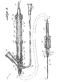
- Sensor delivery device 10 can be used for storing a sensor 12 in a sterile environment and for controlling the position of the sensor in respect to a distal end of a catheter 14.
- sensor delivery device 10 Prior to use of sensor 12, sensor delivery device 10 is connected to catheter 14, which may be preinserted within a patient's artery or vein (not shown).
- Sensor 12 may, for example, comprise a fiber optic probe for monitoring blood gases in vivo.
- Sensor delivery device 10 is adapted to connect to catheter 14 by provision of an internally threaded connector 18, which is disposed on a distal end of an elongate flexible tube 20.
- a proximal end of catheter 14 includes an externally threaded, generally cylindrical, nozzle-shaped hub or fitting 17, which engages connector 18.
- sensor 12 is advanced through catheter 14 from a sterile environment within elongate tube 20, until the sensor extends into the patient's bloodstream, controllably positioned by the delivery device to a point that is a few hundredths of an inch beyond the distal end of catheter 14.
- An important aspect of the present invention is its ability to precisely position sensor 12 with respect to the distal end of catheter 14.
- Elongate tube 20 is attached to a rigid housing 22.
- a signal line 16 attached to sensor 12 extends along a longitudinal axis of both elongate tube 20 and rigid housing 22, through a cap 24.
- Cap 24 is rotatably attached to the signal line at a predetermined proximal distance above sensor 12; the cap is secured to a proximal end of rigid housing 22 when sensor 12 is advanced from its storage position through catheter 14, to its position of use.
- Signals (light and/or electrical) produced by sensor 12 are conveyed through signal line 16 to and from appropriate connected instrumentation (not shown).
- Signal line 16 comprises a plurality of optical fibers and electrical conductors (not separately shown) that are enclosed within a protective plastic sleeve 15.
- tube 15A covers the distal end of signal line 16, except where sensor 12 is exposed.
- Tube 15A is separate from but joined to plastic sleeve 15 and protects and stiffens the portion of signal line 16 that moves within catheter 14. Tube 15A is shown more clearly in FIGURES 7, 8, and 8A.
- the diameter of sleeve 15 is less than the internal diameter of elongate tube 20.
- the diameter of tube 15A is less than the internal diameter of catheter 14. Therefore, the space surrounding sleeve 15 and tube 15A, i.e., the annular space between sleeve 15 and the inner surfaces of elongate tube 20 and the annular space between tube 15A and catheter 14, provides a path for fluid communication with the patient's bloodstream for monitoring blood pressure, withdrawal of blood samples, or injection of medicinal fluids while sensor 12 is in use.
- Fluids are either withdrawn from or injected into the bloodstream through a fluid access tube 26, which extends laterally through a sidewall of elongate tube 20, from a portion of rigid housing 22 that is attached to the elongate tube.
- Fluid access tube 26 includes a connector 28 on its distal end, for connection to appropriate monitoring equipment and/or fluid injection/withdrawal apparatus (none shown).
- the preferred embodiment also includes a sterilant inlet 30 that extends at an acute angle outwardly from rigid housing 22, adjacent the point where it connects to elongate tube 20.
- a microporous filter screen 32 having a maximum pore size of approximately 0.2 microns is fitted into the open end of sterilant inlet 30. Due to the small pore size, microporous filter screen 32 functions as a microbial filter and excludes bacteriological contamination from entering rigid housing 22 when air is drawn into or expelled from the rigid housing as the sensor is moved.
- an eversible sheath 34 extends between a bonded joint 38 and signal line 16. Bonded joint 38 circumferentially surrounds rigid housing 22 at about its midpoint.
- the end of the eversible sheath attached to sleeve 15 includes a compression ring 36 that is elastically biased to seal around an annular fitting 46 bonded to sleeve 15.
- Eversible sheath 34 preferably comprises an elastomeric membrane, formed of rubber or other suitable elastomeric material.
- the eversible sheath functions as a contamination barrier, protecting the sterile environment within elongate tube 20 (in which the sensor is stored prior to use) from contamination by exposure to externally introduced bacteria as sensor 12 is advanced through catheter 14 from its retracted position into its position of use. Further, if it becomes necessary to withdraw sensor 12 back through catheter 14 into its retracted position, contamination of the sensor due to exposure of an interior part of rigid housing 22 to nonsterile portions of signal line 16 is thus prevented.
- a non-eversible sheath (not shown) that simply collapses as sensor 12 is either advanced or withdrawn from catheter 14 might alternatively be used in place of eversible sheath 34. However, the non-eversible sheath would not permit the extent of travel of sensor 12 provided by eversible sheath 34 and would be more prone to damage or perforation during repeated use of the sensor delivery device.
- FIGURES 2 and 3 the disposition of sensor 12 and eversible sheath 34 are illustrated respectively prior to and after advancement of the sensor through catheter 14.
- sensor 12 is shown in its retracted position, i.e., disposed within the distal end of elongate tube 20.
- eversible sheath 34 Prior to advancement of sensor 12, eversible sheath 34 extends from bonded joint 38 toward the proximal end of rigid housing 22.
- a ring 44 formed at one end of eversible sheath 34 around its circumference, is captured between an upper portion 40 and a lower portion 42 of rigid housing 22, where they are connected at bonded joint 38.
- Compression ring 36 at the opposite end of eversible sheath 34 is bonded to annular fitting 46.
- sensor delivery device 10 Prior to being packaged for shipment to an end user, sensor delivery device 10 is subjected to a sterilizing procedure which may include exposure to ethylene oxide gas.
- the ethylene oxide gas is drawn into the interior of rigid housing 22, through microporous filter screen 32, which covers the outer end of sterilant inlet 30.
- the gas produces a sterile environment 48 around the portion of signal line 16 that extends into elongate tube 20 of sensor delivery device 10.
- Ethylene oxide gas is also drawn into the interior of elongate tube 20 through both connector 18 and fluid access tube 26.
- Alternative means may be used to sterilize the interior of rigid housing 22 and elongate tube 20.
- O-ring sliding seal 52 is disposed between the end of rigid housing 22 that connects to elongate tube 20 and fluid access tube 26.
- O-ring sliding seal 52 is sized so that its inner diameter is slightly smaller than the diameter of sleeve 15, thereby preventing fluid flowing from elongate tube 20 into the interior of rigid housing 22.
- sleeve 15 slides easily through O-ring sliding seal 52 as sensor 12 and signal line 16 are advanced through catheter 14.
- signal line 16 has been advanced into the interior of rigid housing 22 sufficiently so that threads 60, which are formed on an interior surface of cap 24, can engage a matching threaded ridge 62 that is formed on the outer surface of rigid housing 22, adjacent its proximal end.
- the signal line moves the attached sensor forward through catheter 14, until a probe stop 54 on sleeve 15 prevents further movement of the sensor, as explained below.
- sensor 12 is exposed a predefined distance at the distal end of catheter 14.
- Advancement of signal line 16 in this fashion also causes eversible sheath 34 to turn inside out. Eversible sheath 34 prevents contamination of the interior of rigid housing 22 distal of bonded joint 38 that would otherwise occur, due to exposure of the interior to a nonsterile portion 50 of signal line 16.
- microporous filter screen 32 allows air to flow freely in and out of the interior of rigid housing 22, due to displacement by eversible sheath 34, thereby preventing O-ring sliding seal 52 and the eversible sheath from being subjected to any significant differential pressure in respect to atmospheric pressure.
- probe stop 54 is bonded to sleeve 15 on signal line 16 at a predefined precise distance proximally behind the sensor.
- the placement of probe stop 54 at a proper position on signal line 16 is critical in this application and should be accomplished within a tolerance of ⁇ 0.005 inches, with the aid of a microscope. In other applications of the invention, the tolerance for positioning the probe stop may be different.
- Probe stop 54 which is shown in greater detail in FIGURES 7 and 8, is slid along tube 15A and sleeve 15 to the predetermined position, which can vary as a function of the length of catheter 14, before being bonded in place, and is thus adapted to adjust the position of sensor 12 with respect to the distal end of catheters of different length when the sensor is fully advanced through the catheter. Alternatively, the disposition of sensor 12 can be controlled in respect to the position of the probe stop.
- a shoulder 56 on the forward or distal end of probe stop 54 contacts an abutting surface 58 formed at a point where the internal diameter of a generally cylindrical fitting 17 on catheter 14 necks down.
- Shoulder 56 is tapered to a conical shape that matches the shape of abutting surface 58 and includes a plurality of longitudinal grooves 59 that enable fluid flow past the shoulder when it is seated against the abutting surface.
- probe stop 54 on signal line 16 controls the distance that sensor 12 extends beyond the distal end of catheter 14 to a predefined range (about ⁇ 0.02" in the preferred embodiment).
- cap 24 is positioned on signal line 16 at a slightly greater distance behind probe stop 54 than the distance between abutting shoulder 56 and the proximal end of rigid housing 22 so that an excessive length of signal line 16 is advanced into the rigid housing when the cap is secured thereto.
- the stiffness of sleeve 15 preloads probe stop 54 against abutting surface 58 at all times, even when elongate tube 20 is bent into a curve, due to the added length of signal line 16 that is forced into the rigid housing distal of the cap.
- FIGURE 4 a second preferred embodiment of the sensor delivery device is illustrated generally at reference numeral 10'.
- Sensor delivery device 10' is substantially the same as the first embodiment, except for certain additions, which are described below.
- the same reference numerals are applied to each of the elements comprising sensor delivery device 10' as applied in respect to sensor delivery device 10--at least to the elements that are unchanged in function and form. Elements having a different but similar function and/or form are identified using the same numerals, but include a prime notation.
- Sensor delivery device 10' includes several performance enhancing features omitted in the first preferred embodiment of the device. For example, rotation of sleeve 15 as it and signal line 16 are advanced or withdrawn from the rigid housing can cause twisting of eversible sheath 34 in sensor delivery device 10. To prevent twisting of an eversible sheath 34' in sensor delivery device 10', an indexed elongate traveler 66 is bonded over the exterior surface of sleeve 15. Traveler 66 is a generally cylindrical molded plastic fitting with a passage through its longitudinal center that extends from a point on sleeve 15 immediately distal cap 24, to a point where a cylindrical end 36' of the eversible sheath is bonded to traveler 66.
- a steel cannula 67 encloses sleeve 15 within traveler 66 over a portion of its length.
- Four longitudinal grooves 68 formed in traveler 66 extend in alignment with the longitudinal axis of signal line 16 and are spaced apart around the circumference of the traveler.
- Four ridges 64 are formed internally within a rigid housing 22', extending radially inwardly from its internal surface adjacent its proximal end. Ridges 64 are shaped and positioned to engage grooves 68, as shown in FIGURES 5 and 6. Engagement of longitudinal grooves 68 by ridges 64 thus prevents rotation of sleeve 15 as well as signal line 16. Complete withdrawal of signal line 16 and traveler 66 from the interior of rigid housing 22' is prevented.
- traveler 66 provides the user the convenience of a rigid fitting to advance or retract sensor 12 as compared to relying solely on the much more flexible signal line 16.
- ridges could also be formed on the exterior surface of traveler 66, engaging grooves formed on the interior surface of rigid housing 22'.
- a plurality of additional spacer ridges 76 that extend radially inward from the inner surface in an upper portion 40' of the rigid housing and longitudinally from its open end part way along its length.
- Spacer ridges 76 maintain traveler 66 concentrically centered within the bore of rigid housing 22', preventing it twisting off the longitudinal axis of the bore.
- an elastomeric ring 78 (shown in FIGURE 4) may be seated in an annular groove 80 on traveler 66 to frictionally engage spacer ridges 76 when sensor 12 is fully withdrawn, thereby serving as a detent to hold the sensor in its withdrawn position.
Landscapes
- Health & Medical Sciences (AREA)
- Life Sciences & Earth Sciences (AREA)
- Hematology (AREA)
- Animal Behavior & Ethology (AREA)
- Engineering & Computer Science (AREA)
- Anesthesiology (AREA)
- Biomedical Technology (AREA)
- Heart & Thoracic Surgery (AREA)
- Biophysics (AREA)
- Pulmonology (AREA)
- General Health & Medical Sciences (AREA)
- Public Health (AREA)
- Veterinary Medicine (AREA)
- Infusion, Injection, And Reservoir Apparatuses (AREA)
- Measurement Of The Respiration, Hearing Ability, Form, And Blood Characteristics Of Living Organisms (AREA)
- Media Introduction/Drainage Providing Device (AREA)
Applications Claiming Priority (2)
| Application Number | Priority Date | Filing Date | Title |
|---|---|---|---|
| US558035 | 1990-07-25 | ||
| US07/558,035 US5112309A (en) | 1990-07-25 | 1990-07-25 | Sensor delivery device |
Publications (2)
| Publication Number | Publication Date |
|---|---|
| EP0468316A2 true EP0468316A2 (de) | 1992-01-29 |
| EP0468316A3 EP0468316A3 (en) | 1992-06-03 |
Family
ID=24227916
Family Applications (1)
| Application Number | Title | Priority Date | Filing Date |
|---|---|---|---|
| EP19910111658 Withdrawn EP0468316A3 (en) | 1990-07-25 | 1991-07-12 | Sensor delivery device |
Country Status (6)
| Country | Link |
|---|---|
| US (1) | US5112309A (de) |
| EP (1) | EP0468316A3 (de) |
| JP (1) | JPH04236963A (de) |
| AU (1) | AU648324B2 (de) |
| CA (1) | CA2047611A1 (de) |
| IE (1) | IE912612A1 (de) |
Cited By (1)
| Publication number | Priority date | Publication date | Assignee | Title |
|---|---|---|---|---|
| EP0646386A1 (de) * | 1993-09-30 | 1995-04-05 | Becton, Dickinson and Company | Peristaltische intraluminale Vorschubvorrichtung |
Families Citing this family (8)
| Publication number | Priority date | Publication date | Assignee | Title |
|---|---|---|---|---|
| US5261892A (en) * | 1990-07-25 | 1993-11-16 | Abbott Laboratories | Sensor delivery device |
| US5228452A (en) * | 1992-02-19 | 1993-07-20 | Target Therapeutics Inc. | Proximal end fitting with an improved seal for use in a catheter guidewire assembly |
| US6363273B1 (en) * | 1999-12-22 | 2002-03-26 | Codman & Shurtleff, Inc. | Introducer element and method of using same |
| ATE441356T1 (de) * | 2006-04-19 | 2009-09-15 | Transpid Ltd | Gerät zur kontrollierten blutregurgitation durch die trikuspidalklappe |
| CN101437567A (zh) * | 2006-05-08 | 2009-05-20 | 导管治疗有限公司 | 形状赋予机构插入物 |
| JP5517340B2 (ja) * | 2006-07-31 | 2014-06-11 | ホスピラ・インコーポレイテツド | 流体シールを有するオキシメトリープローブアセンブリ |
| US10045868B2 (en) * | 2009-03-04 | 2018-08-14 | W. L. Gore & Associates Inc. | Atraumatic vascular graft removal sheath |
| US8326437B2 (en) | 2009-03-04 | 2012-12-04 | W. L. Gore & Associates, Inc. | Atraumatic lead removal sheath |
Family Cites Families (16)
| Publication number | Priority date | Publication date | Assignee | Title |
|---|---|---|---|---|
| US2937643A (en) * | 1957-10-11 | 1960-05-24 | Eric C Elliot | Device for fluid transference |
| US3000380A (en) * | 1958-09-22 | 1961-09-19 | George O Doherty | Means and methods of injecting or infusing fluids into patients |
| US3669099A (en) * | 1969-12-01 | 1972-06-13 | Daniel Silverman | Method and apparatus for everting a flexible probe into a cavity |
| US3682173A (en) * | 1970-10-16 | 1972-08-08 | Vicra Sterile Inc | Separable catheter insertion device |
| US3894540A (en) * | 1973-10-09 | 1975-07-15 | Bonner F J Jun | Catheter |
| US3911927A (en) * | 1974-04-17 | 1975-10-14 | Princeton Biomedix | Eversible catheter |
| US4068659A (en) * | 1976-07-12 | 1978-01-17 | Deseret Pharmaceutical Co., Inc. | Catheter placement assembly |
| US4311139A (en) * | 1980-03-28 | 1982-01-19 | Quest Medical, Inc. | Method and apparatus for catheter insertion |
| US4464171A (en) * | 1982-03-29 | 1984-08-07 | Garwin Mark J | Intravascular insertion apparatus and method |
| US4767409A (en) * | 1983-05-23 | 1988-08-30 | Edward Weck Incorporated | Catheter protective shield |
| US4650462A (en) * | 1985-07-29 | 1987-03-17 | Minnesota Mining And Manufacturing Company | Irrigation system |
| US4652256A (en) * | 1985-10-29 | 1987-03-24 | Manresa, Inc. | Closed system catheter with guide wire |
| US4785814A (en) * | 1987-08-11 | 1988-11-22 | Cordis Corporation | Optical probe for measuring pH and oxygen in blood and employing a composite membrane |
| US4795434A (en) * | 1987-09-10 | 1989-01-03 | C. R. Bard, Inc. | Apparatus for positioning a sensor in vivo |
| US4906232A (en) * | 1988-03-01 | 1990-03-06 | Abbott Laboratories | Intravascular delivery device |
| DE3830633A1 (de) * | 1988-09-09 | 1990-03-22 | Braun Ag | Bruehgetraenkemaschine mit einem elektrisch betriebenen durchlauferhitzer |
-
1990
- 1990-07-25 US US07/558,035 patent/US5112309A/en not_active Expired - Lifetime
-
1991
- 1991-07-12 EP EP19910111658 patent/EP0468316A3/en not_active Withdrawn
- 1991-07-18 AU AU81141/91A patent/AU648324B2/en not_active Expired - Fee Related
- 1991-07-22 JP JP3180912A patent/JPH04236963A/ja active Pending
- 1991-07-23 CA CA002047611A patent/CA2047611A1/en not_active Abandoned
- 1991-07-24 IE IE261291A patent/IE912612A1/en unknown
Cited By (2)
| Publication number | Priority date | Publication date | Assignee | Title |
|---|---|---|---|---|
| EP0646386A1 (de) * | 1993-09-30 | 1995-04-05 | Becton, Dickinson and Company | Peristaltische intraluminale Vorschubvorrichtung |
| US5507728A (en) * | 1993-09-30 | 1996-04-16 | Erskine; Timothy J. | Peristaltic interlumenar device advances |
Also Published As
| Publication number | Publication date |
|---|---|
| JPH04236963A (ja) | 1992-08-25 |
| US5112309A (en) | 1992-05-12 |
| CA2047611A1 (en) | 1992-01-26 |
| EP0468316A3 (en) | 1992-06-03 |
| AU8114191A (en) | 1992-01-30 |
| AU648324B2 (en) | 1994-04-21 |
| IE912612A1 (en) | 1992-01-29 |
Similar Documents
| Publication | Publication Date | Title |
|---|---|---|
| US5261892A (en) | Sensor delivery device | |
| US12329917B2 (en) | Systems and methods to improve instrument guidance within an intravenous catheter assembly | |
| US20240260869A1 (en) | Extension Housing a Probe or Intravenous Catheter | |
| US12097343B2 (en) | Systems and methods to improve instrument guidance within an intravenous catheter assembly | |
| EP1374942B1 (de) | Verweilkatheteranordnung | |
| US5098395A (en) | Medical connector | |
| US5902274A (en) | Catheter assembly | |
| MXPA96002221A (en) | Cate needle tip protector | |
| CA2081993C (en) | Apparatus for use in central vein cannulation | |
| US5112309A (en) | Sensor delivery device | |
| US6537266B1 (en) | Puncture guard for catheter wire | |
| HK1059401B (en) | Indwelling catheter set |
Legal Events
| Date | Code | Title | Description |
|---|---|---|---|
| PUAI | Public reference made under article 153(3) epc to a published international application that has entered the european phase |
Free format text: ORIGINAL CODE: 0009012 |
|
| AK | Designated contracting states |
Kind code of ref document: A2 Designated state(s): AT BE CH DE DK ES FR GB IT LI NL SE |
|
| PUAL | Search report despatched |
Free format text: ORIGINAL CODE: 0009013 |
|
| AK | Designated contracting states |
Kind code of ref document: A3 Designated state(s): AT BE CH DE DK ES FR GB IT LI NL SE |
|
| 17P | Request for examination filed |
Effective date: 19921117 |
|
| STAA | Information on the status of an ep patent application or granted ep patent |
Free format text: STATUS: THE APPLICATION IS DEEMED TO BE WITHDRAWN |
|
| 18D | Application deemed to be withdrawn |
Effective date: 19950201 |