EP0468334A1 - Vorrichtung zur Entfernung eines Reissverschlusses - Google Patents
Vorrichtung zur Entfernung eines Reissverschlusses Download PDFInfo
- Publication number
- EP0468334A1 EP0468334A1 EP91111763A EP91111763A EP0468334A1 EP 0468334 A1 EP0468334 A1 EP 0468334A1 EP 91111763 A EP91111763 A EP 91111763A EP 91111763 A EP91111763 A EP 91111763A EP 0468334 A1 EP0468334 A1 EP 0468334A1
- Authority
- EP
- European Patent Office
- Prior art keywords
- coupling elements
- stringer chain
- gapping
- cutter
- anvil
- Prior art date
- Legal status (The legal status is an assumption and is not a legal conclusion. Google has not performed a legal analysis and makes no representation as to the accuracy of the status listed.)
- Granted
Links
Images


Classifications
-
- A—HUMAN NECESSITIES
- A44—HABERDASHERY; JEWELLERY
- A44B—BUTTONS, PINS, BUCKLES, SLIDE FASTENERS, OR THE LIKE
- A44B19/00—Slide fasteners
- A44B19/42—Making by processes not fully provided for in one other class, e.g. B21D53/50, B21F45/18, B22D17/16, B29D5/00
- A44B19/58—Removing interlocking members to produce gaps
-
- Y—GENERAL TAGGING OF NEW TECHNOLOGICAL DEVELOPMENTS; GENERAL TAGGING OF CROSS-SECTIONAL TECHNOLOGIES SPANNING OVER SEVERAL SECTIONS OF THE IPC; TECHNICAL SUBJECTS COVERED BY FORMER USPC CROSS-REFERENCE ART COLLECTIONS [XRACs] AND DIGESTS
- Y10—TECHNICAL SUBJECTS COVERED BY FORMER USPC
- Y10S—TECHNICAL SUBJECTS COVERED BY FORMER USPC CROSS-REFERENCE ART COLLECTIONS [XRACs] AND DIGESTS
- Y10S83/00—Cutting
- Y10S83/921—Slide fastener cutting
-
- Y—GENERAL TAGGING OF NEW TECHNOLOGICAL DEVELOPMENTS; GENERAL TAGGING OF CROSS-SECTIONAL TECHNOLOGIES SPANNING OVER SEVERAL SECTIONS OF THE IPC; TECHNICAL SUBJECTS COVERED BY FORMER USPC CROSS-REFERENCE ART COLLECTIONS [XRACs] AND DIGESTS
- Y10—TECHNICAL SUBJECTS COVERED BY FORMER USPC
- Y10T—TECHNICAL SUBJECTS COVERED BY FORMER US CLASSIFICATION
- Y10T29/00—Metal working
- Y10T29/51—Plural diverse manufacturing apparatus including means for metal shaping or assembling
- Y10T29/5101—Slide fastener or slide fastener element
-
- Y—GENERAL TAGGING OF NEW TECHNOLOGICAL DEVELOPMENTS; GENERAL TAGGING OF CROSS-SECTIONAL TECHNOLOGIES SPANNING OVER SEVERAL SECTIONS OF THE IPC; TECHNICAL SUBJECTS COVERED BY FORMER USPC CROSS-REFERENCE ART COLLECTIONS [XRACs] AND DIGESTS
- Y10—TECHNICAL SUBJECTS COVERED BY FORMER USPC
- Y10T—TECHNICAL SUBJECTS COVERED BY FORMER US CLASSIFICATION
- Y10T29/00—Metal working
- Y10T29/53—Means to assemble or disassemble
- Y10T29/53291—Slide fastener
- Y10T29/53309—Disassembly means
Definitions
- This invention relates to an apparatus for gapping an elongate stringer chain at predetermined intervals to be assembled with various slide fastener component parts.
- a substantially endless elongated stringer chain comprising a pair of support tapes and rows of coupling elements secured to the respective tapes is cut successively to predetermined lengths to provide individual slide fasteners.
- it has been a common practice to gap the stringer chain to form element-free portions or gaps at predetermined intervals along the inner longitudinal edges of the stringer chain, the gaps being utilized for mounting various slide fastener component parts such as sliders, bottom end stops and top end stops.
- the element-free portions or gaps of the stringer chain are formed by removing a predetermined number of coupling elements by means of a cutting tool having an operative edge length corresponding to a pre-calculated gap length.
- the cutter would leave some of the endmost coupling elements half or partly cut away at either or both of the leading and trailing ends of the gaps, with resultant uncut debris interfering with a subsequent parts applying operation.
- it has been proposed, as disclosed for example in Japanese Laid-Open Utility Model Publications 53-16713 and 63-31611, to provide a positioning pawl or pin adjacent to each of the leading and trailing ends of a cutter for engaging the coupling elements and thus setting the stringer chain up in position for gapping by the cutter.
- the present invention seeks to provide an apparatus for gapping a stringer chain for slide fastener having a pair of opposed support tapes and respective rows of coupling elements secured thereon, which apparatus incorporates operating structural features designed to gap the stringer chain at predetermined intervals along its length to provide element-free portions or gaps having such endmost or terminal coupling elements at their opposite ends which are cut neatly, substantially symmetrically and at the same position throughout a series of gaps.
- an apparatus for gapping a stringer chain for slide fastener having a pair of support tapes each carrying a row of coupling elements, each of the elements consisting of a head, an upper leg, a lower leg and a heel
- apparatus comprises: an anvil consisting of a pair of die blocks having a knock-out plate movably supported therebetween; a vertically movable cutter having a pair of spaced blades and adapted to cooperate with the anvil for cutting a length of the coupling elements; and a punch supported in and movable relative to the cutter, characterized in that the punch has two rows of positioning prongs engageable in between adjacent upper legs of the coupling elements and the blades have their respective terminal ends displaced relative to each other by a distance corresponding to one upper leg or a half element pitch.
- a gapping apparatus 10 provided in accordance with the invention, which apparatus generally comprises a machine frame 11 having on its top surface a working table 12 centrally defining a horizontal path of travel 13 for a slide fastener stringer chain C to follow.
- stringer chain C is used to designate a pair of oppositely disposed support tapes T, T each carrying along their respective inner longitudinal edges a row of continuous coupling elements E of a helical coil structure which is secured in place typically by sewing threads S passing through cords R that extend longitudinally through the coil structure as shown in Figure 8, or which may be alternatively woven from a filamentary material into the respective tapes simultaneously as the latter are woven as is well known in the art.
- Each of the individual coupling element E consists of a coupling head Ea, an upper leg Eb, a lower leg Ec and a heel Ed interconnecting between neighboring coupling elements.
- the apparatus 10 includes a pair of clamping jaws 14, 14 secured on the table 12 and having inner edges 15 confronting across a gap slightly larger in width than the two opposed rows of coupling elements E that are coupled together.
- the clamping jaws 14, 14 each have a plurality of grooves 16 engageable with corresponding ridges 17 formed on a pair of pressure pads 18, 18 which are vertically movable toward and away from the path 13 of the stringer chain C.
- the pressure pads 18, 18 are connected by a first spring 19 to a holder 20 vertically movably supported in the frame 11.
- the holder 20 is driven by a pneumatic cylinder or the like not shown to move upwardly, compressing the spring 19 with which to move the pressure pads 18 up into engagement with the clamping jaws 14.
- a second spring 21 is interposed between the frame 11 and the holder 20 for biasing the holder 20 downwardly as it descends.
- An anvil 22 consists of a pair of die blocks 23, 24 having a knock-out plate 25 movably supported therebetween.
- the anvil 22 is accommodated in the pressure pads 18 and secured to the frame 11.
- each of the die blocks 23, 24 has formed on its top surface a plurality of transverse guide grooves 26 each dimentioned to fittingly receive the lower leg Ec of the coupling element E on the support tape T.
- the guide grooves 26 in one die block 23 are shifted a half pitch apart from those in the other die block 24.
- a cutter 27 is vertically movable by a suitable drive not shown toward and away from the anvil 22, and has a pair of blades 28, 29 whose cutting edges 30, 31 are spaced apart by a distance such that they overlie the upper legs Eb of the respective elements E adjacent to the respective heels Ed.
- the blades 28, 29 each have a length corresponding to a gap G to be formed at predetermined intervals in the stringer chain C and have their respective terminal ends 28a, 29a displaced relative to each other by one upper leg Eb or a half pitch of the element E as indicated by solid lines 32, 33 in Figure 8 such that the terminal or endmost coupling elements Ex on the respective tapes T, T can be cut across their legs Eb merging with the heels Ed.
- a punch 34 is supported centrally in the body of the cutter 27 and vertically movable relative thereto by means not shown toward and away from the anvil 22, more specifically in vertical alignment with the knock-out plate 25.
- the punch 34 is provided on its lower or operative end surface 35 with two rows of saw-tooth like positioning prongs 36 displaced relative to each other by a half pitch of the upper legs Eb of the elements E and distributed in spaced relation to span over a few (presently illustrated to be every three) upper legs Eb of the coupling elements and engage between adjacent upper legs Eb as better shown in Figure 7.
- the operative length of the punch 34 is substantially equal to or slightly greater than the cutter blades 28, 29 depending upon the mode of gapping operation.
- the gapping apparatus 10 operates as follows.
- the stringer chain C while being advanced intermittently, is stopped at a predetermined position on the path of travel 13, when the holder 20, pressure pads 18, anvil 22 and knock-out plate 25 are all retracted downwardly in their respective non-operative positions, with the cutter 27 and punch 34 likewise held in raised non-operative position.
- the stringer chain C is still held free from being clamped or gripped between the clamping jaws 14, 14 and the pressure pads 18, 18 so as to permit the stringer chain C to flexibly move longitudinally a small distance required for the positioning prongs 36 to adjustably fit in between adjacent upper legs Eb of the coupling elements E.
- the positioning prongs 36 would often ride over and get stuck directly on the upper legs Eb of the elements E in the event that the stringer chain C is shifted out of the proper operative position on the working table 12, or the coupling elements E are mounted with irregular pitch on the respective tapes T, T.
- Such errors may be detected by a sensor such as a microswitch not shown provided at the drive for the punch 34 so that the punch 34 may be repeatedly moved up and down until the positioning prongs 36 find their way into the spaces between adjacent upper legs Eb of the elements as depicted in Figure 7. This is followed by ascending movement of the pressure pads 18, 18 to clamp the stringer chain C in place on table 12 in cooperation with the clamping jaws 14, 14.
- the cutter 27 may be arranged to stay in retracted position or may also move downwardly to a position closely above the rows of coupling elements E.
- the die blocks 23, 24 ascend until the guide grooves 26 therein receive and support the lower legs Ec of the elements from the lower surface of each of the tapes T, T, thus firmly holding the stringer chain C in proper position ready for gapping as shown in Figure 7.
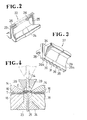
- the cutter 27 is now actuated to come down into engagement with and cut the upper legs Eb over a predetermined length of the stringer chain C as shown in Figure 5, in which instance the blades 28, 29 are disposed with their respective terminal ends 28a, 29a substantially registering with the upper legs Eb adjacent to the heel portions Ed of the endmost elements Ex on the respective tapes T, T as shown in Figure 8. This ensures freedom of those neighbouring coupling elements Ey immediately adjoining the endmost elements Ex from being inadvertently cut or impaired by the cutter 27.
- the length of the coupling elements E which has been cut is removed from the stringer chain C by the knock-out plate 25 as the latter makes a further upward movement clear across the level of the horizontal path of travel 13 as shown in Figure 6, thereby providing an element-free portion or gap G at predetermined intervals longitudinally along the stringer chain C for subsequent mounting of the slide fastener component parts in a manner well known in the art.
- Figure 9 shows a modification in which the die block 23 (24) has a flat top surface 37 devoid of guide grooves 26.
- Figure 10 shows another modification in which the punch 34 has as many positioning prongs 36 as to engage between each adjacent upper leg Eb of the coupling elements E.
Landscapes
- Slide Fasteners (AREA)
- Perforating, Stamping-Out Or Severing By Means Other Than Cutting (AREA)
- Treatment Of Fiber Materials (AREA)
- Auxiliary Devices For And Details Of Packaging Control (AREA)
Applications Claiming Priority (2)
| Application Number | Priority Date | Filing Date | Title |
|---|---|---|---|
| JP2194408A JPH0767403B2 (ja) | 1990-07-23 | 1990-07-23 | スライドファスナーチエーンのスペース部作成装置 |
| JP194408/90 | 1990-07-23 |
Publications (2)
| Publication Number | Publication Date |
|---|---|
| EP0468334A1 true EP0468334A1 (de) | 1992-01-29 |
| EP0468334B1 EP0468334B1 (de) | 1994-08-24 |
Family
ID=16324109
Family Applications (1)
| Application Number | Title | Priority Date | Filing Date |
|---|---|---|---|
| EP91111763A Expired - Lifetime EP0468334B1 (de) | 1990-07-23 | 1991-07-15 | Vorrichtung zur Entfernung eines Reissverschlusses |
Country Status (10)
| Country | Link |
|---|---|
| US (1) | US5103540A (de) |
| EP (1) | EP0468334B1 (de) |
| JP (1) | JPH0767403B2 (de) |
| KR (1) | KR930008623B1 (de) |
| BR (1) | BR9103208A (de) |
| CA (1) | CA2047132C (de) |
| DE (1) | DE69103595T2 (de) |
| ES (1) | ES2058996T3 (de) |
| HK (1) | HK104197A (de) |
| MY (1) | MY106360A (de) |
Families Citing this family (6)
| Publication number | Priority date | Publication date | Assignee | Title |
|---|---|---|---|---|
| JP3423479B2 (ja) * | 1995-05-31 | 2003-07-07 | ワイケイケイ株式会社 | スライドファスナーチェーンのスペース部におけるファスナーエレメント除去方法及びその装置 |
| JP3892262B2 (ja) * | 2001-10-01 | 2007-03-14 | Ykk株式会社 | スライドファスナーチェーンのスペース形成装置 |
| US7743512B1 (en) | 2004-11-08 | 2010-06-29 | Zipwall, Llc. | Plastic sheet cutter |
| CN102601750B (zh) * | 2011-12-29 | 2014-07-30 | 佛山市顺德区泰纶拉链有限公司 | 一种拉链头自动安装机的拉链头夹紧定位装置 |
| CN104349693B (zh) * | 2013-08-13 | 2017-11-14 | Ykk株式会社 | 空间形成装置 |
| CN107105836B (zh) * | 2015-01-05 | 2019-11-29 | Ykk株式会社 | 间隔形成装置 |
Citations (4)
| Publication number | Priority date | Publication date | Assignee | Title |
|---|---|---|---|---|
| FR2207664A1 (de) * | 1972-11-28 | 1974-06-21 | Yoshida Kogyo Kk | |
| US4131223A (en) * | 1977-12-05 | 1978-12-26 | Scovill Manufacturing Company | Apparatus for gapping a slide fastener |
| GB2159577A (en) * | 1984-05-01 | 1985-12-04 | Yoshida Kogyo Kk | Space forming device for slide fastener chain |
| FR2574637A1 (fr) * | 1984-12-15 | 1986-06-20 | Opti Patent Forschung Fab | Dispositif pour decouper des organes de fermeture dans une bande de fermetures a glissiere |
Family Cites Families (6)
| Publication number | Priority date | Publication date | Assignee | Title |
|---|---|---|---|---|
| US3611538A (en) * | 1968-02-24 | 1971-10-12 | Yoshida Kogyo Kk | Apparatus for continuously producing a slide fastener chain |
| JPS5820783B2 (ja) * | 1974-01-31 | 1983-04-25 | ワイケイケイ株式会社 | スライドフアスナ−チエ−ン ノ スペ−スサクセイホウホウ ト ソノソウチ |
| JPS58102608U (ja) * | 1981-12-29 | 1983-07-12 | ワイケイケイ株式会社 | 連続する噛合コイルエレメントを有するスライドフアスナ−チエンにスペ−ス部分を形成する装置 |
| JPS59115002A (ja) * | 1982-12-23 | 1984-07-03 | ワイケイケイ株式会社 | 合成樹脂製スライドファスナーチェーンと,その生産に用いる合成樹脂製連続スライドファスナーチェーンのスペース部形成用パンチ |
| JPS60114205A (ja) * | 1983-11-25 | 1985-06-20 | ワイケイケイ株式会社 | 隠しスライドファスナ−チェ−ンのスペ−ス形成方法及び装置 |
| JPH0529604Y2 (de) * | 1986-12-28 | 1993-07-29 |
-
1990
- 1990-07-23 JP JP2194408A patent/JPH0767403B2/ja not_active Expired - Fee Related
-
1991
- 1991-07-15 EP EP91111763A patent/EP0468334B1/de not_active Expired - Lifetime
- 1991-07-15 ES ES91111763T patent/ES2058996T3/es not_active Expired - Lifetime
- 1991-07-15 DE DE69103595T patent/DE69103595T2/de not_active Expired - Fee Related
- 1991-07-16 CA CA002047132A patent/CA2047132C/en not_active Expired - Fee Related
- 1991-07-19 US US07/733,162 patent/US5103540A/en not_active Expired - Lifetime
- 1991-07-19 MY MYPI91001306A patent/MY106360A/en unknown
- 1991-07-22 KR KR1019910012550A patent/KR930008623B1/ko not_active Expired - Fee Related
- 1991-07-23 BR BR919103208A patent/BR9103208A/pt not_active IP Right Cessation
-
1997
- 1997-06-26 HK HK104197A patent/HK104197A/en not_active IP Right Cessation
Patent Citations (4)
| Publication number | Priority date | Publication date | Assignee | Title |
|---|---|---|---|---|
| FR2207664A1 (de) * | 1972-11-28 | 1974-06-21 | Yoshida Kogyo Kk | |
| US4131223A (en) * | 1977-12-05 | 1978-12-26 | Scovill Manufacturing Company | Apparatus for gapping a slide fastener |
| GB2159577A (en) * | 1984-05-01 | 1985-12-04 | Yoshida Kogyo Kk | Space forming device for slide fastener chain |
| FR2574637A1 (fr) * | 1984-12-15 | 1986-06-20 | Opti Patent Forschung Fab | Dispositif pour decouper des organes de fermeture dans une bande de fermetures a glissiere |
Also Published As
| Publication number | Publication date |
|---|---|
| CA2047132C (en) | 1995-03-28 |
| HK104197A (en) | 1997-08-15 |
| ES2058996T3 (es) | 1994-11-01 |
| US5103540A (en) | 1992-04-14 |
| JPH0479902A (ja) | 1992-03-13 |
| JPH0767403B2 (ja) | 1995-07-26 |
| EP0468334B1 (de) | 1994-08-24 |
| KR920002069A (ko) | 1992-02-28 |
| DE69103595D1 (de) | 1994-09-29 |
| MY106360A (en) | 1995-05-30 |
| KR930008623B1 (ko) | 1993-09-11 |
| DE69103595T2 (de) | 1995-03-02 |
| BR9103208A (pt) | 1992-02-18 |
Similar Documents
| Publication | Publication Date | Title |
|---|---|---|
| US3852869A (en) | Method and apparatus for removing interlocking fastener elements from a slide fastener chain | |
| EP0396373B1 (de) | Verfahren und Vorrichtung zum Anbringen von oberen Endgliedern an einer Reissverschlusskette | |
| US5103540A (en) | Apparatus for gapping a stringer chain | |
| EP0488816B1 (de) | Verfahren und Vorrichtung zur Erzeugung von Lücken in einer Reissverschlusskette | |
| US4404722A (en) | Apparatus for forming a space section in a pair of continuous slide fastener stringers | |
| KR860000617B1 (ko) | 슬라이드 파스너 체인에 무엘레멘트 공간을 형성하는 방법 및 장치 | |
| EP0143387B1 (de) | Verfahren und Vorrichtung zur Erzeugung von Lücken in zwei fortlaufenden Streifen eines verdeckten Reissverschlusses | |
| JP3545164B2 (ja) | スライドファスナーチェーンのスペース形成方法及びその装置 | |
| US4232438A (en) | Method and apparatus for providing space sections in a continuous slide fastener chain | |
| EP0068317A1 (de) | Verfahren und Vorrichtung zur Befestigung von Verstärkungsmaterial an Reissverschlussbändern | |
| DE69020444T2 (de) | Verfahren zum Herstellen von gliedfreien Lücken in einer fortlaufenden Reissverschlusskette. | |
| CN1073846A (zh) | 拉链底链开口装置 | |
| EP0058882A1 (de) | Vorrichtung zum Herstellen von gliedfreien Lücken in einer fortlaufenden Reissverschlusskette | |
| KR880000594Y1 (ko) | 연속슬라이드 파스너에의 한쌍의 상지구 부착 장치 | |
| EP0171744B1 (de) | Vorrichtung zur Endfertigung eines Reissverschlussbandes mit einem Verstärkerstreifen | |
| US4831709A (en) | Method of an apparatus for removing coupling elements from a slide fastener stringer tape | |
| CA2067922C (en) | Method for forming element-free spaces in slide fastener chain | |
| KR900005992B1 (ko) | 상지구 부착장치 | |
| DE1082564B (de) | Vorrichtung zum Herstellen von gliedfreien Stellen bei Verschlussstreifen von aus fortlaufenden Windungen bestehenden Reissverschluessen | |
| GB2095744A (en) | Forming gaps in continuous slide fastener chains | |
| GB2064383A (en) | Apparatus and method for removing a section of coupling members from a continuous sliding clasp fastener stringer |
Legal Events
| Date | Code | Title | Description |
|---|---|---|---|
| PUAI | Public reference made under article 153(3) epc to a published international application that has entered the european phase |
Free format text: ORIGINAL CODE: 0009012 |
|
| AK | Designated contracting states |
Kind code of ref document: A1 Designated state(s): BE DE ES FR GB IT NL |
|
| ITCL | It: translation for ep claims filed |
Representative=s name: JACOBACCI CASETTA & PERANI S.P.A. |
|
| 17P | Request for examination filed |
Effective date: 19920429 |
|
| 17Q | First examination report despatched |
Effective date: 19930317 |
|
| GRAA | (expected) grant |
Free format text: ORIGINAL CODE: 0009210 |
|
| AK | Designated contracting states |
Kind code of ref document: B1 Designated state(s): BE DE ES FR GB IT NL |
|
| ET | Fr: translation filed | ||
| REF | Corresponds to: |
Ref document number: 69103595 Country of ref document: DE Date of ref document: 19940929 |
|
| ITF | It: translation for a ep patent filed | ||
| ITPR | It: changes in ownership of a european patent |
Owner name: CAMBIO RAGIONE SOCIALE;YKK CORPORATION |
|
| RAP2 | Party data changed (patent owner data changed or rights of a patent transferred) |
Owner name: YKK CORPORATION |
|
| REG | Reference to a national code |
Ref country code: FR Ref legal event code: CD |
|
| REG | Reference to a national code |
Ref country code: ES Ref legal event code: PC2A Owner name: YKK CORPORATION |
|
| NLT1 | Nl: modifications of names registered in virtue of documents presented to the patent office pursuant to art. 16 a, paragraph 1 |
Owner name: YKK CORPORATION TE TOKIO, JAPAN. |
|
| PLBE | No opposition filed within time limit |
Free format text: ORIGINAL CODE: 0009261 |
|
| 26N | No opposition filed | ||
| REG | Reference to a national code |
Ref country code: GB Ref legal event code: IF02 |
|
| PGFP | Annual fee paid to national office [announced via postgrant information from national office to epo] |
Ref country code: NL Payment date: 20050703 Year of fee payment: 15 |
|
| PGFP | Annual fee paid to national office [announced via postgrant information from national office to epo] |
Ref country code: DE Payment date: 20050707 Year of fee payment: 15 |
|
| PGFP | Annual fee paid to national office [announced via postgrant information from national office to epo] |
Ref country code: FR Payment date: 20050708 Year of fee payment: 15 |
|
| PGFP | Annual fee paid to national office [announced via postgrant information from national office to epo] |
Ref country code: GB Payment date: 20050713 Year of fee payment: 15 |
|
| PGFP | Annual fee paid to national office [announced via postgrant information from national office to epo] |
Ref country code: ES Payment date: 20050818 Year of fee payment: 15 |
|
| PGFP | Annual fee paid to national office [announced via postgrant information from national office to epo] |
Ref country code: BE Payment date: 20050914 Year of fee payment: 15 |
|
| PG25 | Lapsed in a contracting state [announced via postgrant information from national office to epo] |
Ref country code: GB Free format text: LAPSE BECAUSE OF NON-PAYMENT OF DUE FEES Effective date: 20060715 |
|
| PG25 | Lapsed in a contracting state [announced via postgrant information from national office to epo] |
Ref country code: BE Free format text: LAPSE BECAUSE OF NON-PAYMENT OF DUE FEES Effective date: 20060731 |
|
| PGFP | Annual fee paid to national office [announced via postgrant information from national office to epo] |
Ref country code: IT Payment date: 20060731 Year of fee payment: 16 |
|
| PG25 | Lapsed in a contracting state [announced via postgrant information from national office to epo] |
Ref country code: NL Free format text: LAPSE BECAUSE OF NON-PAYMENT OF DUE FEES Effective date: 20070201 Ref country code: DE Free format text: LAPSE BECAUSE OF NON-PAYMENT OF DUE FEES Effective date: 20070201 |
|
| GBPC | Gb: european patent ceased through non-payment of renewal fee |
Effective date: 20060715 |
|
| NLV4 | Nl: lapsed or anulled due to non-payment of the annual fee |
Effective date: 20070201 |
|
| REG | Reference to a national code |
Ref country code: FR Ref legal event code: ST Effective date: 20070330 |
|
| REG | Reference to a national code |
Ref country code: ES Ref legal event code: FD2A Effective date: 20060717 |
|
| BERE | Be: lapsed |
Owner name: *YKK CORP. Effective date: 20060731 |
|
| PG25 | Lapsed in a contracting state [announced via postgrant information from national office to epo] |
Ref country code: ES Free format text: LAPSE BECAUSE OF NON-PAYMENT OF DUE FEES Effective date: 20060717 |
|
| PG25 | Lapsed in a contracting state [announced via postgrant information from national office to epo] |
Ref country code: FR Free format text: LAPSE BECAUSE OF NON-PAYMENT OF DUE FEES Effective date: 20060731 |
|
| PG25 | Lapsed in a contracting state [announced via postgrant information from national office to epo] |
Ref country code: IT Free format text: LAPSE BECAUSE OF NON-PAYMENT OF DUE FEES Effective date: 20070715 |