EP0468338A2 - Appareil de broyage pour matières en vrac fibreuses ou granulaires comme des déchets - Google Patents
Appareil de broyage pour matières en vrac fibreuses ou granulaires comme des déchets Download PDFInfo
- Publication number
- EP0468338A2 EP0468338A2 EP91111817A EP91111817A EP0468338A2 EP 0468338 A2 EP0468338 A2 EP 0468338A2 EP 91111817 A EP91111817 A EP 91111817A EP 91111817 A EP91111817 A EP 91111817A EP 0468338 A2 EP0468338 A2 EP 0468338A2
- Authority
- EP
- European Patent Office
- Prior art keywords
- block
- knife block
- knife
- recesses
- toothed
- Prior art date
- Legal status (The legal status is an assumption and is not a legal conclusion. Google has not performed a legal analysis and makes no representation as to the accuracy of the status listed.)
- Granted
Links
Images
Classifications
-
- B—PERFORMING OPERATIONS; TRANSPORTING
- B02—CRUSHING, PULVERISING, OR DISINTEGRATING; PREPARATORY TREATMENT OF GRAIN FOR MILLING
- B02C—CRUSHING, PULVERISING, OR DISINTEGRATING IN GENERAL; MILLING GRAIN
- B02C18/00—Disintegrating by knives or other cutting or tearing members which chop material into fragments
- B02C18/06—Disintegrating by knives or other cutting or tearing members which chop material into fragments with rotating knives
- B02C18/14—Disintegrating by knives or other cutting or tearing members which chop material into fragments with rotating knives within horizontal containers
- B02C18/142—Disintegrating by knives or other cutting or tearing members which chop material into fragments with rotating knives within horizontal containers with two or more inter-engaging rotatable cutter assemblies
-
- B—PERFORMING OPERATIONS; TRANSPORTING
- B02—CRUSHING, PULVERISING, OR DISINTEGRATING; PREPARATORY TREATMENT OF GRAIN FOR MILLING
- B02C—CRUSHING, PULVERISING, OR DISINTEGRATING IN GENERAL; MILLING GRAIN
- B02C18/00—Disintegrating by knives or other cutting or tearing members which chop material into fragments
- B02C18/06—Disintegrating by knives or other cutting or tearing members which chop material into fragments with rotating knives
- B02C18/16—Details
- B02C18/18—Knives; Mountings thereof
- B02C18/182—Disc-shaped knives
- B02C18/184—Disc-shaped knives with peripherally arranged demountable cutting tips or elements
-
- C—CHEMISTRY; METALLURGY
- C05—FERTILISERS; MANUFACTURE THEREOF
- C05F—ORGANIC FERTILISERS NOT COVERED BY SUBCLASSES C05B, C05C, e.g. FERTILISERS FROM WASTE OR REFUSE
- C05F17/00—Preparation of fertilisers characterised by biological or biochemical treatment steps, e.g. composting or fermentation
- C05F17/90—Apparatus therefor
- C05F17/921—Devices in which the material is conveyed essentially horizontally between inlet and discharge means
- C05F17/939—Means for mixing or moving with predetermined or fixed paths, e.g. rails or cables
-
- Y—GENERAL TAGGING OF NEW TECHNOLOGICAL DEVELOPMENTS; GENERAL TAGGING OF CROSS-SECTIONAL TECHNOLOGIES SPANNING OVER SEVERAL SECTIONS OF THE IPC; TECHNICAL SUBJECTS COVERED BY FORMER USPC CROSS-REFERENCE ART COLLECTIONS [XRACs] AND DIGESTS
- Y02—TECHNOLOGIES OR APPLICATIONS FOR MITIGATION OR ADAPTATION AGAINST CLIMATE CHANGE
- Y02P—CLIMATE CHANGE MITIGATION TECHNOLOGIES IN THE PRODUCTION OR PROCESSING OF GOODS
- Y02P20/00—Technologies relating to chemical industry
- Y02P20/141—Feedstock
- Y02P20/145—Feedstock the feedstock being materials of biological origin
-
- Y—GENERAL TAGGING OF NEW TECHNOLOGICAL DEVELOPMENTS; GENERAL TAGGING OF CROSS-SECTIONAL TECHNOLOGIES SPANNING OVER SEVERAL SECTIONS OF THE IPC; TECHNICAL SUBJECTS COVERED BY FORMER USPC CROSS-REFERENCE ART COLLECTIONS [XRACs] AND DIGESTS
- Y02—TECHNOLOGIES OR APPLICATIONS FOR MITIGATION OR ADAPTATION AGAINST CLIMATE CHANGE
- Y02W—CLIMATE CHANGE MITIGATION TECHNOLOGIES RELATED TO WASTEWATER TREATMENT OR WASTE MANAGEMENT
- Y02W30/00—Technologies for solid waste management
- Y02W30/40—Bio-organic fraction processing; Production of fertilisers from the organic fraction of waste or refuse
Definitions
- the invention relates to a device for comminuting fibrous or granular piles such as waste with at least one rotor provided in a housing, from which a plurality of cutting tools project approximately radially, in particular with at least two rotors which delimit a feed gap with one another.
- a device for comminuting and processing waste materials such as waste is described in EP-PS 0 003 779 and has various deficiencies which, on the one hand, limit its service life or service life and, on the other hand, its efficiency.
- the radial beater bars serving as comminution tools wear out after a relatively short service life and then have to be broken out with considerable effort. Depending on the treatment, they are often closed after only a few days and are then no longer able to fulfill their task of shredding waste parts.
- Most of the items to be processed with the device contain highly lubricating components which not only wear out the batons very quickly, but also penetrate into the bearings and soon destroy them.
- the inventor has set itself the goal of improving the efficiency of a comminution device and, above all, of increasing its service life. It is very important to design the rotor in such a way that, above all, the comminution tools are not unusable too often, and this results in long interruptions in operation.
- toothed disks arranged side by side with a saw blade-like circumference form the rotor, the cutting edges of the toothed disk pointing in the direction of rotation each being formed by an edge of a block insert introduced into a groove.
- the grooves are undercut transversely to the direction of rotation and each take up a corresponding part of the block insert, which is held in a form-fitting manner, so that special fastening means are not actually required.
- the shape of the block insert is delimited by a cube or cuboid shape, four parallel edges defining flanks with flank sections inclined on both sides of a center line; From this center line, the flanks describe the counterpart to the undercut shape of the insert groove.
- flank sections are inclined at an angle of, for example, approximately 70 to the adjacent surface of the block insert, the choice of the angle of inclination or undercut depending on the stress on the block insert and the materials selected.
- the center line defines a plane of symmetry placed through two transverse notches of the block insert, on both sides of which the same block shapes exist, so that the block insert with both block parts determined by that middle plane can be inserted into the undercut groove.
- the transverse plane to the center line is also a plane of symmetry
- four block sections of the same shape are formed, each of which carries a cutting edge, which means that this block insert, which acts as a knife block, can be used four times.
- slits run in a diametral plane of the recesses in the walls surrounding them, preferably parallel to the cutting edges, and end as bag slots at a distance from the block surfaces.
- These slots bring with them a certain and adjustable flexibility of the metallic knife block, which is particularly important when clamping in the undercut groove; the two slots, which are temporarily arranged on the free surface of the knife block, can be closed by spacers, for example also by welding beads.
- the idea is to place the described crushing device or a corresponding device upstream of a conveying device of a compost heap, preferably a movable compost bridge spanning the latter - advantageously in combination with hollow spindles that can be inserted vertically into the compost heap from the compost bridge, perforated according to the invention and with its upper end to a liquid and / or air duct are connected.
- These hollow spindles is closed and their interior is connected according to the invention via a hollow shaft, a rotatable coupling and an air pipe to a blower, so that air can be injected into the compost heap, it is also possible to pass liquid optionally into the compost heap, thereby creating a strong ventilation and humidification of the compost heap is achieved during loosening.
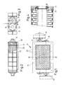
- a rotor cutting mill 10 has toothed disks 20 in a housing 12 on shafts 14 and 16, the drives of which are designated 18.
- the two shafts 14, 16 rotate in opposite directions, so that an inlet gap 19 is formed for the feed material falling into the housing 12 in the feed direction x and pre-shredded and drawn in above the toothed disks 20. Its vertical fall direction shows arrow direction x.
- a cutter bar 22 which can be adjusted in the vertical direction, that is to say can be adjusted relative to the conveyor gap between the toothed disks 20.
- 24 denotes an air gap between the rotating toothed disks 20 and a bearing group 26. This air gap 24 prevents damage to the bearing group 26, which can result from the fact that raw material is squeezed by the rotating toothed discs 20 and a fixed wear plate. The emerging raw material can be removed through an air gap, whereby a sandwich seal is achieved.
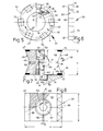
- the toothed disk body is a ring 30 with an axis bore 32 and a peripheral edge 34 designed in the manner of a saw disk.
- Each sawtooth tip of the side view according to FIG. 5 appears in front view as a sawtooth edge 35, from which a tooth front 36 extends. This delimits an isosceles triangle in cross section with a radial line R laid through the sawtooth edge 35 and thereby forms a central ridge line 37.
- the tooth flank 36 jumps back to the radial line R as the side wall of an undercut groove 38, the other side wall 39 of which is upward at one Edge 40 ends at which the next "saw tooth” begins.
- a blind hole 44 is provided in the groove deepest 42 in its transverse center.
- the undercut groove 38 receives a knife block 46, which in FIG. 7,8 is essentially cuboid with a height h of 75 mm, a width b of 90 mm and a length a of 115 mm, for example.
- Four parallel edges 47, 70 of this knife block 46 determine two flank surfaces 48, which are inclined on both sides of a plane through a center line M and are thus of cross-sectionally V-shaped, so that the knife block 46, according to the side view of FIG. 7, has dovetail-shaped contours on both sides owns.
- the angles of inclination w of the flank sections 48 a measure approximately 70 ′.
- the cross-sectionally tapering part of the knife block 46 corresponds in its contour to the shape of the tooth flank 36, so that a knife block 46 inserted into the groove 38 with one of its flank sections 48 a abuts that tooth flank 36, while the lower region of the other flank 48 of the knife block 46 nestles against the groove wall 39.
- the knife block 46 can thus be clamped in the groove 38 of the toothed disk 20.
- the knife block 46 has a central recess 50, which tapers somewhat conically from the surface 52 of the knife block 46 downward in an area i to a shoulder-like ring shoulder 54 of an inner radius e of 18 mm, from which a cylindrical bore 56 of the axial Length q (about 14 mm) starts.
- the center line M through the tip of the V-shaped cross section of the flanks 48 and through a pair of transverse notches 49 determines a plane of symmetry of the block shape, so that the cylindrical bore 56 on the other side of this plane of symmetry into a towards the lower surface 53 of the knife block 46 widening recess 58 merges, which receives a threaded bushing 60.
- FIG. 7,8 shows a screw bolt 62 with an internal hexagon head 63 resting in that recess 50; the latter sits on the ring shoulder 54 when the shaft 64 of the screw bolt 62 in its threaded bushing 60 is screwed in and engages with its free end 65 in the described sack lock 44.
- the screw bolt 62 thus has the function of a locking member, on the other hand, it serves to clamp the knife block 46 in the undercut groove 38; In the area of the two recesses 50, 58, the knife block 46 is slit in a diametral plane E through the screw axis A, in another embodiment it is severed, that is, divided into two halves.
- strip-shaped hard metal inserts 68 can be seen, three of which gently rest against the groove walls 36, 39 and the tooth flank 36, while the knife block edge designated 70 in FIG Forming or cutting edge of the knife block 46 forms.
- a circle is indicated by K as the geometric location of all knife block edges 70
- circle K 1 is the geometric location of the center points of the knife blocks 46.
- spacer strips 72 are inserted into the upwardly directed slots 66, which prevent the slot 66 from being narrowed by external forces.
- welding beads can also be arranged.
- toothed disk 20 An embodiment of the toothed disk 20 is not shown, in which the individual knife blocks 46 are screwed in, for which purpose a special holder (not shown) is present in the individual knife blocks 46; it is not possible to screw them tightly in the individual toothed disks 20, since excessive forces act on the screws and threads; If the thread is destroyed, the tooth lock washer can no longer be repaired.
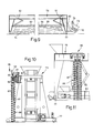
- the rotor cutting mill 10 is connected upstream of a portal-like compost bridge 76 which can be moved over a compost heap 74 and which can be moved on trolleys 77 on both sides of the compost heap 74.
- a feed hopper 78 with feed plunger 79 is attached to the rotor cutting mill 10.
- These units and the rotor cutting mill 10, which is gripped by a stick conveyor 80, for example a chain, belt or web conveyor, are attached to the compost bridge 76.
- the steep conveyor 80 conveys the shredded pile into a telescopic shaft 81, from which it falls onto a cross conveyor 83 with a scraper 84 over a sieve tray 85, which is height-adjustable on lifting devices 82.
- Fig. 10 shows a loosening frame 86 with two - side holes 87 -spindle 88, the bottom of which is closed.
- the interior of this hollow spindle / n 88 is connected to a fan 92 via a hollow shaft 89, a rotatable coupling 90 and an air pipe 91.
- a lockable water line 93 also leads into the hollow shaft 89 in order to selectively inject liquid into the air flow.
Landscapes
- Engineering & Computer Science (AREA)
- Chemical & Material Sciences (AREA)
- Food Science & Technology (AREA)
- General Chemical & Material Sciences (AREA)
- Life Sciences & Earth Sciences (AREA)
- Biochemistry (AREA)
- Biotechnology (AREA)
- Chemical Kinetics & Catalysis (AREA)
- Health & Medical Sciences (AREA)
- Microbiology (AREA)
- Molecular Biology (AREA)
- Organic Chemistry (AREA)
- Crushing And Pulverization Processes (AREA)
- Processing Of Solid Wastes (AREA)
- Disintegrating Or Milling (AREA)
- Filling Or Emptying Of Bunkers, Hoppers, And Tanks (AREA)
Applications Claiming Priority (2)
| Application Number | Priority Date | Filing Date | Title |
|---|---|---|---|
| DE4023710 | 1990-07-26 | ||
| DE19904023710 DE4023710A1 (de) | 1990-07-26 | 1990-07-26 | Vorrichtung zum zerkleinern von faserigem oder granulatartigem haufwerk wie muell |
Publications (3)
| Publication Number | Publication Date |
|---|---|
| EP0468338A2 true EP0468338A2 (fr) | 1992-01-29 |
| EP0468338A3 EP0468338A3 (en) | 1992-07-01 |
| EP0468338B1 EP0468338B1 (fr) | 1996-04-03 |
Family
ID=6411030
Family Applications (1)
| Application Number | Title | Priority Date | Filing Date |
|---|---|---|---|
| EP19910111817 Expired - Lifetime EP0468338B1 (fr) | 1990-07-26 | 1991-07-16 | Appareil de broyage pour matières en vrac fibreuses ou granulaires comme des déchets |
Country Status (3)
| Country | Link |
|---|---|
| EP (1) | EP0468338B1 (fr) |
| AT (1) | ATE136234T1 (fr) |
| DE (2) | DE4023710A1 (fr) |
Cited By (7)
| Publication number | Priority date | Publication date | Assignee | Title |
|---|---|---|---|---|
| DE9217598U1 (de) * | 1992-12-23 | 1993-03-04 | Unterwurzacher Patentverwertungsgesellschaft M.B.H., Kuchl | Zerkleinerungsscheibe |
| EP0521357A3 (en) * | 1991-07-04 | 1993-03-31 | Daneco Danieli Ecologia Spa | Machine to aerate compost in heaps |
| WO1994021577A1 (fr) * | 1993-03-25 | 1994-09-29 | Xeros Handelsgesellschaft M.B.H. | Agencement de compostage |
| WO2000014031A1 (fr) * | 1998-09-04 | 2000-03-16 | Linde Brv Biowaste Technologies Ag | Installation de compostage |
| EP2598248A1 (fr) * | 2010-07-26 | 2013-06-05 | Hugo Vogelsang Maschinenbau GmbH | Déchiqueteur à double arbre avec jeu de couteaux de coupe interchangeable |
| CN107059549A (zh) * | 2017-05-31 | 2017-08-18 | 河南高远公路养护设备股份有限公司 | 纤维剪切装置的剪切轮 |
| CN108311059A (zh) * | 2018-03-13 | 2018-07-24 | 占学宽 | 一种有机肥造粒机 |
Families Citing this family (1)
| Publication number | Priority date | Publication date | Assignee | Title |
|---|---|---|---|---|
| DE4240444C2 (de) * | 1992-12-02 | 1995-08-24 | Lindemann Maschfab Gmbh | Rotorschere zum Zerkleinern von insbesondere sperrigen Abfällen |
Family Cites Families (4)
| Publication number | Priority date | Publication date | Assignee | Title |
|---|---|---|---|---|
| GB896928A (en) * | 1959-12-17 | 1962-05-23 | Unipulver Ltd | Improvements in grinding or pulverizing mills |
| DE1607475A1 (de) * | 1967-07-29 | 1969-09-18 | Heinrich Dreher | Zerkleinerungsmaschine mit tangential auf einer umlaufenden Trommel befestigten Messerkoerpern |
| FR2542632B1 (fr) * | 1983-03-18 | 1986-03-28 | Realisa Thermiques Et | Broyeur pour dechets |
| US4687144A (en) * | 1986-06-13 | 1987-08-18 | Irwin Research & Development, Inc. | Apparatus for comminuting waste materials |
-
1990
- 1990-07-26 DE DE19904023710 patent/DE4023710A1/de not_active Withdrawn
-
1991
- 1991-07-16 DE DE59107643T patent/DE59107643D1/de not_active Expired - Fee Related
- 1991-07-16 EP EP19910111817 patent/EP0468338B1/fr not_active Expired - Lifetime
- 1991-07-16 AT AT91111817T patent/ATE136234T1/de not_active IP Right Cessation
Cited By (7)
| Publication number | Priority date | Publication date | Assignee | Title |
|---|---|---|---|---|
| EP0521357A3 (en) * | 1991-07-04 | 1993-03-31 | Daneco Danieli Ecologia Spa | Machine to aerate compost in heaps |
| DE9217598U1 (de) * | 1992-12-23 | 1993-03-04 | Unterwurzacher Patentverwertungsgesellschaft M.B.H., Kuchl | Zerkleinerungsscheibe |
| WO1994021577A1 (fr) * | 1993-03-25 | 1994-09-29 | Xeros Handelsgesellschaft M.B.H. | Agencement de compostage |
| WO2000014031A1 (fr) * | 1998-09-04 | 2000-03-16 | Linde Brv Biowaste Technologies Ag | Installation de compostage |
| EP2598248A1 (fr) * | 2010-07-26 | 2013-06-05 | Hugo Vogelsang Maschinenbau GmbH | Déchiqueteur à double arbre avec jeu de couteaux de coupe interchangeable |
| CN107059549A (zh) * | 2017-05-31 | 2017-08-18 | 河南高远公路养护设备股份有限公司 | 纤维剪切装置的剪切轮 |
| CN108311059A (zh) * | 2018-03-13 | 2018-07-24 | 占学宽 | 一种有机肥造粒机 |
Also Published As
| Publication number | Publication date |
|---|---|
| EP0468338A3 (en) | 1992-07-01 |
| DE4023710A1 (de) | 1992-01-30 |
| EP0468338B1 (fr) | 1996-04-03 |
| DE59107643D1 (de) | 1996-05-09 |
| ATE136234T1 (de) | 1996-04-15 |
Similar Documents
| Publication | Publication Date | Title |
|---|---|---|
| DE69608918T3 (de) | Zerkleinerungsvorrichtung | |
| DE68905063T2 (de) | Zerkleinerer. | |
| DE3932345C2 (fr) | ||
| DE2641370C2 (de) | Gerät zum Vernichten von Mikrofilmen und dergleichen | |
| EP0529221B1 (fr) | Dispositif de broyage | |
| DE3807983C2 (de) | Vorrichtung zum Zerkleinern | |
| EP0468338B1 (fr) | Appareil de broyage pour matières en vrac fibreuses ou granulaires comme des déchets | |
| DE2256267C3 (de) | Mit Scherwirkung arbeitender Zerkleinerer | |
| DE4242740A1 (de) | Zerkleinerungsmaschine | |
| EP1071342A1 (fr) | Dispositif destine a dechiqueter des substances organiques | |
| DE2919321A1 (de) | Schneidsatz fuer einen fleischwolf | |
| EP0620762B1 (fr) | Broyeur et element tranchant pour broyeur | |
| EP0801975A1 (fr) | Dispositif pour le traitement des déchets organiques | |
| EP0956902B1 (fr) | Dispositif de montage de couteaux sur l'arbre coupant d'un appareil désintégrateur | |
| WO1986001580A1 (fr) | Tremie de chargement pour usines d'incineration d'ordures | |
| DE3908395C2 (de) | Vorrichtung zum Zerkleinern von Rest- und Abfallhölzern | |
| DE3611691A1 (de) | Zerkleinerungsvorrichtung | |
| EP1362638B1 (fr) | Broyeur pour le broyage de matériau | |
| AT398711B (de) | Zylindrischer rotor | |
| DE4443727C2 (de) | Sägemaschine mit Spiralscheiben zum Herstellen von Holzblöcken und Schneiden für solche Spiralscheiben | |
| EP0956901A1 (fr) | Arbre coupant muni d'éléments coupants pour appareil désintégrateur | |
| DE4005647A1 (de) | Restholzzerkleinerungsmaschine | |
| DE2751958C2 (fr) | ||
| DE10037108A1 (de) | Schneidevorrichtung | |
| DE20216056U1 (de) | Vorrichtung zum Zerkleinern von Aufgabegut |
Legal Events
| Date | Code | Title | Description |
|---|---|---|---|
| PUAI | Public reference made under article 153(3) epc to a published international application that has entered the european phase |
Free format text: ORIGINAL CODE: 0009012 |
|
| AK | Designated contracting states |
Kind code of ref document: A2 Designated state(s): AT BE CH DE DK ES FR GB GR IT LI LU NL SE |
|
| RBV | Designated contracting states (corrected) |
Designated state(s): AT CH DE FR GB IT LI NL SE |
|
| PUAL | Search report despatched |
Free format text: ORIGINAL CODE: 0009013 |
|
| AK | Designated contracting states |
Kind code of ref document: A3 Designated state(s): AT BE CH DE DK ES FR GB GR IT LI LU NL SE |
|
| 17P | Request for examination filed |
Effective date: 19921208 |
|
| 17Q | First examination report despatched |
Effective date: 19940121 |
|
| GRAA | (expected) grant |
Free format text: ORIGINAL CODE: 0009210 |
|
| AK | Designated contracting states |
Kind code of ref document: B1 Designated state(s): AT CH DE FR GB IT LI NL SE |
|
| PG25 | Lapsed in a contracting state [announced via postgrant information from national office to epo] |
Ref country code: NL Free format text: LAPSE BECAUSE OF FAILURE TO SUBMIT A TRANSLATION OF THE DESCRIPTION OR TO PAY THE FEE WITHIN THE PRESCRIBED TIME-LIMIT Effective date: 19960403 Ref country code: GB Effective date: 19960403 Ref country code: FR Effective date: 19960403 |
|
| REF | Corresponds to: |
Ref document number: 136234 Country of ref document: AT Date of ref document: 19960415 Kind code of ref document: T |
|
| REF | Corresponds to: |
Ref document number: 59107643 Country of ref document: DE Date of ref document: 19960509 |
|
| ITF | It: translation for a ep patent filed | ||
| PG25 | Lapsed in a contracting state [announced via postgrant information from national office to epo] |
Ref country code: SE Effective date: 19960703 |
|
| PG25 | Lapsed in a contracting state [announced via postgrant information from national office to epo] |
Ref country code: LI Effective date: 19960731 Ref country code: CH Effective date: 19960731 |
|
| EN | Fr: translation not filed | ||
| NLV1 | Nl: lapsed or annulled due to failure to fulfill the requirements of art. 29p and 29m of the patents act | ||
| GBV | Gb: ep patent (uk) treated as always having been void in accordance with gb section 77(7)/1977 [no translation filed] |
Effective date: 19960403 |
|
| PLBE | No opposition filed within time limit |
Free format text: ORIGINAL CODE: 0009261 |
|
| STAA | Information on the status of an ep patent application or granted ep patent |
Free format text: STATUS: NO OPPOSITION FILED WITHIN TIME LIMIT |
|
| REG | Reference to a national code |
Ref country code: CH Ref legal event code: PL |
|
| 26N | No opposition filed | ||
| PGFP | Annual fee paid to national office [announced via postgrant information from national office to epo] |
Ref country code: AT Payment date: 19980129 Year of fee payment: 7 |
|
| PG25 | Lapsed in a contracting state [announced via postgrant information from national office to epo] |
Ref country code: AT Free format text: LAPSE BECAUSE OF NON-PAYMENT OF DUE FEES Effective date: 19980716 |
|
| PGFP | Annual fee paid to national office [announced via postgrant information from national office to epo] |
Ref country code: DE Payment date: 20010911 Year of fee payment: 11 |
|
| PG25 | Lapsed in a contracting state [announced via postgrant information from national office to epo] |
Ref country code: DE Free format text: LAPSE BECAUSE OF NON-PAYMENT OF DUE FEES Effective date: 20030201 |
|
| PG25 | Lapsed in a contracting state [announced via postgrant information from national office to epo] |
Ref country code: IT Free format text: LAPSE BECAUSE OF NON-PAYMENT OF DUE FEES;WARNING: LAPSES OF ITALIAN PATENTS WITH EFFECTIVE DATE BEFORE 2007 MAY HAVE OCCURRED AT ANY TIME BEFORE 2007. THE CORRECT EFFECTIVE DATE MAY BE DIFFERENT FROM THE ONE RECORDED. Effective date: 20050716 |