EP0468402A2 - Système et méthode de recouvrement pour des suites de caractères - Google Patents
Système et méthode de recouvrement pour des suites de caractères Download PDFInfo
- Publication number
- EP0468402A2 EP0468402A2 EP91112240A EP91112240A EP0468402A2 EP 0468402 A2 EP0468402 A2 EP 0468402A2 EP 91112240 A EP91112240 A EP 91112240A EP 91112240 A EP91112240 A EP 91112240A EP 0468402 A2 EP0468402 A2 EP 0468402A2
- Authority
- EP
- European Patent Office
- Prior art keywords
- matching
- state
- specified pattern
- character
- outputted
- Prior art date
- Legal status (The legal status is an assumption and is not a legal conclusion. Google has not performed a legal analysis and makes no representation as to the accuracy of the status listed.)
- Granted
Links
Images














Classifications
-
- G—PHYSICS
- G06—COMPUTING OR CALCULATING; COUNTING
- G06F—ELECTRIC DIGITAL DATA PROCESSING
- G06F16/00—Information retrieval; Database structures therefor; File system structures therefor
- G06F16/90—Details of database functions independent of the retrieved data types
- G06F16/903—Querying
- G06F16/90335—Query processing
- G06F16/90344—Query processing by using string matching techniques
Definitions
- the present invention relates generally to an information processing system. More particularly, the invention is concerned with a search term matching (or collating) technique in an information or character string retrieving (searching) system for making decision en bloc as to whether a set of plural character strings which are specified or designated for search or retrieval is present in an text composed of characters or character strings and subjected to retrieval.
- search term matching or collating technique in an information or character string retrieving (searching) system for making decision en bloc as to whether a set of plural character strings which are specified or designated for search or retrieval is present in an text composed of characters or character strings and subjected to retrieval.
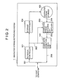
- a character string retrieving system denoted generally by a numeral 1 includes a search or retrieval controller 101 which is in charge of overall control of the whole retrieval (search) system as well as communications or transactions with a host computer (not shown). More specifically, the retrieval controller 101 receives a retrieval (serch) request 201 from the host computer and analyzes the request to thereby send retrieval information 202 (i.e. information for search or retrieval) to a character string matching or collating unit 200 (also referred to as the matcher) and a composite condition check unit 103. Further, the retrieval controller 101 controls a storage controller 104 for allowing the character string matching unit 200 to read out character string data 204 from a character string data storage 105.
- a retrieval (serch) request 201 from the host computer and analyzes the request to thereby send retrieval information 202 (i.e. information for search or retrieval) to a character string matching or collating unit 200 (also referred to as the matcher) and a composite condition check unit
- the character string matching circuit 200 checks the input character string data 204 as to presence of a character string which coincides with a serch term or character string designated by the retrieval request 201.
- information 205 for identifying the character string of interest is outputted to the composite condition check circuit 103.
- the composite condition check circuit 103 checks whether logical conditions including logical ANDing(s) and/or ORing(s) which are also designated by the retrieval request 201 can be satisfied or not.
- the identification information of the relevant document as well as the content or text data of the document are sent back to the host computer as the retrieval or search result 206.
- the character string matching circuit of the prior art shown in this figure is composed of a character code register 211, a state transition table 220, a state ID (identification) number register 250 and a matching ID table 260.
- an automaton for performing matching or collation of search terms (i.e. chracter strings specified for retrieval) in the state transition table 220.
- the state number 0 representing the initialized state of the automaton is placed in the state number register 250.
- the state number placed in the register 250 is referred to as the current state number and denoted by a reference numeral 305.
- the matching operation starts from loading of a character in the character code register 211 from an input character string (input text) 204 on a character-by-character basis.
- access is made to the state transition table 220 by using as the addresses therefor a character code 302 outputted from the character code register 211 and the current state number 305 outputted from the state number register 250, respectively, as a result of which a succeeding state number 303 indicating the state to which state transition is next to be made is read out from the state transition table 220.
- This succeeding state number 303 is held as a renewed or updated current state number as indicated at 305.
- the matching ID (identification) table 260 is accessed by using as the addresses therefor the current state number 305 outputted from the state number register 250 and the input character code 302, whereby the identification number or identifier of the search term is read out as a result of the matching as indicated at 205.
- the identification number or identifier for the search term as read out from the matching ID table 260 is "0" (zero)
- the character string matching can be accomplished.
- Fig. 4 there is shown a state transition diagram of an automaton for matching two search terms, i.e. "DOG” and "CAT", inputted by a searcher.
- circles represent the states of the automaton, respectively, while arrows represent state transitions, respectively.
- characters affixed to the arrows represent input characters which bring about the associated state transitions, respectively.
- numerals shown as enclosed by the circles indicate the state numbers, respectively.
- the state 0 (zero) is the initial state of the automaton under consideration. For all the input characters for which no specific entries are found in conjunction with the transition, the automaton always assumes the initial state 0.
- the arrows 404 and 405 each affixed with a slash mark "/" represent the state transitions indicating that matching has been accomplished for "DOG” and "CAT", respectively. More specifically, the arrow 404 representing the state transition from the state 2 indicates that the matching has been accomplished for the term "DOG”. On the other hand, the arrow 405 representing the transition from the state 4 indicates that "CAT" has been matched or collated.
- Figs. 5 and 6 of the accompanying drawings show exemplary structures of the state transition table 220 storing the automaton shown in Fig. 4 and the matching ID table 260, respectively.
- the state transition table 220 is implemented in such a structure which allows access thereto with the input character code 302 and the current state number 305 of the automaton under consideration. More specifically, when the current state number 305 has a value 0 (zero) with the input character code 302 being "D", the state number 1 (one) corresponding to 0 (zero) and "D" is outputted as the succeeding state number 303 to which the automaton should make transition in succession.
- the matching ID table 260 stores the information that matching of the search terms has been accomplished as well as the information resulting from the matching as indicated by the arrows 404 and 405 in Fig. 4.
- the identification numbers of the search terms (hereinafter also referred to as the matching identifiers) are stored in the matching ID table 260 which can be addressed with the current state number and the trailing character code of the search term upon occurrence of the state transition in response to appearance of the trailing character thereof (e.g. the table 260 is addressed with the state 2 and the character "G" in the case of the search term "DOG” illustrated in Fig. 4).
- 1 one is stored as the matching identifier.
- Numerical values other than 0 (zero) represent the identification numbers or identifiers of the search term. By assigning the numerical values other than 0 (zero) to the matching identifiers while assigning 0 (zero) to those other than the objectives for matching, it is possible to discriminatively identify the output of the matching or collation as performed.
- the areas of the matching ID table 260 which are effectively made use of are only those which correspond to the transitions occurring upon appearance of the trailing characters of the search terms, as can be seen from Fig. 6.
- the matching ID table has undesirably to be implemented with such a capacity which corresponds to a product of the number of different types of characters and the number of the states in order to store only a small amount of search term identification information.
- a memory of a large capacity is required for the matching ID table inefficiently.
- the number of the slots which can effectively be used amounts actually to no more than 64 slots, i.e. only about one thousandth of all the slots.
- the matching ID table of the character string retrieving system disclosed in the J-P-A-60-105039 makes it necessary to use a memory of an enormously large capacity even for the matching of only a small number of the search terms, which ultimately leads to an expensive and large scale character string retrieving system, presenting a serious problem.
- Another problem of the prior art character string retrieving system can be seen in that since one slot of the matching ID table can store no more than one matching identifier of the search term, it is impossible to cope with a multiple matching processing.
- Figs. 8 and 9 of the accompanying drawings show, respectively, the contents of the state transition table 220 and the matching ID table 260 which correspond to the automaton shown in Fig. 7.
- the term “DOG” is a substring constituting a so-called trailing character substring of "HOTDOG”. Accordingly, when an input text containing "HOTDOG” is inputted, not only “HOTDOG” but also "DOG” will have to be outputted as the result of the matching. In other words, upon inputting of the trailing character “G” of "HOTDOG", the identification numbers for the two terms “HOTDOG” and “DOG” have to be outputted.
- the scheme in which a plurality of terms are matched through the state transition process for a single input text, as mentioned above, is referred to as the multiple matching. Further, the terms susceptible or subjected to such multiple matching may be said as having "multiple matching relation".
- the slot of the matching ID table 260 corresponding to the current state number 7 and the character code "G" can accommodate no more than one matching identifier, i.e. only the result of matching for "HOTDOG".
- the prior art character string retrieving system suffers from an additional problem that the aforementioned multiple matching processing can not be carried out, to a serious disadvantage.
- a second object of the present invention is to provide a character string retrieving system which is capable of outputting correct matching results even for the multiple matching without incurring any omission of matching for the terms having the multiple matching relation.
- a character string retrieving system which comprises an automaton including a matching ID table containing as entries thereof the automaton state numbers which can be determined in consideration of the number of the transition states and the types or species of character codes, wherein an automaton state is newly created as a destination state for the state transition occurring upon appearance of a trailing character of a term to be retrieved instead of using the initial state as the transition destination state for the trailing character, for thereby allowing the capacity of a memory constituting the matching ID table to be reduced.
- the newly created state is utilized for storing the result of the matching. It is thus sufficient for the matching ID table to store the result of matching in the newly created state at the entry determined by a corresponding state number.
- a character string retrieving system in which identifiers for search terms (terms to be retrieved) which are to undergo the matching processing are each represented by one bit information, wherein a group of corresponding flags is stored in one slot of the matching ID table in order to exclude omission of any search term from the matching even upon occurrence of multiple matching for which a plurality of results of matching have to be outputted simultaneously.
- a character string retrieving system comprising an automaton which is so configured as to reduce the memory capacity of the matching ID table by containing as entries therein the state numbers determined on the basis of the types or kinds of the character codes and the number of the automaton states and in which a new state is provided to serve as a transition destination state instead of the initial state for the state transition occurring upon appearance of a trailing character constituting a trailing part of the search term to thereby allow the result of matching to be stored in the newly created state, wherein with a view to performing matching for the search terms without any omission thereof upon occurrence of the multiple matching requiring output of the matching results for a plurality of search terms simultaneously, the identifiers of the search terms to be matched are each represented by one bit information and a group of corresponding flags are stored in one slot of the matching ID table having the state numbers as the entries thereof.
- a character string retrieving system comprising an automaton which is so configured as to reduce the memory capacity of the matching ID table by containing therein as the entries the state numbers determined on the basis of the kinds of the character codes and the number of the automaton states and in which a new state is created to serve as a destination state for the transition occurring upon appearance of a trailing character constituting a trailing part of the search term to thereby allow the result of matching to be stored in the newly created state instead of the initial state,
- a character string retrieving system which comprises
- a character string retrieving system In a character string retrieving system according to a seventh aspect of the invention, only the matching output dedicated state is used as the state for outputting the result of matching in contrast to the character string retrieving system according to the sixth aspect of the invention in which the normal state and the matching output dedicated state are used for outputting the result of matching.
- a character string retrieving system which comprises
- the concept of the invention underlying the character string retrieving system according to the first aspect of the invention resides in that the number of the slots required for the matching result table can be reduced from "maximum number of the states" multiplied with "the number of types of the character codes" to the maximum state number by virtue of the automaton of such arrangement that the destination state of transition brought about by the trailing character of the search term is newly created instead of using the initial state to this end, wherein the matched term identifier is stored in the newly created state. Further, the matched term identifier of the search term is stored in the slot of the matching result table which corresponds to the newly created state.
- the matching ID table can be implemented in a structure which can be addressed with the state numbers, which means that the number of the slots corresponds to the maximum state number which is smaller than the memory capacity otherwise required, whereby there can be realized the character string retrieving system of a compact or reduced size.
- the identifiers of the search terms to be matched are each represented by one bit information so that one slot of the matching ID table can store a plurality of the search term identifiers in order to avoid the omission of any term from the matching upon occurrence of the multiple matching event where simultaneous output of the matching results for a plurality of search terms is required.
- the bit n of the slot for storing the matched term identifiers and the n-th search term matching flag there can be outputted the matched term identifiers simultaneously for a plurality of search terms.
- a plurality of relevant search term identifiers can simultaneously be outputted as the bit information.
- the multiple matching processing circuit makes decision as to whether the matching to be performed is the multiple matching on the basis of the matched term identifiers sent from the matching ID table while consulting the multiple matching table.
- the multiple matching processing circuit outputs as the matching result the matched term identifiers for the search terms which bear a multiple matching relation to one another.
- the multiple matching table is accessed by using the matched term identifier as the address, wherein the matched term identifiers for the search terms to undergo the multiple matching are stored at that address together with a next data address with which the multiple matching table is to be accessed upon succeeding reference to that table, whereby continuous addressing scheme can be realized.
- the concept underlying the character string retrieving system according to the fourth aspect of the invention is seen in that in order to decrease the slot number of the matching ID table from a number corresponding to "maximum state numbers" multiplied with "the number of types of character codes” to the maximum state number while assuring the avoidance of omission of any search terms from matching upon occurrence of the multiple matching where the matching results for a plurality of search terms have to be simultaneously outputted, automaton is generated in such configuration that the destination state for the state transition brought about by the trailing character of the search term is newly created instead of using the initial state to this end, wherein the matched term identifier is stored in the newly created state. Further, the matched term identifiers are stored in the slot of the matching ID table which corresponds to the abovementioned newly created state.
- the identifier of the search term to be matched is represented by one bit information, wherein a plurality of matched term identifiers are stored in one slot of the matching ID table.
- a plurality of matched term identifiers are stored in one slot of the matching ID table.
- the matching ID table is so configured as to be addressed with the state number, the number of slots corresponds to the maximum number of the states and can be decreased to a number considerably smaller than the memory capacity which would otherwise be required.
- the character retrieving system of a compact size.
- the concept underlying the character string retrieving system according to the fifth aspect of the invention is seen in that in order to decrease the slot number of the matching ID table from a number corresponding to a product of "maximum state numbers" multiplied with "the number of types of character codes” to the maximum state number while assuring the avoidance of omission of any search terms from matching upon occurrence of the multiple matching where the results of matching for a plurality of search terms have to be simultaneously outputted, automaton is generated in such configuration that the destination state for the state transition brought about by the trailing character of the search term is newly created instead of using the initial state to this end, wherein the matched term identifier is stored in the newly created state. Further, the matched term identifier is stored in the slot of the matching ID table which corresponds to the abovementioned newly created state.
- the multiple matching processing circuit makes decision as to whether the matching to be performed is the multiple matching on the basis of the matched term identifiers sent from the matching ID table by consulting the multiple matching table. In case the multiple matching is to be performed, the multiple matching processing circuit outputs as the result of matching the matched term identifiers for the search terms which bear the multiple matching relation to one another.
- the multiple matching table is accessed by using the matched term identifier as the address, wherein the matched term identifiers for the search terms to undergo the multiple matching are stored at that address together with a next data address with which the multiple matching table is to be accessed upon making succeeding reference to that table, whereby a continuous addressing scheme is realized.
- the matched term identifiers of a plurality of search terms bearing a multiple matching relation to one another can successively be outputted.
- the matching ID table is so implemented as to be addressed with the state number, the number of the slots does not exceed the maximum number of the automaton states and hence the memory capacity can correspondingly be reduced, which can lead to miniaturization of the character string retrieving system.
- a specified matching automaton is stored in the state transition table, and the initial state number of the automaton is placed in the state number register as the current state number.
- the matching operation begins, starting from the loading of an input text in the character code register on a character-by-character basis.
- the state transition table is accessed by using as the address the current state number stored in the state number register and a character code stored in the character code selector, whereby a succeeding state number is outputted from the state transition table.
- the matching ID table is also accessed by using as the address the current state number and the character code, which results in that the matching identifier and the multiple matching flag are outputted from the matching ID table.
- the matching identifier of "0" (zero) indicates that no matching has been found with a search term of concern. Subsequently, the succeeding state number is stored in the state number register as the updated current state number.
- the multiple matching flag as outputted is "0" (zero)
- the operation mentioned above is repetitively performed. In the case where the multiple matching flag is "1", operation described below is carried out.
- the character code selector continues to hold the character code already stored therein without any new character code being inputted to the character code selector.
- the state transition table and the matching ID table are accessed, as a result of which there are outputted the succeeding state number, the matching identifier and the multiple matching flag.
- the initial state number is placed in the initial state number register.
- the initial state transition flip-flop When the value set at the initial state transition flip-flop is "1", this indicates that the destination state for transition is the initial state. On the other hand, when the value set at that flip-flop is "0", this indicates that the transition destination state is other than the initial state. For starting the state transition from the initial state, the initial state transition flip-flop is set to "1" " as initialization.
- the comparing operation begins, starting from the inputting of an input text to the character code register on a character-by-character basis.
- the character code which is outputted from the character code register is sent to the character code selector. Since the matching output dedicated state flip-flop is set to "0", indicating that the current state is not the matching output dedicated state, the character code is sent out to the state transition table from the character code selector.
- the state transition table is accessed by using as address the character code and the initial state number. Through this access, there are read out from the state transition table the matching output dedicated state flag, the initial state transition flag and the succeeding state number, respectively. At that time, the value "0" placed in the matching output dedicated state flip-flop is sent out to the last matching output dedicated flip-flop. Thus, it is indicated that the current state is the normal state.
- the matching output dedicated state flag read out from the state transition table is stored in the matching output dedicated state flip-flop while the initial state transition flag as read out is stored in the initial state transition flip-flop.
- the current state number stored in the state number register is selected by the current state selector to be subsequently outputted to the state transition table as the current state number.
- the value of the initial state transition flip-flop is "1"
- the initial state number placed in the initial state number register is selected by the current state number selector to be outputted to the state transition table as the current state number, because the last matching output dedicated state flip-flop is set to "0".
- the matched term identifier register is loaded with the matched term identifier along with an offset for reading out from the state transition table a slot which stores therein the next succeeding state number or the matched term identifier and the offset in the matching output dedicated state.
- the matching identifier is outputted as the result of the matching processing, while the offset is sent to the adder.
- the current state selector selects the last succeeding state number outputted from the state number register as the current state number which is then outputted to the state transition table as the current state number.
- the last matching output dedicated state flip-flop is newly loaded with "1" which is stored in the matching output dedicated state flip-flop. This indicates that the current state is the matching output dedicated state.
- the character code register suspends the fetching of any new character code.
- the character code already stored is outputted to the adder and the character code selector, respectively, from the character code register. Since the value set at the matching output dedicated state flip-flop is "1", the character code selector selects the output of the adder, whereby a sum value of the offset and the character code is outputted to the state transition table as a character code.
- the state transition table is accessed by using as address the current state number and the character code as outputted. Through this accessing, there are read out from the state transition table the matching output dedicated state flag, the initial state transition flag and the succeeding state number, respectively.
- the value of "1" set at the matching output dedicated state flip-flop is placed in the last matching output dedicated state flip-flop. Thus, it is indicated that the current state is the matching output dedicated state.
- the initial state transition flag and the matching output dedicated state flag as read out are stored in the initial state transition flip-flop and the matching output dedicated state flip-flop, respectively.
- the matching output dedicated state flip-flop When the matching output dedicated state flip-flop has a set value of "1", this indicates that the transition destination state continues to be the matching output dedicated state. In this case, the current state in the state number register is not updated but the register remains in the state in which the last succeeding state number is being held. Consequently, there are stored in the matched term identifier register the matched term identifier and the offset. The matched term identifier is outputted as the result of the matching processing, while the offset is sent to the adder.
- the initial state transition flip-flop continues to hold the value of "0".
- the current state number selector continues to output to the state transition table the last succeeding state number stored in the state number register as the current state number.
- a value "1" stored in the matching output dedicated state flip-flop is transferred to the last matching output dedicated state flip-flop. It is thus indicated that the current state is the matching output dedicated state.
- the matching output dedicated state flip-flop holds a value of "1" fetching of any new character code by the character code register is suspended, and the character code already stored in the character code register continues to be outputted to the character code selector and the adder. Since the value set at the matching output dedicated flip-flop is "1", the character code selector is selected, whereby the output of the adder is supplied to the state transition table. For the transition to the matching output dedicated state, the matched identifier and the offset stored in the state transition table are repeatedly read out by using as address the character code and the current state number remaining as being held in the character code register and the state number register, respectively, whereby the multiple matching processing is realized.
- the matching output dedicated state flag is "0"
- the succeeding state number is stored in the state number register as the updated succeeding state number
- the character code register fetches therein a new character code to allow the state transition from the matching output dedicated state to the normal state to be regained.
- n matching output dedicated states are allocated to the n matching outputs, respectively.
- the matching operation is effected n times with the matching output dedicated state flag being "1", whereby n matched term identifiers are outputted.
- the character string retrieving system in which the matching identifiers for a plurality of search terms having the multiple matching relation can all be outputted by providing the matching output dedicated states.
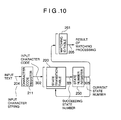
- Fig. 10 shows in a schematic block diagram a first embodiment of the character string matching (or collating) circuit incarnating the concept or principle of the present invention.
- the instant embodiment it is intended to realize a character string matching and retrieving system in a compact structure by implementing the matching ID table mentioned hereinbefore in conjunction with the prior art system such that the capacity of the memory therefor can be reduced to a possible minimum, for thereby realizing the caharacter string matching/retrieving system in a reduced size.
- the character string matching circuit or system is composed of a character code register 211 to which an input text 204 to be subjected to the retrieval is inputted on a character-by-character basis, a state transition table 220 designed for storing an input character code 302 outputted from the character code register 211 together with a succeeding state number indicated at 303 corresponding to a current state number indicated at 305, a state number register 250 for holding the succeeding state number 303 outputted from the abovementioned state transition table 220 as the current state number 305, and a matching ID table 261 for storing an identifier of a search term (i.e. term designated or specified for search or retrieval) in correspondence to the current state number 305 outputted from the state number register 250 as the result of the matching processing.
- a search term i.e. term designated or specified for search or retrieval
- the state number 0 (zero) is placed in the state number register 250, which number is regarded as the current state number 305, as mentioned above.
- the matching operation begins, starting from the inputting of the input text 204 to the character code register 211 on a character-by-character basis.
- the state transition table 220 is accessed by using as the addresss the character code 302 outputted from the character code register 211 and the current state number information 305 outputted from the state number register 250, whereby the succeeding state number 303 is outputted from the state transition table 220 and is held in the state number register 250 as the renewed or updated current state number 305.
- the matching ID table 261 is accessed by using as the address the current state number 305 outputted from the state number register 250, whereby the identification number or identifier of the search term is outputted from the matching ID table 261 as the result of the matching processing, as indicated at 205.
- Fig. 11 is a diagram showing in concrete a configuration of an automaton for realizing the character string matching operation.
- the matching ID table is so structured as to be accessed with the entry including the current state number and the state number of the destination state to which state transition occurs upon appearance of the trailing character of the search term.
- a transition destination state is newly created to which the state transition is made upon appearance of the trailing character constituting the last one of the search term or character string.
- the automaton shown in Fig. 11 is designed to make matching, for example, of "DOG” and "CAT" as with the case of the automaton shown in Fig. 4, wherein the matched result of "DOG” is outputted to the state 3 corresponding to the transition destination state to which transition is to be made upon appearance of "G", the trailing character of "DOG”, while the matched result of "CAT” is outputted to the state 6 representing the destination state to which transition is to be made upon occurrence of the trailing character "T” of the character string "CAT".
- the state indicated as enclosed by double circles such as the states 3 and 6 represents the state from which the matched result (i.e. the result of matching processing) is to be outputted.
- the matched term identifiers of the search terms are stored in the matching ID table in correspondence to the identification numbers of the states to which the matched results are outputted.
- the automaton now under consideration begins the state transition, starting from the state 0 (zero).
- state transition occurs to the state 1 (one), while the input character of "C” causes the automaton to transit to the state 4.
- appearance of the input character "O” in the state 1 brings about the state transition to the state 2
- the input character “D” brings about the state transition to the state 1 with the input character “C” making the automaton transit to the state 4.
- state transition occurs to the state 3 shown as enclosed by double circles, whereupon the matched term identifier of "DOG” is outputted from the matching ID table 261 as the result of matching processing.
- Fig. 12 shows a concrete example of the state transition table 220 used in the instant embodiment
- Fig. 13 shows an examplary structure of the matching ID table 261.
- the automaton for retrieving "DOG” and "CAT” as shown in Fig. 11 as well as the matched term identifiers for the search terms to be outputted when matching for "DOG” and "CAT" have been performed.
- the state transition table 220 shown in Fig. 12 is so configured as to be addressed with the input character code 302 and the current state number 305. Assuming, for example, that the current state number 305 is 1 (one) with the input character code 302 being "O", the state number of 2 which corresponds to 1 (one) and "O" is outputted as the succeeding state number as indicated at 303.
- the matching ID table 261 shown in Fig. 13 is so implemented as to be addressed with the current state number 305.
- the numerical value of the current state number 305 is 3 (indicating that "DOG" has been detected)
- the corresponding matched term identifier of the search term having a value of 1 is outputted as the result of the matching processing.
- the matched term identifier having a value of 0 (zero) indicates that the matching could not been been found.
- the matching ID table 261 of the character string matching circuit In contrast to the fact that the matching ID table 261 of the prior art character matching system requires a number of slots corresponding to a product of "maximum state number" and "the number of different types of character codes", the matching ID table 261 of the character string matching circuit according to the instant embodiment requires no more than a number of slots corresponding to the maximum or greatest state number, which in turn means that a memory of a small capacity is sufficient for realizing the matching ID table 261 and that the character string matching circuit or system can be realized in a reduced size.
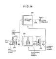
- Fig. 14 is a functional block diagram showing a character string matching circuit according to a second embodiment of the invention.
- the second embodiment of the character string matching circuit it is intended to carry out the matching of search terms without omission even upon occurrence of the multiple matching discussed previously.
- the character string matching circuit is composed of a character code register 211 to which an input text 204 to be subjected to the retrieval is inputted on a character-by-character basis, a state transition table 220 configured for storing the input character code 302 outputted from the character code register 211 and a succeeding state (ID) number 303 corresponding to a current state number 305, a state number register 250 for holding the succeeding state number 303 outputted from the abovementioned state transition table 220 as the current state number 305, and a matching ID table 262 for storing identifiers of search terms in correspondence to the input character codes 302 outputted from the state number register 250 and the current state number 305 as the result of the matching processing.
- the matching ID table is destined to store the matched term identifiers of the search terms.
- arrangement is made such that the identifier of the search term to be subjected to the matching is represented by one bit information so that a plurality of the search term identifiers can be stored in one slot of the matching ID table.
- the bit n of a matched term identifier storage area (slot) and a matching flag for n-th search term, it is possible to output simultaneously the results of matching for a plurality of search terms. In this manner, even upon occurrence of the multiple matching, the matched term identifiers for the relevant search terms can simultaneously be outputted as the bit information without any omission.
- the state number 0 (zero) is set at the state number register 250 and is regarded as representing the current state number 305.
- the matching operation begins, starrting from the inputting of the input text 204 to the character code register 211 on a character-by-character basis.
- the state transition table 220 is accessed with the character code 302 outputted from the character code register 211 and the current state number 305 outputted from the state number register 250, whereby the succeeding state number 303 is outputted from the state transition table 220 to be subsequently held in the state number register 250 as the renewed current state number 305.
- the matching ID table 262 is accessed by using as the address the current state number 305 outputted from the state number register 250 and the character code 302, whereby the matched term identifier of the search term is outputted from the matching ID table 262 as the result of the matching processing, as indicated at 205.
- the character string matching operation can be realized.
- the matching ID table 262 is structured to store the search term identifcation information as one bit information and allow simultaneous matching for a plurality of search terms, as will be elucidated below, in contrast to the prior art system in which the matching ID table is arranged to store the matched term identifier of the serach term. More specifically, Fig.
- the matching ID table 262 is designed to store as the bit information the matched term identifiers of the search terms for performing matching processing for "DOG” and "HOTDOG", as described above by reference to Fig. 7.
- a numerical value of "3" stored in the slot 500 corresponding to the current state number of 7 and the input character G indicates the multiple matching processing. In other words, it is indicated that matching processing has been performed for both the first search term "DOG” and the second search term "HOTDOG".
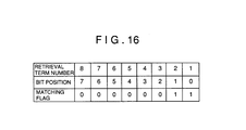
- Fig. 16 shows a structure of a multiple matching flag stored in the slot 500 of the matching ID table 262.
- Each of the matching flags corresponds to a search term in such a manner that a first search term is allocated with a 0-bit position, a second one is allocated with a first bit position and so forth.
- bit width of the slot of the matching ID table 262 has to be set in accordance with the number of the search term.
- the capacity of the matching ID table 262 will be in proportion to the number of the search terms.
- matching output can be obtained for eight search terms.
- Fig. 17 is a functional block diagram showing a third embodiment of the character string matching circuit according to the invention.
- the problem of possible omission of matching in the case of the multiple matching can certainly be solved.
- the capacity of the matching ID table increases in proportion to the number of the search terms.
- the character string matching circuit includes a character code register 211 for inputting an input text 204 which is subjected to retrieval on a per character basis, a state transition table 220 for storing an input character code 302 outputted from the character code register 211 and a succeeding state number 303 corresponding to a current state number 305, a state number register 250 for holding as the current state number 305 the succeeding state number 303 outputted from the state transition table 220, a matching ID table 263 for storing as the matching result the matched term identifiers of the search terms in correspondence to the current state number 305 outputted from the state number register 250, a multiple matching processing circuit 280 for outputting as the matching processing result the matched term identifiers of the search terms having the multiple matching relation from the matching ID table 263, and a multiple matching table 270 for storing information for the multiple matching relations.
- the state number 0 is placed in the state number register 250, which number is held as the current state number 305, as mentioned previously.
- the matching operation begins, starting from the inputting of the input text 204 to the character code register 211 on a character-by-character basis.
- the state transition table 220 is accessed by using as the address the character code 302 outputted from the character code register 211 and the current state number 305 outputted from the state number register 250, whereby the succeeding state number 303 is outputted from the state transition table 220, which is then to be held in the state number register 250 as the updated current state number 305.
- the matching ID table 263 is accessed by using as the address the current state number 305 outputted from the state number register 250, whereby the matched term identifier is outputted to the multiple matching processing circuit 280.
- the multiple matching processing circuit 280 makes decision on the basis of the matched term identifier inputted thereto as to whether the multiple matching is to be performed by referring to the multiple matching table 270. When the answer of this decision is affirmative (Yes), the matched term identifiers of the search terms which are in multiple matching relation are outputted as the matching result 205. In this way, there are stored in the multiple matching table 270 the matched term identifiers of the search terms which are to undergo the multiple matching in correspondence to the identifiers of the search terms.
- the matching processing for the input character strings can be carried out.
- the matching ID table 263 is designed to store the identifier information of the search terms to undergo the multiple matching for indicating simultaneously the matchings for a plurality of search terms, in contrast to the prior art system in which the matching ID table is designed to store the term identifier for the simple matching.
- the automaton shown in Fig. 7 is for the matching of "DOG” and "HOTDOG”. In the following description directed to the multiple matching, it is again assumed that the input character string "HOTDOG" is inputted.
- the input character of "O” in the state 3 brings about state transition to the state 4.
- the input character "T” in the state 4 causes the automaton to go to the state 5, being followed by the transition to the state 6 from the state 5 in response to the input of the character code "D".
- the input of the character code "O” in the state 6 causes the automaton to transit to the state 7. Since the input of the character "G” in the state 7 indicates the state transition for outputting the matching result, the matched term identifier for the search term corresponding to the matching result of "HOTDOG" is outputted from the matching ID table 263, and at the same time the automaton regains the state 0.
- the matching operation in general of the character string matching circuit according to the instant embodiment will be understood from the above. Now, description will be directed to an exemplary structure of the matching ID table 263 by reference to Fig. 18. As mentioned previously, the matching ID table 263 is designed to store the identifier information of the search terms for performing multiple matching for "DOG” and "HOTDOG", as described above by reference to Fig. 7.
- an identifier "100" stored in the slot 500 corresponding to the current state number of 7 and the input character G indicates the multiple matching of "DOG” and "HOTDOG".
- allocating the identification code greater than "100” to the term identifier for the multiple matching while allocating the identification codes in a range of "1" to "100” to the term identifier for the simple matching such as the identification code of "1" corresponding to the state number of 2 and the input character "G", it is possible to discriminatively identify the multiple matching from the other matching such as the simple matching.
- the multiple matching processing circuit 280 is additionally equipped with the multiple matching table 270 for storing a group of matched term identifiers of the search terms having the multiple matching relation in the slot which can be accessed by the matched term identifier.
- the matching ID table 270 stores a group of codes in two fields for the matched term identifiers and next data addresses, which fields can be accessed by using as address the matched term identifier.
- the matched term identifier field There are stored in the matched term identifier field the matched term identifiers of the search terms to undergo the multiple matching, which field is continued on the next data address field where the addresses to be next referred are stored.
- the multiple matching table 270 shown in this figure corresponds to the automaton shown in Fig. 7.
- a numerical value of "100" stored at the entry designated by the current state number of 7 and the input character "G" indicates that what is concerned is the multiple matching.
- the multiple matching processing circuit 280 first outputs "1" which is the matched term identifier of "DOG" stored at the address "100" of the multiple matching table 270 corresponding to the matched term identifier "100".
- the matched term identifier inputted to the multiple matching processing circuit 280 is a matched term identifier on the order of "100"
- the matched term identifier is represented by a numerical value smaller than "100”
- the corresponding matched term identifier is outputted from the multiple matching table 270. Subsequently, the next data address is referred to, whereon the matched term identifier bearing the multiple matching relation at that address is outputted as the result of matching. Similarly, a next data address succeeding to the abovementioned data address is referred to for outputting the next matched term identifier of the search term the multiple matching relation.
- the next data address contains the termination code (-1), it is then decided that there exists no more the search term having the multiple matching relation. Accordingly, the result of matching is no more outputted. It should be noted that by using "-1" " as the termination code, the matched term identifier of the search term can be discriminated from the termination code.
- the multiple matching can be realized while solving successfully the problem that the memory capacity of the matching ID table 263 will otherwise increase in proportion to the number of the search terms.
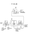
- Fig. 20 shows in a schematic block diagram a fourth embodiment of the character string matching system incarnating the principle of the present invention.
- the instant embodiment of the character string matching circuit is intended to solve the problem of the multiple matching which can not be realized with the first embodiment while implementing the matching ID table with a reduced memory capacity to thereby provide a compact structure of the character string retrieving system.
- the character string matching circuit is composed of a character code register 211 to which an input text 204 to be subjected to the retrieval or searchis inputted on a character-by-character basis, a state transition table 220 adapted to store an input character code 302 outputted from the character code register 211 and a succeeding state number 303 corresponding to a current state number 305, a state number register 250 for holding the succeeding state number 303 outputted from the abovementioned state transition table 220 as the current state number 305, and a matching ID table 264 for storing matched term identifier in correspondence with the current state number 305 outputted from the state number register 250 as the result of matching processing.
- the matching ID table is destined to store the identification numbers of the search terms.
- arrangement is made such that the matching information of the search term is represented by the one bit information so that a plurality of the matched term identifiers can be stored in one slot of the matching ID table 264.
- the matching information of the search term is represented by the one bit information so that a plurality of the matched term identifiers can be stored in one slot of the matching ID table 264.
- the state number 0 (zero) is set at the state number register 250, which is held as the current state number 305.
- the matching operation starts from the inputting of the input text 204 to the character code register 211 on a character-by-character basis.
- the state transition table 220 is accessed by using as the address the character code 302 outputted from the character code register 211 and the current state number 305 outputted from the state number register 250, whereby the succeeding state number 303 is outputted from the state transition table 220 to be held in the state number register 250 as the updated current state number 305.
- the matching ID table 264 is accessed by using as the address the current state number 305 outputted from the state number register 250, whereby the matched term identifier is outputted from the matching ID table 264 as the result of matching, as indicated at 205.
- the following description is directed to operation of the character string matching circuit according to the instant embodiment on the assumption that an automaton shown in Fig. 21 is used which is of the utterly same structure as that used in the first embodiment of the invention described hereinbefore. Accordingly, the state transition table 220 is also of the same structure as that employed in the first embodiment. It is however to be noted that the matching ID table 264 is designed to store the matched term identifier as one bit information to thereby allow a plurality of search terms to be simultaneously matched, as will be described below, in contrast to the matching ID table of the first embodiment which is arranged to store the matched term identifier in the form of the code.
- Fig. 21 there is shown an automaton for performing the matching on the terms "DOG” and "HOTDOG”.
- HOTDOG is inputted as an input character string.
- the input character of "O” in the state 4 brings about state transition to the state 5.
- the input character "T” in the state 5 causes the automaton to make transition to the state 6, being followed by the transition to the state 7 from the state 6 in response to the input of the character "D".
- the input of the character "O” in the state 7 causes the automaton to transit to the state 8.
- the input of the character "G” in the state 8 brings about the state transition to the state 9 indicated as enclosed by double circles, whereon the matched term identifier corresponding to the matching result of the search term "HOTDOG" is outputted from the matching ID table 264 as the bit information.
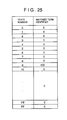
- the matching operation in general of the character string matching circuit according to the fourth embodiment of the invention will be understood from the above. Now, description will be directed to exemplary structures of the state transition table 220 shown in Fig. 22 and the matching ID table shown in Fig. 23, respectively. As previously mentioned, the tables used in the instant embodiment are adapted to store the automaton for performing the matching on the terms "DOG” and "HOTDOG” described above by reference to Fig. 21 and the matched term identifiers as the bit information, respectively.
- the state transition table 220 shown in Fig. 22 is so configured as to be addressed with the input character code 302 and the current state number 305. Assuming, for example, that the current state number 305 is 1 (one) with the input character code 302 being "O", the state number of 2 which corresponds to the combination of 1 and "O" is outputted as the succeeding state number 303.
- a numerical value of 3 stored in the slot 501 corresponding to the current state number of 9 indicates the multiple matching. In other words, it is indicated that matching has been performed for both the first search term "DOG" and the second search term "HOTDOG".
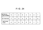
- Fig. 24 shows a structure of multiple matching flags stored in the slot 501 of the matching ID table 264.
- Each of the matching flags corresponds to a search term to be matched in such a manner that a first search term is allocated with a 0-bit position, a second one is allocated with a first bit position and so forth.
- bit width of the slot of the matching ID table 264 has to be so set as to conform with the number of the terms to be retrieved.
- the capacity of the matching ID table 264 is in proportion to the number of the search terms.
- matching result can be outputted for eight terms specified or designated for the retrieval.
- a fifth embodiment of the character string matching system will be described.
- the instant embodiment it is contemplated to solve the problem that the memory capacity increases in proportion to the number of the serch terms to be retrieved, as described just above in conjunction with the fourth embodiment.
- the character string matching circuit includes a character code register 211 for inputting an input text 204 to be subjected to retrieval on a character-by-character basis, a state transition table 220 for storing the input character code outputted from the character code register 211 and a succeeding state number 303 corresponding to a current state number 305, a state number register 250 for holding as the current state number 305 the succeeding state number 303 outputted from the state transition table 220, a matching ID table 265 for storing as the result of matching the matched term identifier in correspondence to the current state number 305 outputted from the state number register 250, a multiple matching processing circuit 280 for outputting as the result of the matching the matched term identifiers of the search terms which have the multiple matching relation from the identifiers stored in the matching ID table 265, and a multiple matching table 270 for storing information of the multiple matching relation of the search terms.
- the state number 0 is placed in the state number register 250, which number is held as the current state number 305.
- the matching operation begins, starting from the inputting of an input text 204 to the character code register 211 on a character-by-character basis.
- the state transition table 220 is accessed by using as the address information the character code 302 outputted from the character code register 211 and the current state number 305 outputted from the state number register 250, whereby the succeeding state number 303 is outputted from the state transition table 220 to be subsequently held in the state number register 250 as the renewed current state number 305.
- the matching ID table 263 is accessed with the current state number 305 outputted from the state number register 250, whereby the corresponding identifier is outputted to the multiple matching processing circuit 280.
- the multiple matching processing circuit 280 makes decision on the basis of the matched term identifier inputted thereto as to whether the multiple matching is to be performed by referring to the multiple matching table 270. If it is the multiple matching indicating identifier, the identifiers of the terms which are in the multiple matching relation are outputted. In this way, there are stored in the multiple matching table 270 the identifiers of the search terms to undergo the multiple matching in correspondence to the matched term identifiers.
- the character string matching can be carried out.
- the matching ID table 265 is designed to store the identifier information of the search terms for the multiple matching and indicate the matching for a plurality of the search terms simultaneously, in contrast to the matching ID table of the first embodiment which is designed to store the identifier of the term to undergo the single matching.
- the automaton shown in Fig. 21 is for the matching of "DOG” and "HOTDOG”. In the following description directed to the multiple matching, it is again assumed that the input character string is the term "HOTDOG".
- the input character of "O” in the state 3 brings about state transition to the state 5.
- the input character "T” in the state 5 causes the automaton to make transition to the state 6, being followed by the transition to the state 7 from the state 6 in response to the input of the character "D".
- the input of the character "O” in the state 7 causes the automaton to transit to the state 8.
- the input of the character "G” in the state 8 results in the state transition to the state 9 in which the matched term identifier for the search term corresponding to the matching result of "HOTDOG" is outputted from the matching ID table 265.
- the matching ID table 265 is designed to store the search term identifier information for performing matching for the terms "DOG” and "HOTDOG", as described hereinbefore by reference to Fig. 21.
- an identifier "100" stored in the slot corresponding to the current state number of 7 and the input character "G” indicates the multiple matching of the search terms "DOG” and "HOTDOG".
- the identification codes of values greater than "100", inclusive, to the term identifiers indicating the multiple matchings while allocating the identification codes in a range of "1" " to "99” to the other matchings as with the case of the term identifier for the single matching such as the identification code "1" " corresponding to the state number of 2 and the input character "G"
- the multiple matching can discriminatively be identified from the other type matching.
- the multiple matching processing circuit 280 is provided with a multiple matching table 270 which stores a group of matched term identifiers for the search terms having the multiple matching relation in a slot which can be accessed with the matched term identifier.
- the multiple matching table 263 stores code groups of the matched term identifiers and the next data addresses in two fields, respectively, which can be accessed by using as address the matched term identifier.
- the multiple matching table 270 employed in the instant embodiment may be of the same structure as that of the third embodiment described hereinbefore by reference to Fig. 19. By referring to this figure, operation of the multiple matching processing circuit 280 according to the instant embodiment will be described in detail.
- the multiple matching table 270 shown in Fig. 19 corresponds to the state transition diagram shown in Fig. 21.
- the matching ID table 265 a numerical value of "100" stored at the entry designated by the current state number of 9 and the input character "G" indicates that the multiple matching is of concern.
- the multiple matching processing circuit 280 When the code value "100" representing the matched term identifiers of the search terms is outputted from the matching ID table 265, the multiple matching processing circuit 280 outputs "1" which is the matched term identifier of "DOG" stored at the address "100" of the multiple matching table 270 in correspondence to the matched term identifier "100". In this case, since the next data address is "200", the matched term identifier "2" for the term "HOTDOG” stored at the address "200” is also outputted. Then, the next data address becomes “-1 ". Accordingly, any succeeding matched term identifier can no more be outputted.
- the matched term identifier inputted to the multiple matching processing circuit 280 is the identifier on the order of "100"
- the matched term identifier is smaller than "100”
- the corresponding matched term identifiers are outputted from the multiple matching table 270. Subsequently, the next data address is referred to, and the matched term identifier for the multiple matching relation is outputted as the result of matching (or collation). Similarly, a next data address succeeding to the abovementioned next data address is referred to for outputting the next matched term identifier of a search term (i.e. term designated or specified for retrieval) having the multiple matching relation.
- the next data address contains the termination code (-1), it is then decided that there exists no more the search term having the multiple matching relation. Accordingly, result of the matching is not outputted any more. It should be noted that by using "-1" as the termination code, the matched term identifier of any search term can be discriminated from the termination code.
- the multiple matching can be realized while solving successfully the problem that the memory capacity of the matching ID table 265 will otherwise increase in proportion to the number of the terms to be matched and retrieved.
- a sixth embodiment of the character string matching system is also arranged such that the terms to be retrieved can be matched without any omission notwithstanding of occurrence of the multiple matching.
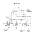
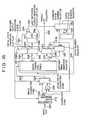
- Fig. 26 shows a circuit configuration of the character string matching system according to the sixth embodiment.
- the system includes a character code register 212, a state transition table 220, a matching ID table 266 and a state register 250.
- an automaton corresponding to search terms i.e. terms to undergo matching and retrieval
- the state transition table 220 while there is stored in the matching ID table a matching identifier corresponding to a state number and a character code together with a multiple matching flag which will be described hereinafter.
- the state number 0 representing the initial state number of the automaton is placed in the state number register 250, which is held thereby as the current state number at that time point.
- the matching operation begins, starting the inputting of an input text 204 to the character code register 212 on a character-by-character basis.
- the state transition table 220 is accessed with the character code 302 outputted from the character code register 212 and the current state number 305 outputted from the state number register 250, whereby a succeeding or next state number 303 representing the identification number of the state to which the next state transition is to take place is read out from the state transition table 220.
- the succeeding state number 303 is held in the state number register 250 as the renewed current state number 305.
- the matching ID table 266 is also accessed by using as the address the current state number 305 outputted from the state number register 250 and the input character code 302, as a result of which there are read out from the matching ID table 266 the matching identifier 205 of the retrieval term and the multiple matching flag 308.
- the matching identifier of the search term is assigned with a value other than "0" (zero). Accordingly, when the matching identifier as read out has other value than "0" (zero), the identifier is regarded as that of the result of matching. If otherwise, the identifier is not regarded as that of the matching result.
- the state transition table 220 is accessed with the character code 302 and the current state number 305, whereby the succeeding state number 303 is outputted.
- This succeeding state number 303 is held in the state number register 250 as the renewed current state number 305.
- the matching ID table 266 is also accessed.
- the multiple matching flag 308 outputted from the matching ID table 226 is "1"
- reading of a new character from the input text into the character code register 212 is suspended, and the matching ID table 266 is accessed by using as the address the renewed current state number 305 and the character code 302 which is currently held in the character code register 212, whereby there are read out from the matching ID table 266 the matching identifiers for the search term bearing the multiple matching relation, which identifiers are stored in the matching ID table 266 in correspondence to the succeeding state number 303.
- the character string matching operation is carried out by repeating the abovementioned operations in accordance with the contents of the multiple matching flag 308.
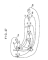
- the state 8 indicated as enclosed by a quadrangle represents the matching output dedicated state. Further, in this state 8, character code is no more fetched from the input text with the comparison operation being carried out with the character code fetched in the state 7.
- Transition indicating arrows 404 and 406 affixed with slash "/" indicate that upon occurrence of transitions indicated by these arrows, the corresponding matching identifiers are outputted from the matching ID table 266. More specifically, upon occurrence of the transition indicated by the arrow 404, the matching identifier for "DOG” is outputted from the matching ID table 266, while upon occurrence of the transition indicated by the arrow 406, the matching identifier for "HOTDOG" is outputted from the matching ID table 266.
- the automaton begins the state transition, starting from the initial state 0 (zero).
- the input character of "0" in the state 3 brings about state transition to the state 4.
- the input character "T” in the state 4 causes the automaton to make transition to the state 5, being followed by the transition to the state 6 from the state 5 in response to the input of the character "D".
- the input of the character “O” in the state 6 causes the automaton to transit to the state 7.
- the input of the character “G” in the state 7 brings about the state transition to the state 8, and at the same time, the matching identifier for the matching result of "HOTDOG” is outputted from the matching ID table 266.
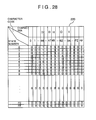
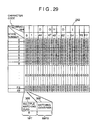
- Figs. 28 and 29 show exemplary structures of the state transition table 220 and the matching ID table 266, respectively, which correspond to the automaton described above. It should be noted that JIS code is used as the character code.
- the state transition table 220 shown in Fig. 28 is addressed with the input character code 302 and the current state number 305 of the automaton, whereby the succeeding state number is read out.
- the matching ID table 266 shown in Fig. 29 Stored in the matching ID table 266 shown in Fig. 29 are the matching identifier 205 for a retrieval term indicating that the retrieval term has been matched and the multiple matching flag 308 indicating whether or not the state indicated by the succeeding state number 303 is the matching output dedicated state.
- the multiple matching flag is stored in a slot corresponding to the state 7 and the character code G. More specifically, the multiple matching flag of "1" and the matching identifier of "2" are placed in the slot corresponding to the state 7 and the character code "G".
- the character code register 212 makes transition to the succeeding state 8 while holding the character code "G", and at the same time the matching ID table outputs "2" as the matching identifier for the retrieval term and "1" as the multiple matching flag. Since the multiple matching flag is set to "1", the comparison processing is again performed for the character code "G” in the succeeding state 8, whereon "0" (zero) representing the next succeeding state is read out from the state transition table 220 while at the same time the matching identifier "1" " is read out from the matching ID table 266.
- the matching identifier of "1" for the multiple matching is outputted as the result of matching. Further, since the multiple matching flag 308 is "0" (zero), inputting of a character code is again started in the succeeding transition destination state 0 (zero), whereon the comparison processing is continued.
- the character string matching can be realized without any omission even upon occurrence of the multiple matching.
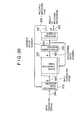
- Fig. 30 is a schematic block diagram showing the character string matching circuit according to the seventh embodiment of the invention.
- this character string matching circuit is composed of a character code register 212, a state transition table 220, a matching ID table 267 and a state number register 250.
- description will be directed to the normal comparison or matching operation in which no multiple matching occurs.
- the state transition table 220 is accessed with the character code 302 outputted from the character code register 212 and the current state number 305, whereby the succeeding state number 303 to which the next state transition is to take place is outputted from the state transition table 220 to be held in the state number register 250 as the renewed current state number 305.
- the matching ID table 267 is accessed by using as the address the current state number 305 outputted from the state number register 250, whereby the matching identifier 205 of the search term and the multiple matching flag 308 are outputted from the matching ID table 267.
- the matching identifier 205 as read out is "0" (zero), it is not regarded as identifying the matching result of the search term.
- the state transition table 220 is accessed with the character code 302 and the current state number 305, whereby the succeeding state number 303 is read out, which is then held in the state number register 250 as the renewed current state number 305.
- the matching ID table 266 is accessed with the current state number 305 stored in the state number register 250, as a result of which there are outputted the matching identifiers of the search terms and the multiple matching flag 308.
- the character code register 250 makes state transition while suspending again the inputting of the character code from the input text, to thereby read out the matching identifier of the next search term which has the multiple matching relation.
- the character string matching operation including the multiple matching can be realized, whereby the multiple matching identifiers of the search terms can be outputted without any omission.
- the matching identifier of a search term is placed in a slot of the matching ID table which is addressed with the current state number and the trailing character of the search term.
- the matching identifier is outputted when transition takes place in response to the trailing or last character of the search term.
- such automaton is employed in which a new state is created as the transition destination state for the trailing character of the search term. More specifically, the automaton is implemented such that when the current state transits to the state 3 which is the succeeding state for the trailing character "G" of "DOG", as shown in Fig. 31, the matching identifier of "DOG" is outputted.
- the state indicated as enclosed by double circles such as the state 3 and the state 10 represents the state from which the matching identifier is to be outputted.
- Fig. 31 the state indicated as enclosed by double quadrangles represents the matching output dedicated state.
- the state 9 no character code is inputted, and comparison is performed with the character code matched in the state 8.
- the state 3 and 10 the result of matching of "DOG” is stored, while in the state 9 the result of matching of "HOTDOG” is stored.
- the state of concern makes transition from the initial state 0 (zero) to the state 4.
- the input character "O” in the state 4 brings about transition to the state 5.
- the input character "T” in the state 5 causes state transition to the state 6 which then transits to the state 7 in response to the input character "D”.
- the state 7 then transits to the state 8 in response to the input character "O”.
- Inputting of "G” in the state 8 brings about state transition to the state 9 where the result of matching is to be stored.
- the matching identifier corresponding to the search term "HOTDOG" stored in the state 9 of the matching ID table 267 is read out.
- This state 9 is the matching output dedicated state and thus transits to the state 10 without fetching any further character code.
- the matching identifier corresponding to the retrieval term "DOG" is outputted from the matching ID table.
- Figs. 32 and 33 show, respectively, exemplary structures of the state transition table 220 for storing the automaton shown in Fig. 31 and the matching ID table 260.
- the state transition table 220 is so structured that it can be addressed with the input character code 302 and the current automaton state number 305 of concern.
- the matching ID table 267 stores therein the matching identifier indicating that the matching has been made for the search terms and the multiple matching flag 308 indicating whether or not the current state is the matching output dedicated state.
- the multiple matching flag of the slot corresponding to the multiple matching state 9 is set to "1" with the matching identifier being set to "2".
- any additional character code is inhibited from being inputted to the character code register 212 since the multiple matching flag is "1" " in the state 9. Accordingly, state transition to the succeeding state 10 is made with the character code "G" inputted immediately before being held in the character code register 212.
- the matching ID table can be realized in a small size or reduced capacity. Besides, the search terms can be matched without omission even upon occurrence of the multiple matching.
- the state indicated as enclosed by double quadrangles represents the matching output dedicated state. In this state, any character can not be fetched from the input text but only the outputting of the matching result is performed.
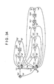
- Fig. 34 there are illustrated representatively three matching output dedicated states 310, 311 and 312, where matched term identifiers for "DOG” and "HOTDOG” are stored, respectively. Accordingly, upon transition made to any one of these states, the corresponding matched term identifier is outputted, indicating that the matching has been done on the corresponding search term.
- a matching output dedicated state flag which is adapted to be affixed to the transition information.
- the matching output dedicated state flags indicating the transition from the state 2 to the matching output dedicated state 310, transition from the state 2 to the matching output dedicated state 311 and the transition from the matching output dedicated state 311 to the matching output dedicated state 312, respectively, are each set to "1".
- the matching output dedicated state flags indicating other transitions than those mentioned above are each set to "0".
- state transition of concern takes place from the initial state 0 to the state 4.
- inputting of the succeeding character "O” brings about state transition from the state 4 to the state 5.
- the state transition occurs from the state 5 to the state 6, to the state 7 and then to the state 8.
- the matching output dedicated state flag assumes a value of 0 (zero) because of the normal state transitions.
- the state transition occurs to the state 8 indicated as enclosed by double quadrangles and representing the matching output dedicated state 311 where the result of matching is to be stored.
- the matching output dedicated state 311 the matched term identifier of "DOG" stored in this state is outputted, indicating that the matching has been performed for the term "DOG”. Further, in the matching output dedicated state 311, no character code is fetched but the character "G" fetched immediately before is held.
- state transition occurs to the matching output dedicated state 312 having the state number 8.
- the matching output dedicated state flag associated with this state transition is set to 1.
- the matching output dedicated state 312 the matched term identifier of "HOTDOG” stored in this state is outputted, indicating that matching of "HOTDOG” has been made.
- no character code is fetched but transition is made to the state 9 while holding the character "G". Since the state 9 is the normal state, the matching output dedicated state flag is set to "0" (zero). Accordingly, in this state 9, the succeeding character code is fetched from the input text to undergo the normal comparison operation.
- Fig. 35 is a block diagram showing a configuration of the character string matching circuit which can be used for implementing the instant (eighth) embodiment of the invention.
- the character string matching system includes a character code register 212, an adder 230, a state transition table 221, an initial state number register 252, selectors 291 and 293, a state number register 251, a matched term identifier register 253, a matching output dedicated state flip-flop 255, an initial state transition flip-flop 256, a last matching output dedicated state flip-flop 257, inverters 258 and 269 and an AND gate 259.
- the character code register 212 is loaded with a character code corresponding to one character of the input text, when a matching output dedicated state signal 309 described hereinafter is "0" (zero), wherein the output of the character code register 212 is supplied to the character code selector 291 and the adder 230.
- the selector 291 selects an X-port, whereby the character code placed in the character code register 212 is outputted, as it is, to the state transition table 221 as a column address thereof.
- the selector 291 selects a Y-port, whereby the output of the adder 230 (i.e. a value resulting from addition of the character code 302 and an offset 310L) is supplied to the state transition table 221 as a column address thereof.
- the state transition table 221 is addressed with the character code serving as the column address and the current state number 305 serving as a row address, as a result of which there are outputted from an addressed slot of the state transition table 221 an initial state transition flag 320, a matching output dedicated state flag 308 and a succeeding state number 310 stored in that slot.
- the initial state transition flag 320 serves for indicating whether state transition of concern is to the initial state or not. More specifically, when this flag is "1" (one), it indicates the state transition to the initial state. In the case of the illustrated example, this kind state transition takes place in response to the input of a character code other than "D", "O” and "H” in the state 1. In that case, the initial state transition flag 320 of the corresponding slot of the state transition table 221 is set to "1" (one). On the other hand, the initial state transition flag of "0" (zero) indicates the state transition to the other state than the initial state. In the illustrated case, this kind state transition takes place in response to the appearance of "D", "O” and "H” in the initial state 1. At this time, the initial state transition flag 320 of the corresponding slot of the state transition table 221 is set to "0" (zero).
- the initial state transition flag 320 outputted from the state transition table 221 is loaded in the initial state transition flip-flop 256 to be subsequently outputted to the AND gate 259 as the initial state transition information 321.
- the matching output dedicated state flag 309 serves to indicate whether or not the transition destined state is the matching output dedicated state indicated as enclosed by double quadrangles in Fig. 34.
- the flag 308 is "1" (one) it is indicated that the state to which the succeeding transition is to take place is the matching output dedicated state.
- the transitions to the matching output dedicated states include state transition from the state 2 to the matching output dedicated state 310, transition from the state 8 to the matching output dedicated state 311 and the transition from the matching output dedicated state 311 to the matching output dedicated state 312.
- the matching output dedicated state flag is set to "1" (one).
- the matching output dedicated state flag of "0" (zero) indicates that the transition destined state is the normal state.
- these normal state transitions include the transition from the state 1 to the state 2, transition from the matching output dedicated state 310 to the state 3, and the transition from the matching output dedicated state 312 to the state 9.
- the corresponding matching output dedicated state flag is set to "0" (zero).
- the matching output dedicated state flag 308 outputted from the state transition table 221 is then placed in the matching output dedicated state flip-flop 255 to be subsequently supplied as the aforementioned matching output dedicated state signal 309 to the character code register 212, the selector 291, the last matching output dedicated state flip-flop 257, the state number register 251 and the matching identifier register 253 via the inverter 269, respectively.
- the matching identifier register 253 fetches therein a succeeding state number 310 outputted from the state transition table 221, whereon the matched term identifier composed of four more significant bits of the succeeding state number 310 is outputted as the result of matching, while the offset 310L which is composed of the four less significant bits of the succeeding state number 310, as described hereinafter, is outputted to the adder 230 to be thereby added with the character code 302.
- the output of the adder 230 is applied to the Y-port of the selector 291.
- the offset 310L is utilized to determine an offset involved in the transition to the succeeding transition destined state or the matching output dedicated state as well as an address of the slot of the state transition table 221 in which the matched term identifier is stored.
- the offset involved in the transition from the state 2 to the matching output dedicated state 310 can be determined by subtracting the slot address of the state transition table 221 at which the abovementioned transition is stored from the slot address of the state transition table 221 at which the transition from the matching output dedicated state 310 to the state 3 is stored.
- the matching output dedicated state signal 309 is "0" (zero), i.e. when the state transition destined state is the normal state, the matching identifier register 253 is inhibited from fetching the succeeding state number 310 outputted from the state transition table 221.
- the state number register 251 fetches therein the succeeding state number 310 outputted from the state transition table 221 when the matching output dedicated state signal 309 is "0" (zero), while the state number register 251 is inhibited from fetching the succeeding state number 310 when the matching output dedicated state signal 309 is "1" (one).
- the last succeeding state number already placed in the state number register 251 is held to be outputted to a W-port of the selector 293.
- the last matching output dedicated state flip-flop 257 fetches therein the matching output dedicated state signal 309 used in the preceding state transition, which signal 309 is then supplied to the AND gate 259 via the inverter 258.
- the last matching output dedicated state signal 323 of "1" (one) indicates that the current state is the matching output dedicated state while the signal 323 of "0" (zero) indicates that the current state is the normal state.
- the AND gate 259 When the AND gate 259 is applied with the last matching output dedicated state signal 323 of "0" (zero) via the inverter 258 together with the initial state transition signal 321 of "1", i.e. when the state transition takes place from the normal state to the initial state, the AND gate 259 outputs a signal of "1" which is then supplied to the selector 293 as a current state number select signal. At this time, a V-port of the selector 293 is selected, whereby the initial state number stored in the initial state number register 252 is outputted as the current state number 305, i.e. as the row address of the state transition table 221.
- the initial state number register 252 is set to "0" (zero) since the initial state number is "0" (zero). Because no multiple matching can take place in the initial state, the matching output dedicated state flip-flop 255 and the last matching output dedicated state flip-flop 257 are each loaded with “0" as the respective initial value. Accordingly, the matching output dedicated state signal 309 and the last matching output dedicated state signal 323 assume “0" (zero). Further, the initial state transition flip-flop 256 is placed with "1" as the initial state signal 321 to indicate that the state transition is started from the initial state.
- the comparing or collating operation is started by inputting an input text 204 to the character code register 212 on a character-by-character basis.
- the character code 302 outputted from the character code register 212 is sent to the selector 291.
- the selector 291 the X-port is selected because the matching output dedicated state signal 309 is "0", indicating that the current state is not the matching output dedicated state. Consequently, the character code 302 is sent out to the state transition table 221 as the column address.
- the current state number select signal 322 is "0" (zero) because the last matching output dedicated state signal 323 is "0" and because the initial state signal 321 is "1".
- the current state number selector 293 the V-port is selected, whereby the initial state number 0 (zero) is outputted as the current state number signal 305.
- the character code 302 and the initial state number 0 (zero) are supplied to the state transition table 221 as the column address and the row address, respectively.
- the matching output dedicated state flag 308 the initial state transition flag 320 and the succeeding state number signal 310.
- the matching output dedicated state signal 309 is placed in the last matching output dedicated state flip-flop 257 as the last matching output dedicated state signal 323. Subsequently, the matching output dedicated state flag 308 read out from the state transition table 221 is stored in the matching output dedicated state flip-flop 255 to be outputted therefrom as the matching output dedicated state signal 309. Further, the initial state transition flag 320 read out from the state transition table 21 is stored in the initial state transition flip-flop 256 to be outputted as the updated initial state signal 321.
- the matching output dedicated state signal 309 is "0", i.e. when the transition destined state is the normal state, the succeeding state number signal 310 is stored in the state number register 251 as an updated current state number.
- the current state number select signal 322 assumes "0", resulting in that the W-port is selected in the selector 293, whereby the content of the state number register 251 is outputted as the current state number signal 305.
- Such matching operation may be performed upon state transition from the state 0 (zero) to the state 1. Since the last matching output dedicated state flip-flop 257 is loaded with "0" (zero), the last matching output dedicated state signal 323 is “0". Accordingly, when the initial state signal 321 is "1", the current state number select signal 322 assumes "1" and the V-port is selected in the selector 293, whereby "0" stored in the initial state number register 252 is outputted to the state transition table 221 as the current state number 305.
- This kind matching operation is performed upon state transition to the state 0 from the state 1 in response to the input of other character code than "D", "O” or "H".
- the matching output dedicated state signal 309 is "1" i.e. when the transition destined state is the matching output dedicated state, the current state number 305 in the state number register 251 is not updated but the last (or outdated) succeeding state remains as being held.
- this kind of matching operation takes place upon occurrence of transition from the state 2 to the matching output dedicated state 310, transition from the state 8 to the matching output dedicated state 311 or the transition from the matching output dedicated state 311 to the matching output dedicated state 312.
- the matched term identifier register 253 there are stored in the matched term identifier register 253 the matched term identifier together with the offset 310L for reading out from the state transition table 221 the matched term identifier in the succeeding state or the matched term identifier in the matching output dedicated state and the offset stored in the corresponding slot.
- the matched term identifier as stored is outputted as the result of matching processing, as indicated at 205, while the offset 310L is supplied to the adder 230.
- the initial state signal 321 is "0".
- the W-port for the state number register 251 is selected. Accordingly, the succeeding state number held continuously in the state number register 251 is outputted as the row address of the state transition table 221.
- the matching output dedicated state signal 309 of "1" " is newly stored as the last matching output dedicated state signal 323 to be subsequently outputted to the AND gate 259 via the inverter 258.
- the matching output dedicated state signal 309 Since the matching output dedicated state signal 309 is "1", the character code register 212 is inhibited from fetching newly any character code, wherein the character code 302 already stored is outputted from the character code register 212 to the selector 291 and the adder 230. Since the matching output dedicated state signal 309 is "1", the Y-port is selected in the selector 291, whereon a sum of the offset 310L and the character code 302 is outputted from the adder 320 as the column address for the state transition table 221.
- the matching output dedicated state signal 309 is stored in the last matching output dedicated state flip-flop 257 as the last matching output dedicated state signal 323.
- the matching output dedicated state flag 308 and the initial state transition flag 320 as read out are stored in the matching output dedicated state flip-flop 255 and the initial state transition flip-flop 256, respectively, to be outputted as the updated matching output dedicated state signal 309 and the updated initial state signal 321, respectively.
- the matching output dedicated state signal 309 is "1" i.e. when the transition destined state continues to be the matching output dedicated state, the current state number value 305 in the state number register 251 is not updated but the last succeeding state number remains to be held.
- the matched term identifier register 253 is loaded with new term identifier and the offset 310L.
- the matched term identifier as stored is outputted as the matching proceesing result 205, while the offset 310L is sent to the adder 230.
- the initial state signal 321 still continues to be "0".
- the W-port is selected for allowing the output of the state number register 251 to be inputted. Consequently, the last succeeding state number stored in the state number register 251 continues to be outputted as the current state number signal 305 to be utilized as the row address in making access to the state transition table 221.
- Stored in the last matching output dedicated state flip-flop 257 is the matching output dedicated state signal 309 of "1" as the last matching output dedicated state signal 323, which is then supplied to the AND gate 259 via the inverter 258.
- the matching output dedicated state signal 309 Since the matching output dedicated state signal 309 is "1", the character code register 212 is inhibited from fetching a new character code. Consequently, the character code 302 already placed in the character code register 212 continues to be outputted therefrom to the selector 291 and the adder 230. Because the matching output dedicated state signal 309 is "1", the Y-port is selected in the selector 291, resulting in that a sum value of the offset 310L and the character code 302 is outputted as the column address for making access to the state transition table 221.
- the matched term identifier and the offset stored in the state transition tale 221 are read out with the same character code 302 and the current state number 305 being held in the character code register 212 and the state number register 251, respectively.
- the matching output dedicated state signal 309 is "0", i.e. when the transition destined state is the normal state, the succeeding state number 310 is stored in the state number register 251 as the updated or renewed current state number, while a new character code is fetched by the character code register 212, whereupon the state transition is made backwardly from the matching output dedicated state to the normal state.
- this kind of matching operation is performed upon transition from the matching output dedicated state 310 to the state 3 and transition from the matching output dedicated state 312 to the state 9.
- the transition from the normal state 2 to the matching output dedicated state 310 where the result of matching of "DOG” is stored and hence to the normal state 3 in the case of the example assumed above can be realized by performing only once the transition from the normal state to the matching output dedicated state and the transition from the matching output dedicated state to the normal state, respectively.
- the transition from the normal state 8 to the matching output dedicated state 312 where the matching result of "DOG” is stored and the matching output dedicated state 312 where the matching result of "HOTDOG” is stored and hence to the normal state 9 can be realized by performing only once the transition from the normal state to the matching output dedicated state, transition from the one matching output dedicated state to the other matching output dedicated state and the transition from the last mentioned matchingoutput dedicated state to the normal state, respectively.
- Fig. 36 shows concretely an exemplary structure of the state transition table 221 for storing the automaton shown in Fig. 34.
- the state transition table 221 is so structured as to be addressed with the character code serving as the column address and the current state number 305 serving as the row address, wherein the slot as addressed stores therein the initial state transition flag 320, the multiple matching (or collation) flag 308 and the succeeding state number information 310.
- the initial state transition flag 320 set to "1" indicates that the transition destined state is the initial state, while the transition destined state is other state than the initial state when the flag 320 is set to "0".
- the multiple matching flag 308 of "1" indicates that the transition destined state is the matching output dedicated state while indicating the normal state as the transition destined state, when it is "0".
- the succeeding state number information 310 indicates the number which identifies the state to which transition is to be made next, when the multiple matching flag 308 is "0".
- the slot is then of such a structure as indicated at 502 in Fig. 36.
- the succeeding state number 310 is constituted by the matched term identifier of four more significant bits and the offset of four less significant bits.
- the slot structure is such as indicated at 503 in Fig. 36. This offset is made use of in determining the slot address of the state transition table 221 at which the matched term identifier and the offset in the succeeding state or the matching output dedicated state are to be stored.
- the registers and the flip- flops are set to the respective states described below.
- the initial state number 0 (zero) is placed at the initial state number register 252.
- the initial state transition flip-flop is placed with "1" for starting the state transition, beginning with the initial state. Since the initial state can never become the matching output dedicated state, the multiple matching flip-flop 255 and the last multiple matching flip-flop 257 are each loaded with "0" (zero). As a result of this processing, the initial state number 0 is supplied to the state transition table 221 as the current state number 305.
- the state transition table 221 is accessed with the character code "H” and the current state number 0 (zero), whereby values of (0, 0, 4) are outputted, which indicate that the initial state transition flag 320 is "0", the multiple matching flag 308 is “0" and hence the slot is of the structure indicated at 502, and that the succeeding state number 310 is "4". Accordingly, the succeeding state number 310 is fetched by the state number register 251 to be outputted to the sate transition table 221 as the current state number 305. Thus, transition to the normal state takes place. Similarly, upon inputting of "O”, “T”, “D” and “O”, the normal transitions occur correspondingly and repetitively, whereby state transitions are made to the state 4, state 5, state 6, state 7 and to the state 8 in this sequence.
- the succeeding state number 310 is fetched by the matched term identifier register 253, whereby the matched term identifier 205 of "1" represented by the four more significant bits as mentioned hereinbefore is outputted as the result of the matching processing.
- the matched term identifier of "1" " corresponding to "DOG” is outputted as the matching result.
- the value "2" of the succeeding state number 310 represented by the four less significant bits is sent to the adder 230 as the offset 310L.
- the initial state transition flag 320 is "0".
- the selector 293 outputs the state number value 8 stored in the state number register 251 to the state transition table 221 as the current state number 305.
- transition to the matching output dedicated state is indicated by the value "1" of the multiple matching signal 309. Accordingly, the character code “G” continues to be held in the character code register 212 with the state number value 8 remaining as held in the state number register 251. Further, the value "2" of the matched term identifier represented by the four more significant bits is loaded into the matched term identifier register 253 to be outputted as the result of matching processing 205. This means that matching has been performed for "HOTDOG”. Then, the value "3" of the offset 310L stored at the four less significant bits is sent to the adder 230. Since the initial state transition flag 320 is "0", there is outputted from the selector 293 the value "8" of the current state number 305 stored continuously in the state number register 251.
- the multiple matching signal 309 assumes the value "0" as well. Consequently, a value "9" of the succeeding state number 310 is fetched by the state number register 251 as a renewed current state number value, whereon transition to the state 9 takes place. Besides, the succeeding character code is newly fetched by the character code register 210, whereon the normal matching operation is resumed.
- the matched term identifier of the value "1" " is read out along with the offset of value "2". Consequently, the character code "G" (having a code value of 47) is held in the character code register 212, which in turn means that the state number value 2 remains as held in the state number register 251.
- the succeeding state number 310 is fetched by the matched term identifier register 253, whereon the matched term identifier 205 of "1" represented by the four more significant bits, i.e. the matched term identifier of "DOG”, is outputted as the result of the matching processing.
- the result of the matching processing can be obtained even for the single matching by adopting the matching output dedicated state.
- the character string retrieving system which is capable of outputting the matching results for all the search terms (i.e. terms designated or specified for retrieval) without any omission even upon occurrence of the multiple matching.
- Fig. 37 shows, by way of example, a general arrangement of the character string retrieving system according to the present invention.
- a host computer 400 is composed of a CPU (central processing unit) 410, a main memory 405, a CRT display 403, a keyboard 404 and a communication adapter 402.
- a searcher may input a keyword for retrieval with the aid of the keyboard 404.
- the main memory 405 stores therein an automaton generating program 406 and a retrieval control program 407.
- the automaton generating program 406 is executed by the CPU 410 to create the automaton in accordance with a retrieval keyword as inputted.
- the retrieval control program 407 is executed by the CPU 410, whereby the automaton state transition information is transferred to a character string matching circuit (matcher) 200 and a composite condition decision circuit 103 via a communication adapter 402. Then, a storage controller 104 of the character string retrieving system 1 is activated. The storage controller 104 selects a designated disk from a plurality of disks constituting a character string storage 104 to thereby read out character strings from the selected disk to the character string matching circuit 200 and the composite condition decision circuit 103 for retrieving the character string, which is then messaged to the CPU 410. A document for which the retrieval has been performed is displayed on the CRT display 403 by the CPU 410.
- the host computer 400 may be implemented by using a large scale general-purpose computer, it is preferred to use a small scale machine such as a personal computer (PC), workstation (WS) or the like.
- PC personal computer
- WS workstation
- the character string retrieving system may equally be implemented by a machine dedicated to this end instead of resorting to the use of the host computer.
Landscapes
- Engineering & Computer Science (AREA)
- Databases & Information Systems (AREA)
- Theoretical Computer Science (AREA)
- Computational Linguistics (AREA)
- Data Mining & Analysis (AREA)
- Physics & Mathematics (AREA)
- General Engineering & Computer Science (AREA)
- General Physics & Mathematics (AREA)
- Information Retrieval, Db Structures And Fs Structures Therefor (AREA)
Applications Claiming Priority (3)
| Application Number | Priority Date | Filing Date | Title |
|---|---|---|---|
| JP19301490 | 1990-07-23 | ||
| JP19301490 | 1990-07-23 | ||
| JP193014/90 | 1990-07-23 |
Publications (3)
| Publication Number | Publication Date |
|---|---|
| EP0468402A2 true EP0468402A2 (fr) | 1992-01-29 |
| EP0468402A3 EP0468402A3 (en) | 1993-09-29 |
| EP0468402B1 EP0468402B1 (fr) | 2000-05-10 |
Family
ID=16300756
Family Applications (1)
| Application Number | Title | Priority Date | Filing Date |
|---|---|---|---|
| EP91112240A Expired - Lifetime EP0468402B1 (fr) | 1990-07-23 | 1991-07-22 | Système et méthode de recouvrement pour des suites de caractères |
Country Status (2)
| Country | Link |
|---|---|
| EP (1) | EP0468402B1 (fr) |
| DE (1) | DE69132182T2 (fr) |
Cited By (5)
| Publication number | Priority date | Publication date | Assignee | Title |
|---|---|---|---|---|
| EP0583083A3 (en) * | 1992-07-20 | 1994-09-07 | Xerox Corp | Finite-state transduction of related word forms for text indexing and retrieval |
| CN1048346C (zh) * | 1993-03-03 | 2000-01-12 | 松下电器产业株式会社 | 词典检索装置 |
| CN1048345C (zh) * | 1992-08-05 | 2000-01-12 | 松下电器产业株式会社 | 汉字变换装置 |
| EP1548575A3 (fr) * | 2003-12-12 | 2008-03-26 | Alcatel Lucent | Un moteur de reconnaissance de formes rapide et échelonnable |
| CN115455041A (zh) * | 2022-07-29 | 2022-12-09 | 天翼云科技有限公司 | 一种sql特征搜索方法、装置、电子设备及存储介质 |
-
1991
- 1991-07-22 DE DE69132182T patent/DE69132182T2/de not_active Expired - Fee Related
- 1991-07-22 EP EP91112240A patent/EP0468402B1/fr not_active Expired - Lifetime
Non-Patent Citations (1)
| Title |
|---|
| COMPUTER DESIGN vol. 24, no. 5, May 1985, LITTLETON, MASSACHUSETTS US pages 163 - 169 R.E. KIMBRELL 'State machines find the pattern' * |
Cited By (7)
| Publication number | Priority date | Publication date | Assignee | Title |
|---|---|---|---|---|
| EP0583083A3 (en) * | 1992-07-20 | 1994-09-07 | Xerox Corp | Finite-state transduction of related word forms for text indexing and retrieval |
| US5594641A (en) * | 1992-07-20 | 1997-01-14 | Xerox Corporation | Finite-state transduction of related word forms for text indexing and retrieval |
| US5625554A (en) * | 1992-07-20 | 1997-04-29 | Xerox Corporation | Finite-state transduction of related word forms for text indexing and retrieval |
| CN1048345C (zh) * | 1992-08-05 | 2000-01-12 | 松下电器产业株式会社 | 汉字变换装置 |
| CN1048346C (zh) * | 1993-03-03 | 2000-01-12 | 松下电器产业株式会社 | 词典检索装置 |
| EP1548575A3 (fr) * | 2003-12-12 | 2008-03-26 | Alcatel Lucent | Un moteur de reconnaissance de formes rapide et échelonnable |
| CN115455041A (zh) * | 2022-07-29 | 2022-12-09 | 天翼云科技有限公司 | 一种sql特征搜索方法、装置、电子设备及存储介质 |
Also Published As
| Publication number | Publication date |
|---|---|
| DE69132182D1 (de) | 2000-06-15 |
| EP0468402B1 (fr) | 2000-05-10 |
| EP0468402A3 (en) | 1993-09-29 |
| DE69132182T2 (de) | 2000-11-23 |
Similar Documents
| Publication | Publication Date | Title |
|---|---|---|
| US5140644A (en) | Character string retrieving system and method | |
| US5454105A (en) | Document information search method and system | |
| US4748439A (en) | Memory apparatus and method for retrieving sequences of symbols including variable elements | |
| US5613145A (en) | Stored string data with element data units and pointer data units in distinct subranges of values | |
| US7062499B2 (en) | Enhanced multiway radix tree and related methods | |
| US5349684A (en) | Sort and merge system using tags associated with the current records being sorted to lookahead and determine the next record to be sorted | |
| US5138669A (en) | Range-conditional character string retrieving method and system | |
| US5471610A (en) | Method for character string collation with filtering function and apparatus | |
| US4285049A (en) | Apparatus and method for selecting finite success states by indexing | |
| US5924127A (en) | Address translation buffer system and method for invalidating address translation buffer, the address translation buffer partitioned into zones according to a computer attribute | |
| CA2017900A1 (fr) | Accelerateur de tri utilisant un dispositif de tri a retour comme dispositif de fusionnement | |
| EP0468402B1 (fr) | Système et méthode de recouvrement pour des suites de caractères | |
| US5659733A (en) | Sort processing method and apparatus for sorting data blocks using work buffer merge data records while sequentially transferring data records from work buffers | |
| US4327407A (en) | Data driven processor | |
| US5519860A (en) | Central processor index sort followed by direct record sort and write by an intelligent control unit | |
| US4899128A (en) | Method and apparatus for comparing strings using hash values | |
| JPS60105039A (ja) | 文字列照合方式 | |
| JP3141428B2 (ja) | 数値検索装置およびその方法 | |
| JP3459049B2 (ja) | 文字列検索方法およひ装置 | |
| EP0561364B1 (fr) | Procédé et dispositif de recherche d'informations de documents | |
| JPH04348469A (ja) | 文字列検索装置およびその方法 | |
| JPH06139278A (ja) | 文字コード変換機能を備えた文字列検索装置 | |
| JP3360308B2 (ja) | 文字列検索方法および装置 | |
| EP0635796B1 (fr) | Série de chaínes de caractères compactement encodée, stockée et son utilisation | |
| JPH0394325A (ja) | データ処理装置 |
Legal Events
| Date | Code | Title | Description |
|---|---|---|---|
| PUAI | Public reference made under article 153(3) epc to a published international application that has entered the european phase |
Free format text: ORIGINAL CODE: 0009012 |
|
| AK | Designated contracting states |
Kind code of ref document: A2 Designated state(s): DE FR |
|
| PUAL | Search report despatched |
Free format text: ORIGINAL CODE: 0009013 |
|
| AK | Designated contracting states |
Kind code of ref document: A3 Designated state(s): DE FR |
|
| 17P | Request for examination filed |
Effective date: 19931004 |
|
| 17Q | First examination report despatched |
Effective date: 19970522 |
|
| GRAG | Despatch of communication of intention to grant |
Free format text: ORIGINAL CODE: EPIDOS AGRA |
|
| RIC1 | Information provided on ipc code assigned before grant |
Free format text: 6G 06F 17/30 A |
|
| GRAG | Despatch of communication of intention to grant |
Free format text: ORIGINAL CODE: EPIDOS AGRA |
|
| GRAH | Despatch of communication of intention to grant a patent |
Free format text: ORIGINAL CODE: EPIDOS IGRA |
|
| GRAH | Despatch of communication of intention to grant a patent |
Free format text: ORIGINAL CODE: EPIDOS IGRA |
|
| GRAA | (expected) grant |
Free format text: ORIGINAL CODE: 0009210 |
|
| AK | Designated contracting states |
Kind code of ref document: B1 Designated state(s): DE FR |
|
| REF | Corresponds to: |
Ref document number: 69132182 Country of ref document: DE Date of ref document: 20000615 |
|
| ET | Fr: translation filed | ||
| PLBE | No opposition filed within time limit |
Free format text: ORIGINAL CODE: 0009261 |
|
| STAA | Information on the status of an ep patent application or granted ep patent |
Free format text: STATUS: NO OPPOSITION FILED WITHIN TIME LIMIT |
|
| 26N | No opposition filed | ||
| PGFP | Annual fee paid to national office [announced via postgrant information from national office to epo] |
Ref country code: DE Payment date: 20080908 Year of fee payment: 18 |
|
| PGFP | Annual fee paid to national office [announced via postgrant information from national office to epo] |
Ref country code: FR Payment date: 20080623 Year of fee payment: 18 |
|
| REG | Reference to a national code |
Ref country code: FR Ref legal event code: ST Effective date: 20100331 |
|
| PG25 | Lapsed in a contracting state [announced via postgrant information from national office to epo] |
Ref country code: FR Free format text: LAPSE BECAUSE OF NON-PAYMENT OF DUE FEES Effective date: 20090731 |
|
| PG25 | Lapsed in a contracting state [announced via postgrant information from national office to epo] |
Ref country code: DE Free format text: LAPSE BECAUSE OF NON-PAYMENT OF DUE FEES Effective date: 20100202 |