EP0468488A1 - Verfahren zur Herstellung eines magnetischen Aufzeichnungsträgers - Google Patents
Verfahren zur Herstellung eines magnetischen Aufzeichnungsträgers Download PDFInfo
- Publication number
- EP0468488A1 EP0468488A1 EP91112452A EP91112452A EP0468488A1 EP 0468488 A1 EP0468488 A1 EP 0468488A1 EP 91112452 A EP91112452 A EP 91112452A EP 91112452 A EP91112452 A EP 91112452A EP 0468488 A1 EP0468488 A1 EP 0468488A1
- Authority
- EP
- European Patent Office
- Prior art keywords
- magnetic layer
- magnetic
- substrate
- layer
- recording medium
- Prior art date
- Legal status (The legal status is an assumption and is not a legal conclusion. Google has not performed a legal analysis and makes no representation as to the accuracy of the status listed.)
- Granted
Links
Images


Classifications
-
- G—PHYSICS
- G11—INFORMATION STORAGE
- G11B—INFORMATION STORAGE BASED ON RELATIVE MOVEMENT BETWEEN RECORD CARRIER AND TRANSDUCER
- G11B5/00—Recording by magnetisation or demagnetisation of a record carrier; Reproducing by magnetic means; Record carriers therefor
- G11B5/62—Record carriers characterised by the selection of the material
- G11B5/64—Record carriers characterised by the selection of the material comprising only the magnetic material without bonding agent
- G11B5/66—Record carriers characterised by the selection of the material comprising only the magnetic material without bonding agent the record carriers consisting of several layers
- G11B5/672—Record carriers characterised by the selection of the material comprising only the magnetic material without bonding agent the record carriers consisting of several layers having different compositions in a plurality of magnetic layers, e.g. layer compositions having differing elemental components or differing proportions of elements
-
- G—PHYSICS
- G11—INFORMATION STORAGE
- G11B—INFORMATION STORAGE BASED ON RELATIVE MOVEMENT BETWEEN RECORD CARRIER AND TRANSDUCER
- G11B5/00—Recording by magnetisation or demagnetisation of a record carrier; Reproducing by magnetic means; Record carriers therefor
- G11B5/62—Record carriers characterised by the selection of the material
- G11B5/64—Record carriers characterised by the selection of the material comprising only the magnetic material without bonding agent
- G11B5/66—Record carriers characterised by the selection of the material comprising only the magnetic material without bonding agent the record carriers consisting of several layers
- G11B5/674—Record carriers characterised by the selection of the material comprising only the magnetic material without bonding agent the record carriers consisting of several layers having differing macroscopic or microscopic structures, e.g. differing crystalline lattices, varying atomic structures or differing roughnesses
-
- G—PHYSICS
- G11—INFORMATION STORAGE
- G11B—INFORMATION STORAGE BASED ON RELATIVE MOVEMENT BETWEEN RECORD CARRIER AND TRANSDUCER
- G11B5/00—Recording by magnetisation or demagnetisation of a record carrier; Reproducing by magnetic means; Record carriers therefor
- G11B5/84—Processes or apparatus specially adapted for manufacturing record carriers
- G11B5/85—Coating a support with a magnetic layer by vapour deposition
-
- Y—GENERAL TAGGING OF NEW TECHNOLOGICAL DEVELOPMENTS; GENERAL TAGGING OF CROSS-SECTIONAL TECHNOLOGIES SPANNING OVER SEVERAL SECTIONS OF THE IPC; TECHNICAL SUBJECTS COVERED BY FORMER USPC CROSS-REFERENCE ART COLLECTIONS [XRACs] AND DIGESTS
- Y10—TECHNICAL SUBJECTS COVERED BY FORMER USPC
- Y10S—TECHNICAL SUBJECTS COVERED BY FORMER USPC CROSS-REFERENCE ART COLLECTIONS [XRACs] AND DIGESTS
- Y10S428/00—Stock material or miscellaneous articles
- Y10S428/90—Magnetic feature
Definitions
- the present invention relates to a method for making a magnetic recording medium which has a multilayer magnetic film formed on a non-magnetic substrate.
- a thin metal film type magnetic recording medium has lately attracted considerable attention as one of most favorable magnetic recording media which exceeds the limit of recording density performance in the conventional particulate magnetic recording medium.
- the thin metal film type magnetic recording medium can be formed by a plating method, a sputtering method, a vacuum evaporation method or the like. In consideration for mass production, the vacuum evaporation method is the most preferable method.
- a web coater type continuous deposition apparatus is used. In the web coater type continuous deposition apparatus, when a tape-shaped substrate consisting of high polymer film is transferred along on the circumference of a cylindrical can, a thin metal film is deposited on the substrate.
- a perpendicular magnetic recording medium utilizing Co-Cr or Co-O as a main content of the thin metal film is a favorable thin metal film type magnetic recording medium in the next generation. And the above-mentioned vacuum evaporation method has been also used in research to make the perpendicular magnetic recording medium.
- the oxidized layer it is possible to considerably repress undesirable oxidization when the second magnetic film is formed continuously after formation of the first one in one vacuum chamber without exposing the surface of the first one to the atmosphere. But it is difficult to get a high vacuum in such a large scale apparatus as is suitable for mass production. Thus, sufficient repress of oxidization has not been realized. Especially, in case a reactive deposition or a reactive sputtering is carried out under introduced oxygen atmosphere in order to form the magnetic layer, or in case a process under a high temperature is necessary, it is impossible to repress oxidization perfectly.
- the present invention is intended to solve the above-mentioned problem.
- the purpose of the present invention is to provide a method for making a magnetic recording medium which has improved recording/reproducing characteristics.
- effect of the irradiation of accelerated ions originates from ion etching action thereof. That is, undesirable oxidized layer and adhered impurity are removed from the surface of the previous magnetic layer by the ion etching action. Thereby, a preferable condition of an interface between the previous magnetic layer and the subsequent magnetic layer is realized, so that an improved recording/reproducing characteristic is obtained as the effect.
- the method of the present invention is applicable not only to the magnetic recording film consisting of two magnetic layers but also to that consisting of not less than three magnetic layers wherein the effect is obtained in forming any subsequent magnetic layer after forming a previous magnetic layer. That is, when the magnetic recording film consisting of n magnetic layers (n is a natural number greater than or equal to 2), the improvement by the present invention is obtainable in respective interfaces to the number of n-1 which exist between respective magnetic layers.
- a usable ion source as a Kaufman type ion gun.
- Usable ions are ionized inert gas such as noble gas (e.g. argon) and nitrogen gas which is inactive to the magnetic layer.
- the ion source can be used insofar as a high vacuum is kept in the vacuum chamber, and the high vacuum should be kept usually in order to use a conventional method for making the thin film type magnetic recording medium such as a vacuum evaporation method.
- a vacuum evaporation method there is no limitation about use of the ion source in the method.
- cobalt-based magnetic layer as a recording layer in most of the thin metal film type magnetic recording medium which has been investigated in order to realize high density recording.
- at least one magnetic layer which is between the previous one and the subsequent one is a cobalt-based magnetic layer
- the remarkable effect of the present invention is obtained.
- each of the previous magnetic layer and the subsequent one is a cobalt-based magnetic layer which has a recorded magnetization component in a direction perpendicular to a plane of the magnetic recording medium
- a remarkable improvement of recording/reproducing characteristic is obtained by the method of the present invention.
- the improvement is mainly made by reduced spacing loss through removal of the oxidized layer and impurity on the interface between the previous magnetic layer and the subsequent magnetic layer.
- a cobalt-based perpendicular magnetic recording medium which is assumed to be used with a monopole magnetic head in recording/reproducing
- a cobalt-based perpendicular magnetic recording film is formed as an overlying second (subsequent) magnetic layer after irradiation of accelerated ions onto a soft magnetic layer of Ni-Fe or the like as an underlying first (previous) magnetic layer
- good interface condition between the previous one and the subsequent one is realized.
- intended interface effect is not reduced; and higher recording efficiency is obtained.
- the present invention provides a most effective method for making the magnetic recording medium having the multilayer magnetic layers.
- FIG.1 is a cross sectional view of the magnetic recording medium which is made by the method of the present invention.
- a first magnetic layer 2 as a previous magnetic layer is formed first on a substrate 1 of high polymer.
- a second magnetic layer 3 as the overlying or subsequent magnetic layer is subsequently formed on the first magnetic layer 2.
- the substrate is usually made of high polymer, and non-magnetic metal such as aluminum or depending on necessity, ceramic may be used for making the substrate especially for use in disk shaped recording medium.
- Suitable materials for the substrate made of high polymer include: polyethylene terephtalate (Hereinafter referred to as PET) and polyethylene naphthalate (Hereinafter referred to as PEN).
- polyimide (Hereinafter referred to as PI) or polyamide (Hereinafter referred to as PA) is used for the substrate.
- PI polyimide
- PA polyamide
- the above-mentioned materials are suitable for use in a continuous deposition apparatus which is elucidated later.
- PC polycarbonate
- acrylic resin such as PMMA (poly (methylmethacrylate)
- the magnetic recording medium has both the first magnetic layer 2 and the second magnetic layer 3 which were cobalt-based magnetic layers, and it was shown as the most effective example of the present invention.
- the first magnetic layer 2 has an easy axis 5 which is slant by a certain angle to the normal 4 of the plane of the magnetic recording medium
- the second magnetic layer 3 has an easy axis 6 which is also slant by a certain angle to the normal 4 similarly.
- Suitable materials to be used in the cobalt-based first and second magnetic layers can be chosen properly from the alloys: Co-O, Co-Ni-O, Co-Cr, Co-Ni-Cr and Co-V, these alloys including at least one element selected from transition metal elements in iron group such as Fe, Cu and Mn, noble metals such as Pt and Pd and other elements such as C, B and P as additive.
- the first magnetic layer mainly consists of Co-Cr or Co-Ni-Cr
- high reproducing output is obtained not only in a range of high recording density but also in a range of low recording density; and a high S/N ratio is obtained in a wide range.
- the second magnetic layer is a partly oxidized layer which mainly consists of CoO or Co-Ni-O, high reliability in tribology including smooth sliding contact with head and the like is obtained.
- the above-mentioned combination of the first and second magnetic layers results in having the most improved recording/reproducing characteristic.
- FIG.2 is a side view of a first embodiment of a continuous vacuum evaporation apparatus for making the above-mentioned magnetic recording medium embodying the present invention.
- the continuous vacuum evaporation apparatus is set in a vacuum chamber (not shown in FIG.2).
- Magnetic material 17 is melting in a melting pot 18 and it serves as an evaporation source 13.
- a substrate 1 consisting of high polymer film rolled on a supplying reel 9 is fed out and transferred on the circumference of a rotating cylindrical can 12, whereon evaporated atoms 14 of the magnetic material is deposited on the substrate 1 in transferring. And the substrate 1 is wound up by and on a winding reel 10.
- the cylindrical can 12 rotates as shown by an arrow A.
- shielding plates 15, 15 are disposed in a manner that it enables the flow of evaporated atoms 14 within the range of incident angle from an initial incident angle ⁇ l>i to a final incident angle q)f against the normal to the plane of the substrate.
- an easy axis which is slant by an angle to the normal to the plane of the substrate is obtained owing to the evaporated atoms deposited in a suitable range of the incident angle.
- a Co-Cr film is formed as a first magnetic layer
- a Co-Cr alloy is used for the evaporation source 13.
- a partially oxidized film such as a Co-O film
- Co in the free state is used for the evaporation source 13.
- a nozzle 16 is disposed between the evaporation source 13 and the cylindrical can 12 in order to flow oxygen into the evaporated atoms so that reactive deposition is carried out with introducing oxygen.
- the second magnetic layer is also formed by utilizing the same apparatus wherein the evaporation source 13 is changed from Co-Cr alloy to Co in the free state and the nozzle 16 for blowing of oxygen is used.
- ions 7 are irradiated from an ion source 8 onto a surface of the first magnetic layer immediately before forming the second magnetic layer so that oxidized layer and impurity on the first magnetic layer is removed.
- the ion source 8 is disposed in a manner that irradiation is made on a part of the substrate 1 which runs at a vicinity of entering side of the cylindrical can 12.
- formation of the second magnetic layer is carried out immediately after irradiation of ions. Thereby, even if oxygen is introduced into the vacuum chamber for the reactive deposition, there is very little possibility that an oxidized layer is formed again on the surface of the first magnetic layer.
- Video tape samples of this example 1 which have the same cross sectional view shown in FIG.1 were formed by using the first embodiment of the continuous evaporation apparatus shown in FIG.2.
- An alloy of Co-Cr was used as the evaporation source 13.
- a Co-Cr layer as the first magnetic layer 2 was formed on a substrate 1, which was made of polyimide as a heat-stable high polymer.
- Deposition of the first magnetic layer was carried out under the following condition: the initial incident angle ⁇ i was 60°, and the final incident angle q)f was 30°. Saturation magnetization of the Co-Cr layer was 450 emu/cc, and the thickness of the same was 120nm. The substrate 1 was kept at 270 C during deposition.
- the pressure in the vacuum chamber was changed to atmospheric pressure by introducing air. And several operations were made, for instance the evaporation source was changed from Co-Cr to Co.
- the vacuum chamber was evacuated again so that a Co-O layer as the second magnetic layer 3 was formed on the first magnetic layer 2.
- the Co-O layer was formed by the reactive evaporation method utilizing oxygen introduced through the nozzle 16.
- accelerated ions 7 were irradiated onto the surface of the Co-Cr film as the first magnetic film 2. That is, the irradiation was made onto the surface of the first magnetic film 2 which runs at a vicinity of entering side of the cylindrical can 12.
- a Kaufman type ion gun was used as the ion source 8, and argon gas was introduced into the ion gun so that argon ions irradiated as ions 7.
- the accelerating voltage of ions was 500V, and the ion current density was about 600 ⁇ A/cm 2 .
- Deposition of the second magnetic layer 3 was carried out under the following condition: the initial incident angle ⁇ i was 50°, and the final incident angle ⁇ f was 15°. Saturation magnetization of the Co-O layer was 650 emu/cc, and thickness of the same was 50nm. The substrate 1 was kept at 100°C during deposition of the Co-O layer. The deposited film was slit to give sample video tapes.
- Video tape samples of this Comparison example 1 were made by the same procedure as that of the Example 1 except that no irradiation of accelerated ions were made onto the surface of the first magnetic layer 2.
- Video tape samples of this Example 2 which have the same cross sectional view shown in FIG.1 were formed by using a second embodiment of the continuous evaporation apparatus shown in FIG.3. Corresponding parts and components to the first embodiment are shown by the same numerals and marks, and the description thereon made in the first embodiment similarly apply. Differences and features of this second embodiment from the first embodiment are as follows. In the continuous evaporation apparatus, both the first magnetic layer 2 and the second magnetic layer were continuously formed in the same vacuum chamber (not shown in FIG.3) by using only one cylindrical can 12. Thus, the surface of the first magnetic layer was never exposed to the atmosphere. An alloy of Co-Cr was used as the evaporation source 13, and a Co-Cr layer as the first magnetic layer 2 was formed on the substrate 1.
- deposition of the first magnetic layer 2 was carried out under the following condition: the initial incident angle ⁇ i was 60°, and the final incident angle ⁇ f was 30°. Saturation magnetization of the Co-Cr layer was 450 emu/cc, and the thickness of the same was 120nm. The substrate 1 was kept at 270 C during deposition.
- ions 7' from the ion source 8' were irradiated onto the surface of the first magnetic layer 2 which runs between guide rollers 11 and 11 immediately before forming the second magnetic layer 3.
- the substrate 1 was supported only by the guide rollers 11 b and 11 c therebetween.
- Co was used as an evaporation source 13', and a Co-O layer as the second magnetic layer 3 was formed on the first magnetic layer 2 between guide rollers 11 c and 11 d.
- the substrate 1 was supported only by the guide rollers 11c and 11 without supporting member e.g. a cylindrical can therebetween.
- the Co-O layer was formed by the reactive evaporation method utilizing oxygen introduced through the nozzle 16' which was disposed between the substrate 1 and the evaporation source 13'.
- the material of the substrate 1 should have a high glass transition temperature, and deposition rate and the like should be limited below a certain level.
- the second magnetic layer 3 is formed by utilizing the cylindrical can 12 in the same way as the first magnetic layer 2, heat due to the evaporated atoms 14 is rapidly absorbed by the cylindrical can 12, and the above-mentioned deterioration by heat never occurs. But in the apparatus shown in FIG.3, the heat of the substrate 1 can not be removed.
- the deposition rate of the second magnetic layer was smaller than a quarter of that of the first magnetic layer, and by using polyimide having a glass transition temperature above 300 C for the substrate 1 a stable deposition was made without deterioration of the substrate by using the apparatus.
- a Kaufman type ion gun was used as an ion source 8', and argon gas was introduced into the ion gun so that argon ions were irradiated as ions 7'.
- the accelerating voltage of ions was 500V, and the ion current density was about 600u.A/cm 2 .
- Deposition of the second magnetic layer 3 was carried out under the following condition: the initial angle ⁇ i' was 45°, and the final incident angle ⁇ l>f' was 40°. Saturation magnetization of the Co-O layer was 650 emu/cc, and thickness of the same was 50 nm. The substrate 1 was kept at 180°C during deposition of the Co-O layer. The resultant film was slit to give sample video tapes.
- Video tape samples of this Comparison example 2 were made by the same procedure as that of the Example 1 except that no irradiation of accelerated ions were made onto the surface of the first magnetic layer 2.
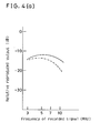
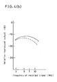
- Recording/reproducing was made on the tape sample by utilizing a ring-shaped magnetic head. Reproduced voltage was measured by changing frequency of signal.
- FIG.4(a) is a graph showing the frequency response of relative reproduced output of the Example 1 and the Comparison example 1.
- FIG.4(b) is a graph showing the frequency response of relative reproduced output of the Example 2 and the Comparison example 2.
- FIGs.4(a) and 4(b) show that relative reproduced output of the Examples 1 and 2 were higher than that of the Comparison examples 1 and 2 respectively.
- improvement of recording/reproducing characteristic is obtained by the method of the present invention for making the magnetic recording medium.
- Technical advantage of the present invention obtained in the Embodiment 1 was more remarkable than that obtained in the Embodiment 2, the reason why would be that by the Embodiment 2 a relatively thin oxidized layer was formed on the first magnetic layer in the Experiment 2.
- Both the first magnetic layer and the second one were formed in one vacuum chamber continuously, so that the second magnetic layer was formed without exposing the first magnetic layer under atmosphere, and thereby thinner oxidized layer than that of the Experiment 1 was formed in the Experiment 2.
- a dc voltage e.g. -150V is applied to the roller 11 against the cylindrical can 12 as the ground.
- accerelated ions 7 were irradiated onto the first magnetic layer 2
- the substrate 1 could not come closely into contact to the cylindrical can 12. The reason would be that somehow electrical charge on the substrate 1 due to the above-mentioned dc voltage was probably cancelled by the irradiated ions 7. And such insufficient contact results in deterioration of the substrate 1 due to heat from the evaporated atoms 14 through insufficient cooling effect of the cylindrical can 12.
- FIG.5 a third embodiment of the continuous evaporation apparatus is devided as shown in FIG.5.
- a conventional electron gun 19 was disposed in a manner that irradiation of electron beam 20 was made on a part of the substrate 1 between the guide roller 11 a and the cylindrical can 12.
- the electron beam 20 was irradiated onto opposite face of the substrate 1 to one face covered by the first magnetic layer 2.
- the electron beam 20 was produced under the following condition: the accelerating voltage of electrons was 2kV, and an emission current was 10mA.
- the electrons are stored in the substrate stably inside thereof, that is the electrons were not cancelled by the irradiated ions 7 on opposite face of the substrate to the face irradiated by the electron beam 20, or the electrons do not flow into the ground through the cylindrical can either.
- the substrate having enough charge due to the stored electrons could come closely into contact with the cylindrical can owing to electrostatic adhesion.
- the first magnetic layer 2 and the second magnetic layer 3 were made of materials chosen from the alloys: Co-O, Co-Ni-O, Co-Cr, Co-Ni-Cr and Co-V, these alloys including at least one element selected from transition metal elements in iron group such as Fe, Cu and Mn, noble metals such as Pt and Pd, and other elements such as C, B and P as additives.
Landscapes
- Chemical & Material Sciences (AREA)
- Crystallography & Structural Chemistry (AREA)
- Manufacturing Of Magnetic Record Carriers (AREA)
Applications Claiming Priority (2)
| Application Number | Priority Date | Filing Date | Title |
|---|---|---|---|
| JP197325/90 | 1990-07-25 | ||
| JP2197325A JPH0834001B2 (ja) | 1990-07-25 | 1990-07-25 | 磁気記録媒体の製造方法 |
Publications (2)
| Publication Number | Publication Date |
|---|---|
| EP0468488A1 true EP0468488A1 (de) | 1992-01-29 |
| EP0468488B1 EP0468488B1 (de) | 1996-11-27 |
Family
ID=16372588
Family Applications (1)
| Application Number | Title | Priority Date | Filing Date |
|---|---|---|---|
| EP91112452A Expired - Lifetime EP0468488B1 (de) | 1990-07-25 | 1991-07-24 | Verfahren zur Herstellung eines magnetischen Aufzeichnungsträgers |
Country Status (4)
| Country | Link |
|---|---|
| EP (1) | EP0468488B1 (de) |
| JP (1) | JPH0834001B2 (de) |
| KR (1) | KR960013372B1 (de) |
| DE (1) | DE69123299T2 (de) |
Cited By (6)
| Publication number | Priority date | Publication date | Assignee | Title |
|---|---|---|---|---|
| EP0573026A1 (de) * | 1992-06-05 | 1993-12-08 | Matsushita Electric Industrial Co., Ltd. | Magnetisches Aufzeichnungsmedium und Verfahren zu seiner Herstellung |
| EP0729134A1 (de) * | 1995-02-24 | 1996-08-28 | Kao Corporation | Magnetischer Aufzeichnungsträger |
| EP0688016A3 (de) * | 1994-06-17 | 1997-01-02 | Matsushita Electric Industrial Co Ltd | Methode und Vorrichtung zur Herstellung eines magnetischen Aufzeichnungsmediums |
| US5679410A (en) * | 1994-06-06 | 1997-10-21 | Matsushita Electric Industrial Co., Ltd. | Continuous fabrication of thin film magnetic recording medium with vacuum deposition |
| EP0808667A3 (de) * | 1996-05-21 | 1998-12-16 | Matsushita Electric Industrial Co., Ltd. | Dünnfilmelement, Verfahren und Vorrichtung zur Herstellung desselben und elektronische Vorrichtung mit demselben |
| WO2005045094A1 (en) * | 2003-11-04 | 2005-05-19 | Superpower, Inc. | A tape-manufacturing system having extended operational capabilities |
Families Citing this family (1)
| Publication number | Priority date | Publication date | Assignee | Title |
|---|---|---|---|---|
| WO2011122274A1 (ja) | 2010-03-30 | 2011-10-06 | ウシオ電機株式会社 | 高圧放電ランプ点灯装置 |
Citations (1)
| Publication number | Priority date | Publication date | Assignee | Title |
|---|---|---|---|---|
| DE3443601A1 (de) * | 1983-11-29 | 1985-06-13 | TDK Corporation, Tokio/Tokyo | Magnetaufzeichnungsmedium |
Family Cites Families (4)
| Publication number | Priority date | Publication date | Assignee | Title |
|---|---|---|---|---|
| JPS5712424A (en) * | 1980-06-26 | 1982-01-22 | Toshiba Corp | Production of magnetic recorder |
| JPS59107429A (ja) * | 1982-12-09 | 1984-06-21 | Sony Corp | 磁気記録媒体の製造装置 |
| JPS6124025A (ja) * | 1984-07-12 | 1986-02-01 | Hitachi Maxell Ltd | 磁気記録媒体の製造方法 |
| JPS6453346A (en) * | 1987-08-24 | 1989-03-01 | Matsushita Electric Industrial Co Ltd | Production of magnetic recording medium |
-
1990
- 1990-07-25 JP JP2197325A patent/JPH0834001B2/ja not_active Expired - Fee Related
-
1991
- 1991-07-24 EP EP91112452A patent/EP0468488B1/de not_active Expired - Lifetime
- 1991-07-24 DE DE69123299T patent/DE69123299T2/de not_active Expired - Fee Related
- 1991-07-25 KR KR1019910012767A patent/KR960013372B1/ko not_active Expired - Fee Related
Patent Citations (1)
| Publication number | Priority date | Publication date | Assignee | Title |
|---|---|---|---|---|
| DE3443601A1 (de) * | 1983-11-29 | 1985-06-13 | TDK Corporation, Tokio/Tokyo | Magnetaufzeichnungsmedium |
Non-Patent Citations (1)
| Title |
|---|
| PATENT ABSTRACTS OF JAPAN vol. 12, no. 102 (P-684)5 April 1988 & JP-A-62 234 239 ( MATSUSHITA ELECTRIC IND CO ) 14 October 1987 * |
Cited By (15)
| Publication number | Priority date | Publication date | Assignee | Title |
|---|---|---|---|---|
| EP0573026A1 (de) * | 1992-06-05 | 1993-12-08 | Matsushita Electric Industrial Co., Ltd. | Magnetisches Aufzeichnungsmedium und Verfahren zu seiner Herstellung |
| US5418059A (en) * | 1992-06-05 | 1995-05-23 | Matsushita Electric Industrial Co., Ltd. | Magnetic recording medium and method for producing the same |
| US5679410A (en) * | 1994-06-06 | 1997-10-21 | Matsushita Electric Industrial Co., Ltd. | Continuous fabrication of thin film magnetic recording medium with vacuum deposition |
| EP0688016A3 (de) * | 1994-06-17 | 1997-01-02 | Matsushita Electric Industrial Co Ltd | Methode und Vorrichtung zur Herstellung eines magnetischen Aufzeichnungsmediums |
| EP0729134A1 (de) * | 1995-02-24 | 1996-08-28 | Kao Corporation | Magnetischer Aufzeichnungsträger |
| US6153259A (en) * | 1996-05-21 | 2000-11-28 | Matsushita Electric Industrial Co., Ltd. | Thin film, method and apparatus for forming the same, and electronic component incorporating the same |
| EP0808667A3 (de) * | 1996-05-21 | 1998-12-16 | Matsushita Electric Industrial Co., Ltd. | Dünnfilmelement, Verfahren und Vorrichtung zur Herstellung desselben und elektronische Vorrichtung mit demselben |
| KR100330111B1 (ko) * | 1996-05-21 | 2002-11-27 | 마쯔시다덴기산교 가부시키가이샤 | 박막 제조 방법 및 장치 |
| US6488985B1 (en) | 1996-05-21 | 2002-12-03 | Matsushita Electric Industrial Co., Ltd. | Thin film, method and apparatus for forming the same, and electronic component incorporating the same |
| US6602559B1 (en) | 1996-05-21 | 2003-08-05 | Matsushita Electric Industrial Co., Ltd. | Thin film, method and apparatus for forming the same, and electronic component incorporating the same |
| US6714401B2 (en) | 1996-05-21 | 2004-03-30 | Matsushita Electric Industrial Co., Ltd. | Thin film, method and apparatus for forming the same, and electronic component incorporating the same |
| US6942903B2 (en) | 1996-05-21 | 2005-09-13 | Matsushita Electric Industrial Co., Ltd. | Thin film, method and apparatus for forming the same, and electronic component incorporating the same |
| US8480804B2 (en) | 1996-05-21 | 2013-07-09 | Panasonic Corporation | Thin film, method and apparatus for forming the same, and electronic component incorporating the same |
| WO2005045094A1 (en) * | 2003-11-04 | 2005-05-19 | Superpower, Inc. | A tape-manufacturing system having extended operational capabilities |
| US7914848B2 (en) | 2003-11-04 | 2011-03-29 | Superpower, Inc. | Tape-manufacturing system having extended operational capabilities |
Also Published As
| Publication number | Publication date |
|---|---|
| EP0468488B1 (de) | 1996-11-27 |
| KR920003267A (ko) | 1992-02-29 |
| JPH0489627A (ja) | 1992-03-23 |
| KR960013372B1 (ko) | 1996-10-04 |
| DE69123299D1 (de) | 1997-01-09 |
| DE69123299T2 (de) | 1997-06-19 |
| JPH0834001B2 (ja) | 1996-03-29 |
Similar Documents
| Publication | Publication Date | Title |
|---|---|---|
| US4495242A (en) | Magnetic recording medium | |
| EP0053811B1 (de) | Magnetische Aufzeichnungsmedien | |
| US4511594A (en) | System of manufacturing magnetic recording media | |
| EP0468488B1 (de) | Verfahren zur Herstellung eines magnetischen Aufzeichnungsträgers | |
| US4673610A (en) | Magnetic recording medium having iron nitride recording layer | |
| US4543301A (en) | Magnetic recording medium | |
| US4604293A (en) | Process for producing magnetic recording medium | |
| US5202149A (en) | Method for making a magnetic recording medium | |
| US4988535A (en) | Magnetic recording medium | |
| US7670693B2 (en) | Magnetic recording medium possessing a columnar structure | |
| JPH0546013B2 (de) | ||
| US4546725A (en) | Apparatus for manufacturing magnetic recording media | |
| US4526131A (en) | Magnetic recording medium manufacturing apparatus | |
| JP2946748B2 (ja) | 磁気記録媒体の製造方法 | |
| JPH0451888B2 (de) | ||
| JPH0418371B2 (de) | ||
| JPH0341899B2 (de) | ||
| JP2558753B2 (ja) | 磁気記録媒体 | |
| JPH0341898B2 (de) | ||
| JP2568643B2 (ja) | 磁気記録媒体の製造方法 | |
| JPS59178626A (ja) | 磁気記録媒体の製法 | |
| JPH10105945A (ja) | 磁気記録媒体 | |
| JPH01320637A (ja) | 磁気記録媒体の製造方法 | |
| JPH0967669A (ja) | スパッタリング装置 | |
| JPS62102414A (ja) | 磁気記録媒体 |
Legal Events
| Date | Code | Title | Description |
|---|---|---|---|
| PUAI | Public reference made under article 153(3) epc to a published international application that has entered the european phase |
Free format text: ORIGINAL CODE: 0009012 |
|
| 17P | Request for examination filed |
Effective date: 19910724 |
|
| AK | Designated contracting states |
Kind code of ref document: A1 Designated state(s): DE FR GB |
|
| 17Q | First examination report despatched |
Effective date: 19930908 |
|
| GRAH | Despatch of communication of intention to grant a patent |
Free format text: ORIGINAL CODE: EPIDOS IGRA |
|
| GRAH | Despatch of communication of intention to grant a patent |
Free format text: ORIGINAL CODE: EPIDOS IGRA |
|
| GRAA | (expected) grant |
Free format text: ORIGINAL CODE: 0009210 |
|
| AK | Designated contracting states |
Kind code of ref document: B1 Designated state(s): DE FR GB |
|
| ET | Fr: translation filed | ||
| REF | Corresponds to: |
Ref document number: 69123299 Country of ref document: DE Date of ref document: 19970109 |
|
| PLBE | No opposition filed within time limit |
Free format text: ORIGINAL CODE: 0009261 |
|
| STAA | Information on the status of an ep patent application or granted ep patent |
Free format text: STATUS: NO OPPOSITION FILED WITHIN TIME LIMIT |
|
| 26N | No opposition filed | ||
| REG | Reference to a national code |
Ref country code: GB Ref legal event code: IF02 |
|
| PGFP | Annual fee paid to national office [announced via postgrant information from national office to epo] |
Ref country code: FR Payment date: 20060719 Year of fee payment: 16 Ref country code: GB Payment date: 20060719 Year of fee payment: 16 |
|
| PGFP | Annual fee paid to national office [announced via postgrant information from national office to epo] |
Ref country code: DE Payment date: 20060720 Year of fee payment: 16 |
|
| GBPC | Gb: european patent ceased through non-payment of renewal fee |
Effective date: 20070724 |
|
| PG25 | Lapsed in a contracting state [announced via postgrant information from national office to epo] |
Ref country code: DE Free format text: LAPSE BECAUSE OF NON-PAYMENT OF DUE FEES Effective date: 20080201 |
|
| PG25 | Lapsed in a contracting state [announced via postgrant information from national office to epo] |
Ref country code: GB Free format text: LAPSE BECAUSE OF NON-PAYMENT OF DUE FEES Effective date: 20070724 |
|
| REG | Reference to a national code |
Ref country code: FR Ref legal event code: ST Effective date: 20080331 |
|
| PG25 | Lapsed in a contracting state [announced via postgrant information from national office to epo] |
Ref country code: FR Free format text: LAPSE BECAUSE OF NON-PAYMENT OF DUE FEES Effective date: 20070731 |