EP0468510B1 - Méthode pour déposer une substance sur un article - Google Patents
Méthode pour déposer une substance sur un article Download PDFInfo
- Publication number
- EP0468510B1 EP0468510B1 EP91112530A EP91112530A EP0468510B1 EP 0468510 B1 EP0468510 B1 EP 0468510B1 EP 91112530 A EP91112530 A EP 91112530A EP 91112530 A EP91112530 A EP 91112530A EP 0468510 B1 EP0468510 B1 EP 0468510B1
- Authority
- EP
- European Patent Office
- Prior art keywords
- substance
- chambers
- article
- loading zone
- disc
- Prior art date
- Legal status (The legal status is an assumption and is not a legal conclusion. Google has not performed a legal analysis and makes no representation as to the accuracy of the status listed.)
- Revoked
Links
- 239000000126 substance Substances 0.000 title claims description 89
- 238000000034 method Methods 0.000 title claims description 18
- 239000003205 fragrance Substances 0.000 claims description 28
- 239000002250 absorbent Substances 0.000 claims description 17
- 238000000605 extraction Methods 0.000 claims description 14
- 230000002745 absorbent Effects 0.000 claims description 12
- 230000009969 flowable effect Effects 0.000 claims description 12
- 238000000151 deposition Methods 0.000 claims description 10
- 230000008021 deposition Effects 0.000 claims description 4
- 239000000463 material Substances 0.000 claims description 4
- 230000005484 gravity Effects 0.000 claims description 3
- 239000003795 chemical substances by application Substances 0.000 description 24
- UIIMBOGNXHQVGW-UHFFFAOYSA-M Sodium bicarbonate Chemical compound [Na+].OC([O-])=O UIIMBOGNXHQVGW-UHFFFAOYSA-M 0.000 description 8
- 238000007790 scraping Methods 0.000 description 6
- 241000237858 Gastropoda Species 0.000 description 4
- 239000002245 particle Substances 0.000 description 4
- 229910000030 sodium bicarbonate Inorganic materials 0.000 description 4
- 235000017557 sodium bicarbonate Nutrition 0.000 description 4
- VYPSYNLAJGMNEJ-UHFFFAOYSA-N Silicium dioxide Chemical compound O=[Si]=O VYPSYNLAJGMNEJ-UHFFFAOYSA-N 0.000 description 2
- UIIMBOGNXHQVGW-DEQYMQKBSA-M Sodium bicarbonate-14C Chemical compound [Na+].O[14C]([O-])=O UIIMBOGNXHQVGW-DEQYMQKBSA-M 0.000 description 2
- 238000007666 vacuum forming Methods 0.000 description 2
- 229920002134 Carboxymethyl cellulose Polymers 0.000 description 1
- 239000004372 Polyvinyl alcohol Substances 0.000 description 1
- 239000001768 carboxy methyl cellulose Substances 0.000 description 1
- 235000010948 carboxy methyl cellulose Nutrition 0.000 description 1
- 239000008112 carboxymethyl-cellulose Substances 0.000 description 1
- 229920006037 cross link polymer Polymers 0.000 description 1
- 230000003628 erosive effect Effects 0.000 description 1
- 239000012530 fluid Substances 0.000 description 1
- 239000000499 gel Substances 0.000 description 1
- 239000000017 hydrogel Substances 0.000 description 1
- 210000003734 kidney Anatomy 0.000 description 1
- 238000004519 manufacturing process Methods 0.000 description 1
- 230000002093 peripheral effect Effects 0.000 description 1
- 229920002451 polyvinyl alcohol Polymers 0.000 description 1
- 238000007493 shaping process Methods 0.000 description 1
- 239000000377 silicon dioxide Substances 0.000 description 1
Images

Classifications
-
- B—PERFORMING OPERATIONS; TRANSPORTING
- B05—SPRAYING OR ATOMISING IN GENERAL; APPLYING FLUENT MATERIALS TO SURFACES, IN GENERAL
- B05C—APPARATUS FOR APPLYING FLUENT MATERIALS TO SURFACES, IN GENERAL
- B05C11/00—Component parts, details or accessories not specifically provided for in groups B05C1/00 - B05C9/00
- B05C11/10—Storage, supply or control of liquid or other fluent material; Recovery of excess liquid or other fluent material
Definitions
- This invention relates to a method of applying a substance to an article. It relates also to an apparatus for applying a substance to an article.
- a method of applying a substance to an article comprises rotating a plurality of circumferentially spaced metering chambers about an axis so that the chambers pass successively through a loading zone; depositing a flowable substance in the chambers as they move through the loading zone so that each chamber contains a fixed quantity of the substance as it passes from the loading zone; extracting the quantities of substance successively from the chambers in a discharge zone spaced from the loading zone, by means of negative pressure or suction; and applying the extracted quantities of substance to an article.
- metering chambers are provided in a horizontal disc rotating about a vertical axis, with the method including removing excess substance or material protruding from the chambers above the disc surface in the loading zone, thereby to provide the fixed or predetermined quantities of substance in the chambers.
- the chambers extend through the disc, with the extraction of the fixed or metered quantities of substance being effected from below the disc.
- the metering chambers are provided in the outer surface of a cylindrical member rotating about a horizontal axis.
- the method include removing excess substance protruding from the chambers above the cylinder surface in the loading zone.
- the substance extraction is effected in an upward direction.
- the extraction may be effected by sucking the quantities of substance from the chambers along a transfer conduit, and conveying the substance pneumatically along the transfer conduit.
- the transfer conduit outlet may discharge the substance onto the article.
- the method may include simultaneously effecting a negative airflow through the article, so that the substance is sucked onto the article.
- the flowable substance may be in particulate, eg powdered or granular, form.
- the method may be used particularly but not necessarily exclusively, in applying a particulate, eg powdered, super-absorbent substance, ie an inorganic or organic hydrogel substance capable of absorbing fluids, such as silica gels and cross-linked polymers, eg polyvinyl alcohol, carboxymethyl cellulose, and the like; or an anti-odourant agent, such as sodium bicarbonate, to an absorbent batt, to form a component for a sanitary towel, napkin, disposable diaper, or the like.
- a particulate, eg powdered, super-absorbent substance ie an inorganic or organic hydrogel substance capable of absorbing fluids, such as silica gels and cross-linked polymers, eg polyvinyl alcohol, carboxymethyl cellulose, and the like
- an anti-odourant agent such as sodium bicarbonate
- an apparatus for applying a substance to an article which apparatus comprises the following features of DE-A-1 184 976: a metering component rotatable about an axis and having a plurality of circumferentially spaced metering chambers therein; feed means for depositing a flowable substance successively in the chambers in a loading zone as the chambers move through the loading zone on rotation of the metering component so that each chamber contains a fixed quantity of the substance as it passes from the loading zone; vacuum extraction means for extracting the quantities of the substance successively from the chambers in a discharge zone spaced from the loading zone; and application means for applying the extracted quantities of substance to an article, wherein the feed means comprises a bulk vessel for the substance, and a feed conduit leading from the vessel, with the feed conduit having a discharge opening in the loading zone. The vessel and feed conduit are arranged such that the substance flows under gravity from the vessel through the feed conduit.
- the metering component comprises a horizontal cylinder, rotatable about a horizontally extending axis, with the transfer conduit inlet opening and being located adjacent the cylinder surface at a position above the horizontal plane in which the axis lies.
- the vacuum extraction means may comprise a transfer conduit having an inlet opening in the discharge zone, and vacuum generating means for generating a vacuum or negative pressure at the inlet opening end of the transfer conduit.
- the vacuum generating means may be a venturi mounted at or in proximity to the inlet opening end of the transfer conduit.
- the other outlet end of the transfer conduit may constitute at least part of the application means, with the transfer conduit outlet end being located in an application zone through which the article passes, in use.
- the substance may be a particulate anti-odourant substance such as sodium bicarbonate, with the article being a batt or layer of absorbent material, eg a batt or layer of ground pulp or the like, with the resultant batt or layer to which the sodium bicarbonate particles have been applied being suitable for use in forming personal hygiene or sanitary towels, napkins, diapers, or the like.
- a particulate anti-odourant substance such as sodium bicarbonate
- the article being a batt or layer of absorbent material, eg a batt or layer of ground pulp or the like, with the resultant batt or layer to which the sodium bicarbonate particles have been applied being suitable for use in forming personal hygiene or sanitary towels, napkins, diapers, or the like.
- the chambers may be spaced equidistantly from the centre of the disc so that they constitute a first set of chambers, with at least one further set of circumferentially spaced chambers, spaced a different distance from the disc centre, also being provided, with the feed means being adapted, eg by having a plurality of feed conduits, to deposit the substance into at least one chamber of each set simultaneously and with the extraction means being adapted, eg by having a plurality of transfer conduits, to extract the quantities of substance from at least one chamber of each set simultaneously.
- the metering component may comprise a horizontal cylinder, rotatable about a horizontally extending axis, with the transfer conduit inlet opening end being located adjacent the cylinder surface at a position above the horizontal plane in which the axis lies.
- At least one further set of circumferentially spaced chambers, spaced longitudinally from the other or first set of chambers, may then be provided.
- the feed means will then be adapted to deposit the substance simultaneously into at least one chamber of each set, and the extraction means adapted to extract the quantities of substance simultaneously from at least one chamber of each set, as hereinbefore described.
- the chambers may be shaped to give a desired deposition pattern of the substance on the article.
- the openings or recesses may be circular.
- other chamber shapes may be more suitable.
- the openings or recesses may be elongated and shingled in respect of one another so that at any given instant, one opening or recess or portions of adjacent openings or recesses are in register with the inlet opening of the transfer conduit so that a continuous stream of metered substance is deposited on the article.
- the apparatus may also include scraping means for scraping excess substance protruding from the chambers as they pass from the loading zone.
- the scraping means may then include the lower peripheral edge of the feed conduit discharge opening located immediately above the disc or cylinder surface.
- the apparatus may also include further scraping means for scraping any excess substance present on the disc upper surface into the chambers as the chambers approach the loading zone.
- the further scraping means may include a scraper plate immediately above, ie in sliding contact with, the disc upper surface.
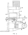
- reference numeral 10 generally indicates apparatus for applying flowable particulate anti-odourant agent to an absorbent batt or layer, according to one embodiment of the invention.
- the apparatus 10 includes a bulk vessel or hopper 12 for containing the particulate flowable anti-odourant agent such as sodium bicarbonate.
- the hopper 12 has a discharge nozzle 14 to which is fitted a flexible tube 16 defining a feed conduit.
- the other end of the feed conduit 16 is attached to a feed tube 18 mounted, by means of a bracket/clamp 20, to a mounting plate 22.
- the anti-odourant agent can hence flow under gravity through the tubes 16, 18.
- the lower end of the feed tube 18 terminates immediately above a rotatable metering disc 24, in a loading zone.
- the disc 24 is mounted to a boss 26, which is mounted to a vertical output shaft 28 of a right angle gearbox 30 having an input shaft 32.
- the input shaft 32 is operatively connected to apparatus 60, which is discussed in more detail hereunder, or to a suitable drive means (not shown) such as an electric motor.
- the disc 24 extends horizontally, and rotates about a vertically extending axis provided by the shaft 28.
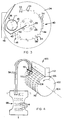
- the openings 34 can be arranged in pairs, as indicated in Figure 3, with the pairs of openings being spaced circumferentially apart or can be arranged singly as indicated at 38.
- the openings 34 are circular. However, in other embodiments of the invention, they can be any other desired shape, as indicated at 38 and 40 in Figure 3, and which are described in more detail hereunder.
- a scraper plate 42 is mounted adjacent the tube 18, and is in sliding contact with the upper surface of the disc 24.
- anti-odourant agent flowing from the hopper 12 into the feed tube 18 will fill the openings 34 immediately below the feed tube 18.
- excess material protruding above the openings 34 is scraped off the disc upper surface by means of the scraper plate 42. In this fashion, equal quantities of anti-odourant agent are loaded into each of the openings 34.
- venturi 50 Immediately below the disc 24, in a discharge zone 48, is mounted a venturi 50.
- the venturi 50 has an inlet opening aligned with the openings 34 and hence, in use, suction is generated in the zone 48 with this suction extracting the metered doses of anti-odourant agent from the chambers.
- Part of the tube 54 can be transparent, if desired, to monitor the 'slugs' of anti-odourant agent moving along it.
- the tube 54 leads from the venturi 50 to an apparatus, generally indicated by reference numeral 60.
- the apparatus 60 is more-or-less conventional and is capable of forming a batt or layer of absorbent ground pulp particles, and includes a hammermill 62 in which large pulp particles are comminuted, and continuous vacuum forming belt 64 on which the comminuted pulp particles or fluff are deposited as the batt or layer 66.
- the belt 64 is of mesh form, and the batt 66 is formed thereon by means of suction created by a vacuum fan 68.
- the tube 54 terminates in a application zone 70 in which the sodium bicarbonate is deposited on the batt 66.
- anti-odourant agent is transported along the tube 54 as hereinbefore described, in the form of separate 'slugs' passing along the tube 54.
- the tube 54 should be as short as possible, and preferably less than 2 m, eg the apparatus 10 can be located immediately above the batt 66 so that the slugs do not dissipate as a result of the friction in the tube, and to minimize erosion of the tube.
- These slugs of anti-odourant agent are then deposited at predetermined intervals on the batt 66.
- the zone 70 in which the outlet of the tube 54 is located is hence in an area which has a negative airflow through the layer 66 to which the anti-odourant agent is applied.
- the absorbent batt 66 will be cut into a desired shape to form components of sanitary towels, napkins, disposable diapers, or the like, in which the anti-odourant agent is located in a desired zone or position on each of the pads, eg at its centre.
- the volume of the openings 34 ie their diameter and the thickness of the disc, naturally determines the amount of anti-odourant agent deposited onto each sanitary device, with each group of openings 34 representing one dose of anti-odourant agent per sanitary device.
- the shape of the openings and the relative arrangement of the openings 34 determine the size and shape of the zone in which the anti-odourant agent is deposited on the article. For example, with the circular openings 34, arranged as indicated in Figure 3, it will be possible to deposit anti-odourant agent in a central zone in each sanitary towel.
- the openings 34 are located in a circle having a diameter of 160 mm, with the openings 34 each having a diameter of 6 mm, and 14 pairs of the openings being provided.
- openings 34 similar to those indicated at reference numeral 40 in Figure 3, can be used. These openings 34 are in the form of elongate slots arranged in such a fashion, that the one end of one slot overlaps the other end of an adjacent slot. Hence, when the slots 34 pass over the venturi 50, the venturi will continually be in register with at least a portion of one of the slots, so that the predetermined amounts of anti-odourant agent are transferred continually along the tube 54.
- a kidney shaped opening such as opening 34 such as that indicated at reference numeral 38 in Figure 3
- the length of the dose is thus variable from short intermittent pulses to a continuous line.
- the timing of the disc in relation to the movement of the layer along the belt 64, the position of the anti-odourant agent zones on the batt or layer 66 can thus be adjusted.
- reference numeral 100 generally indicates an apparatus for applying particulate flowable super-absorbant substance to an absorbent wad 66, according to another embodiment of the invention.
- the apparatus 100 has rotatable cylindrical metering drum 102.
- the drum 102 is mounted to rotate about a horizontal axis 104, in the direction of arrow 106, and is driven to rotate by suitable drive means (not shown).
- a plurality of oval recesses 108 are provided in the cylindrical surface 110 of the drum, with each recess providing a metering chamber.
- the recesses 108 are arranged in rows extending across the drum, with the rows being spaced circumferentially about the drum.
- a feed chute 112 leading from the bulk hopper is provided instead of the feed tube 18, a feed chute 112, leading from the bulk hopper.
- a scraper plate (not shown), similar to the scraper plate 42, may also be provided.
- a venturi 50 and transfer tube 54 is provided for each recess in a row of recesses extending across the drum, with the venturis being located above a horizontal plane in which the axis 104 is located.
- the apparatus 100 functions substantially similarly to the apparatus 10, save that, as a result of the plurality of recesses in each row, the super-absorbent substance can be deposited in discrete zones 114 spaced laterally across and longitudinally along the wad 66, which can be a diaper pulp panel, preformed by means of vacuum forming or by shaping a batt or layer.
- each comprising its own feed tube 18 and venturi 50 may be provided.
- large quantities of the particulate substance can be applied or quicker pulsing for high speed manufacture can be provided.
- apparatus 10, 100 super-absorbent or anti-odourant agent can be applied consistently and efficiently in accurate amounts, and in an accurately demarcated zones, on an absorbent batt, wad or layer, which can be processed further to ford sanitary towels, napkins, disposable diapers, or the like.
- the apparatus 10, 100 also have the advantage of being relatively inexpensive to fabricate, and operate.
Landscapes
- Absorbent Articles And Supports Therefor (AREA)
Claims (14)
- Procédé destiné à appliquer une substance à un article, ce procédé comprenant la rotation d,une pluralité de chambres de dosage espacées circonférentiellement (34, 38, 40, 108) autour d'un axe de sorte que les chambres passent successivement à travers une zone de chargement (36) ;
le dépôt d'une substance pouvant s'écouler dans les chambres (34, 38, 40, 108) au fur et à mesure qu'elles se déplacent à travers la zone de chargement (36) de sorte que chaque chambre contient une quantité déterminée de cette substance au fur et à mesure qu'elle passe depuis la zone de chargement (36) ;
l'extraction des quantités de substance successivement depuis les chambres dans une zone de décharge (48, 70) espacée de la zone de chargement (36), au moyen d'une pression négative ou d'une aspiration ; et
l'application des quantités extraites de substance à un article (66) ;
les chambres de dosage (34, 38, 40) étant prévues dans un disque horizontal (24) tournant autour d'un axe vertical (28), ce procédé comprenant l'élimination de la substance en excédent sortant des chambres au-dessus de la surface du disque dans la zone de chargement (36), de manière à distribuer les quantités de substance déterminées dans les chambres (34, 38, 40) ; caractérisé en ce que les chambres (34, 38, 40) s'étendent à travers le disque (24), l'extraction des quantités de substance étant effectuée depuis le haut du disque (24). - Procédé destiné à appliquer une substance à un article, ce procédé comprenant la rotation d'une pluralité de chambre de dosage espacées circonférentiellement (34, 38, 40, 108) autour d'un axe de sorte que les chambres passent successivement à travers une zone de chargement (36) ;
le dépôt d'une substance pouvant s'écouler dans les chambres (34, 38, 40, 108) au fur et à mesure qu'elles se déplacent à travers la zone de chargement (36) de sorte que chaque chambre contient une quantité déterminée de cette substance au fur et à mesure qu'elle passe depuis la zone de chargement (36);
l'extraction des quantités de substance successivement depuis les chambres dans une zone de décharge (48, 70) espacée de la zone de chargement (36), au moyen d'une pression négative ou d'une aspiration ; et
l'application des quantités extraites de substance à un article (66) ;
caractérisé en ce que les chambres de dosage (108) sont prévues sur la surface extérieure d'un élément cylindrique (102) tournant autour d'un axe horizontal (104), ce procédé comprenant l'éliminaticn de la substance en excédent sortant des chambres (108) au-dessus de la surface cylindrique (110) dans la zone de chargement (36), et effectuant l'extraction de la substance dans une direction vers le haut. - Procédé selon l'une quelconque des revendications 1 ou 2, caractérisé en ce que l'extraction est effectuée en aspirant les quantités de substance depuis les chambres (34, 38, 40, 108) le long d'un tuyau de transfert (54), et en transportant la substance pneumatiquement le long du tuyau de transfert (54).
- Procédé selon la revendication 3, caractérisé en ce que la sortie du tuyau de transfert décharge la substance sur l'article (66), ce procédé comprenant simultanément le fait de créer un flux d'air négatif à travers l'article (66), de sorte que la substance est aspirée sur l'article (66).
- Procédé selon l'une quelconque des revendications 1 à 4, caractérisé en ce que la substance pouvant s'écouler est prévue de manière à être une substance particulaire super absorbante, ou une substance anti-odeurs, et en ce que la nappe absorbante (66) est prévue le long de l'article auquel est distribuée la substance pouvant s'écouler.
- Dispositif destiné à appliquer une substance à un article, le dispositif comprenant- un composant de dosage consistant en un disque horizontal (24) pouvant tourner autour d'un axe (28) et ayant une pluralité de chambres de dosage espacées circonférentiellement (34; 38, 40) dans celui-ci ;- des moyens de distribution (18) destinés à déposer une substance pouvant s'écouler successivement dans les chambres dans une zone de chargement (36) au fur et à mesure que les chambres se déplacent à travers la zone de chargement (36) sur rotation du composant de dosage (24), de sorte que chaque chambre contient une quantité déterminée de cette substance au fur et à mesure qu'elle passe depuis la zone de chargement (36) ;- des moyens d'extraction par le vide (50, 52) destinés à extraire les quantités de cette substance successivement depuis les chambres dans une zone de décharge (48) espacée de la zone de chargement (36) ; et- des moyens d'application (54, 70) destinés à appliquer les quantités extraites de substance sur un article, dans lequel- les moyens de distribution (18, 102) comprennent une cuve volumineuse (12) pour la substance, et un tuyau de distribution (18) partant de la cuve (12), le tuyau de distribution (18) ayant une ouverture de décharge dans la zone de chargement (36), la cuve (12) et le tuyau de distribution (18) étant agencés de telle sorte que la substance s'écoule, sous l'effet de la gravité, de la cuve (12) à travers le tuyau de distribution (18) ;caractérisé en ce que- chaque chambre comprend une ouverture (34, 38, 40) s'étendant à travers le disque (24), avec- le composant de dosage comprenant également un élément de fermeture (46) situé au-dessous du disque (24) et en contact coulissant avec la surface inférieure du disque (24) dans la zone de chargement (36), mais pas dans la zone de décharge (48), de sorte que les quantités de substance peuvent être déchargées depuis le côté inférieur du disque (24) dans la zone de décharge (48), et une extrémité d'ouverture d'admission du tuyau de transfert étant située au-dessous du disque (24).
- Dispositif destiné à appliquer une substance à un article, comprenant- un composant de dosage pouvant tourner autour d'un axe et ayant- une pluralité de chambres de dosage (108) espacées circonférentiellement dans celui-ci ;- des moyens de distribution (112) destinés à déposer une substance pouvant s'écouler successivement dans les chambres (108) dans une zone de chargement au fur et à mesure que les chambres (108) se déplacent à travers la zone de chargement sur rotation du composant de dosage de sorte que chaque chambre (108) contient une quantité déterminée de cette substance au fur et à mesure qu'elle passe depuis la zone de chargement ;- des moyens d'extraction par le vide (50) destinés à extraire les quantités de cette substance successivement depuis les chambres (108) dans une zone de décharge espacée de la zone de chargement ; et- des moyens d'application (54) destinés à appliquer les quantités extraites de substance à un article,caractérisé en ce que- le composant de dosage comprend un cylindre horizontal (102), pouvant tourner autour d'un axe (104) s'étendant horizontalement,- une extrémité d'ouverture d'admission du tuyau de transfert étant située adjacente à la surface du cylindre (110) à une position au-dessus du plan horizontal dans lequel se trouve l'axe (104).
- Dispositif selon la revendication 6 ou 7, caractérisé en ce que les moyens d'extraction par le vide comprennent un tuyau de transfert (54) ayant une ouverture d'admission dans la zone de décharge (48), et des moyens de génération de vide destinés à générer un vide ou une pression négative à l'extrémité d'ouverture d'admission du tuyau de transfert (54).
- Dispositif selon la revendication 8, caractérisé en ce que les moyens de génération de vide sont un tube de venturi (50) monté sur ou à proximité de l'extrémité d'ouverture d'admission du tuyau de transfert (54).
- Dispositif selon la revendication 8 ou 9, caractérisé en ce que l'autre extrémité de sortie du tuyau de transfert (54) constitue au moins une partie des moyens d'application, l'extrémité de sortie du tuyau de transfert étant située dans une zone d'application (70) à travers laquelle passe l'article, en utilisation, et dans lequel la substance est une substance anti-odeurs particulaire et l'article est une nappe ou une couche (66) de matériau absorbant.
- Dispositif selon l'une quelconque des revendications 6 ou 8 à 10, caractérisé en ce que les chambres (34, 38) sont espacées de manière équidistante du centre (28) du disque (24) et constituent un premier ensemble de chambres (34), au moins un autre ensemble de chambres (38) espacées circonférentiellement, espacées d'une distance différente du centre du disque (28), étant également prévu, les moyens de distribution (18) étant adaptés pour déposer la substance dans au moins une chambre (34, 38) de chaque ensemble simultanément et les moyens d'extraction étant adaptés pour extraire les quantités de substance depuis au moins une chambre (34, 38, 40) de chaque ensemble simultanément.
- Dispositif selon la revendication 7, caractérisé en ce qu'au moins un autre ensemble de chambres (108) espacées circonférentiellement, espacé longitudinalement de l'autre ou premier ensemble de chambres (108), est prévu, les moyens de distribution (112) étant adaptés pour déposer la substance simultanément dans au moins une chambre (108) de chaque ensemble, et les moyens d'extraction (50) étant adaptés pour extraire les quantités de substance simultanément depuis au moins une chambre (108) de chaque ensemble.
- Dispositif selon l'une quelconque des revendications 6 à 12, caractérisé en ce que les chambres (34) sont circulaires, un dépôt de la substance dans une zone centrale ou similaire (114) de l'article étant obtenu.
- Dispositif selon l'une quelconque des revendications 6 à 13, caractérisé en ce que les chambres (34) sont allongées et en forme de galets l'une par rapport à l'autre de sorte qu'à tout instant donné, une chambre (34) ou parties des chambres adjacentes (34) sont en face de l'ouverture d'admission (50) du tuyau de transfert (54) de sorte qu'un courant continu de substance dosée est déposé sur l'article.
Applications Claiming Priority (2)
| Application Number | Priority Date | Filing Date | Title |
|---|---|---|---|
| ZA905894 | 1990-07-26 | ||
| ZA905894 | 1990-07-26 |
Publications (3)
| Publication Number | Publication Date |
|---|---|
| EP0468510A2 EP0468510A2 (fr) | 1992-01-29 |
| EP0468510A3 EP0468510A3 (en) | 1992-05-20 |
| EP0468510B1 true EP0468510B1 (fr) | 1996-05-15 |
Family
ID=25580222
Family Applications (1)
| Application Number | Title | Priority Date | Filing Date |
|---|---|---|---|
| EP91112530A Revoked EP0468510B1 (fr) | 1990-07-26 | 1991-07-25 | Méthode pour déposer une substance sur un article |
Country Status (10)
| Country | Link |
|---|---|
| US (1) | US5151301A (fr) |
| EP (1) | EP0468510B1 (fr) |
| AU (2) | AU655427B2 (fr) |
| BR (1) | BR9103197A (fr) |
| CA (1) | CA2047892C (fr) |
| DE (1) | DE69119497T2 (fr) |
| ES (1) | ES2087189T3 (fr) |
| GR (1) | GR1001092B (fr) |
| MX (1) | MX9100399A (fr) |
| NZ (1) | NZ239119A (fr) |
Families Citing this family (6)
| Publication number | Priority date | Publication date | Assignee | Title |
|---|---|---|---|---|
| US5429788A (en) * | 1994-03-28 | 1995-07-04 | Kimberly-Clark Corporation | Apparatus and method for depositing particulate material in a composite substrate |
| US6355330B1 (en) | 1997-03-07 | 2002-03-12 | Koslow Technologies Corporation | Continuous solid state web coating process and webs produced thereby |
| US6485813B1 (en) | 1997-03-07 | 2002-11-26 | Koslow Technologies Corp. | Method of stabilizing composite media and media produced thereby |
| US5792513A (en) * | 1997-03-07 | 1998-08-11 | Koslow Technologies Corporation | Continuous solid state web coating process |
| EP0979682A1 (fr) * | 1998-08-13 | 2000-02-16 | B a r m a g AG | Doseur de poudres avec disque de dosage |
| AU2001250971A1 (en) * | 2000-06-16 | 2002-01-02 | Ronald S. Pole | Perspiration absorbing items |
Family Cites Families (5)
| Publication number | Priority date | Publication date | Assignee | Title |
|---|---|---|---|---|
| CA686283A (en) * | 1964-05-12 | Plastic Protection (Proprietary) Limited | Spray coating | |
| DE1184976B (de) * | 1961-04-13 | 1965-01-07 | British Cellophane Ltd | Vorrichtung zur Verteilung gepulverter Stoffe |
| JPS5646426A (en) * | 1979-09-25 | 1981-04-27 | Color Toronitsuku Kk | Volumetric device of powder/grain substance |
| JPS6191326U (fr) * | 1984-11-21 | 1986-06-13 | ||
| FR2575825B1 (fr) * | 1985-01-04 | 1987-04-17 | Saint Gobain Vitrage | Procede et dispositif pour le dosage de matieres pulverulentes |
-
1991
- 1991-07-19 GR GR910100320A patent/GR1001092B/el not_active IP Right Cessation
- 1991-07-23 US US07/734,388 patent/US5151301A/en not_active Expired - Lifetime
- 1991-07-24 AU AU81308/91A patent/AU655427B2/en not_active Expired
- 1991-07-24 NZ NZ239119A patent/NZ239119A/en not_active IP Right Cessation
- 1991-07-25 BR BR919103197A patent/BR9103197A/pt not_active IP Right Cessation
- 1991-07-25 ES ES91112530T patent/ES2087189T3/es not_active Expired - Lifetime
- 1991-07-25 CA CA002047892A patent/CA2047892C/fr not_active Expired - Lifetime
- 1991-07-25 DE DE69119497T patent/DE69119497T2/de not_active Revoked
- 1991-07-25 EP EP91112530A patent/EP0468510B1/fr not_active Revoked
- 1991-07-26 MX MX9100399A patent/MX9100399A/es unknown
-
1994
- 1994-11-24 AU AU79025/94A patent/AU681911B2/en not_active Expired
Also Published As
| Publication number | Publication date |
|---|---|
| ES2087189T3 (es) | 1996-07-16 |
| DE69119497T2 (de) | 1996-09-26 |
| GR1001092B (el) | 1993-04-28 |
| EP0468510A3 (en) | 1992-05-20 |
| BR9103197A (pt) | 1992-02-18 |
| NZ239119A (en) | 1994-04-27 |
| AU681911B2 (en) | 1997-09-11 |
| AU8130891A (en) | 1992-01-30 |
| GR910100320A (en) | 1992-08-26 |
| CA2047892A1 (fr) | 1992-01-27 |
| DE69119497D1 (de) | 1996-06-20 |
| AU655427B2 (en) | 1994-12-22 |
| AU7902594A (en) | 1995-01-27 |
| MX9100399A (es) | 1992-08-10 |
| CA2047892C (fr) | 2001-07-24 |
| US5151301A (en) | 1992-09-29 |
| EP0468510A2 (fr) | 1992-01-29 |
Similar Documents
| Publication | Publication Date | Title |
|---|---|---|
| CN1050278C (zh) | 间断性地向纤维衬垫上喷射细粒粉末材料的方法和设备 | |
| US5750066A (en) | Method for forming an intermittent stream of particles for application to a fibrous web | |
| EP1082081B1 (fr) | Procede et dispositif permettant de former par soufflage des ames absorbantes fibreuses | |
| KR100628390B1 (ko) | 입자의 펄스 흐름 생성방법 및 펄스화 장치 | |
| JP6756706B2 (ja) | 高速sap粒子アプリケータ | |
| US9545616B2 (en) | Method and apparatus for applying particulate | |
| AU606648B2 (en) | Moisture-absorbent substrate | |
| EP0468510B1 (fr) | Méthode pour déposer une substance sur un article | |
| CN1750884A (zh) | 产生颗粒脉冲流的方法和装置 | |
| JPH06510015A (ja) | 粒状材料の分布器 | |
| EP2952263B1 (fr) | Procédé et appareil d'application de matières particulaires | |
| JP5037752B2 (ja) | 衛生製品のための前もって形状化された吸収性パッド製作装置 | |
| JP3970881B2 (ja) | 粒子のパルス化された流れをつくる方法および装置 | |
| HK1012925B (en) | Method and apparatus for forming an intermittent stream of particles for application to a fibrous web | |
| HK1089407A (en) | Method and apparatus for creating a pulsed stream of particles |
Legal Events
| Date | Code | Title | Description |
|---|---|---|---|
| PUAI | Public reference made under article 153(3) epc to a published international application that has entered the european phase |
Free format text: ORIGINAL CODE: 0009012 |
|
| AK | Designated contracting states |
Kind code of ref document: A2 Designated state(s): DE ES FR GB IT |
|
| PUAL | Search report despatched |
Free format text: ORIGINAL CODE: 0009013 |
|
| AK | Designated contracting states |
Kind code of ref document: A3 Designated state(s): DE ES FR GB IT |
|
| 17P | Request for examination filed |
Effective date: 19921103 |
|
| 17Q | First examination report despatched |
Effective date: 19940307 |
|
| GRAH | Despatch of communication of intention to grant a patent |
Free format text: ORIGINAL CODE: EPIDOS IGRA |
|
| GRAA | (expected) grant |
Free format text: ORIGINAL CODE: 0009210 |
|
| AK | Designated contracting states |
Kind code of ref document: B1 Designated state(s): DE ES FR GB IT |
|
| REG | Reference to a national code |
Ref country code: ES Ref legal event code: BA2A Ref document number: 2087189 Country of ref document: ES Kind code of ref document: T3 |
|
| REF | Corresponds to: |
Ref document number: 69119497 Country of ref document: DE Date of ref document: 19960620 |
|
| REG | Reference to a national code |
Ref country code: ES Ref legal event code: FG2A Ref document number: 2087189 Country of ref document: ES Kind code of ref document: T3 |
|
| ITF | It: translation for a ep patent filed | ||
| ET | Fr: translation filed | ||
| PLBQ | Unpublished change to opponent data |
Free format text: ORIGINAL CODE: EPIDOS OPPO |
|
| PLBI | Opposition filed |
Free format text: ORIGINAL CODE: 0009260 |
|
| PLBQ | Unpublished change to opponent data |
Free format text: ORIGINAL CODE: EPIDOS OPPO |
|
| PLBF | Reply of patent proprietor to notice(s) of opposition |
Free format text: ORIGINAL CODE: EPIDOS OBSO |
|
| 26 | Opposition filed |
Opponent name: PAUL HARTMANN AKTIENGESELLSCHAFT Effective date: 19970215 Opponent name: SANTEX AG Effective date: 19970213 |
|
| PGFP | Annual fee paid to national office [announced via postgrant information from national office to epo] |
Ref country code: FR Payment date: 19970709 Year of fee payment: 7 |
|
| PGFP | Annual fee paid to national office [announced via postgrant information from national office to epo] |
Ref country code: GB Payment date: 19970716 Year of fee payment: 7 |
|
| PGFP | Annual fee paid to national office [announced via postgrant information from national office to epo] |
Ref country code: ES Payment date: 19970729 Year of fee payment: 7 |
|
| PGFP | Annual fee paid to national office [announced via postgrant information from national office to epo] |
Ref country code: DE Payment date: 19970801 Year of fee payment: 7 |
|
| PLBF | Reply of patent proprietor to notice(s) of opposition |
Free format text: ORIGINAL CODE: EPIDOS OBSO |
|
| RDAH | Patent revoked |
Free format text: ORIGINAL CODE: EPIDOS REVO |
|
| RDAG | Patent revoked |
Free format text: ORIGINAL CODE: 0009271 |
|
| STAA | Information on the status of an ep patent application or granted ep patent |
Free format text: STATUS: PATENT REVOKED |
|
| 27W | Patent revoked |
Effective date: 19980606 |
|
| GBPR | Gb: patent revoked under art. 102 of the ep convention designating the uk as contracting state |
Free format text: 980606 |