EP0468571B1 - Vérin à commande hydraulique et retour pneumatique pour soupape - Google Patents
Vérin à commande hydraulique et retour pneumatique pour soupape Download PDFInfo
- Publication number
- EP0468571B1 EP0468571B1 EP91201850A EP91201850A EP0468571B1 EP 0468571 B1 EP0468571 B1 EP 0468571B1 EP 91201850 A EP91201850 A EP 91201850A EP 91201850 A EP91201850 A EP 91201850A EP 0468571 B1 EP0468571 B1 EP 0468571B1
- Authority
- EP
- European Patent Office
- Prior art keywords
- valve
- piston
- mechanism portion
- chamber
- air
- Prior art date
- Legal status (The legal status is an assumption and is not a legal conclusion. Google has not performed a legal analysis and makes no representation as to the accuracy of the status listed.)
- Expired - Lifetime
Links
- 230000007246 mechanism Effects 0.000 claims description 60
- 238000013016 damping Methods 0.000 claims description 53
- 239000012530 fluid Substances 0.000 claims description 40
- 238000013519 translation Methods 0.000 claims description 22
- 238000002485 combustion reaction Methods 0.000 claims description 10
- 230000006835 compression Effects 0.000 claims description 4
- 238000007906 compression Methods 0.000 claims description 4
- 230000033001 locomotion Effects 0.000 description 28
- 230000014616 translation Effects 0.000 description 12
- 230000008901 benefit Effects 0.000 description 6
- 230000006870 function Effects 0.000 description 4
- 235000014676 Phragmites communis Nutrition 0.000 description 3
- 230000009977 dual effect Effects 0.000 description 3
- 238000011084 recovery Methods 0.000 description 3
- 230000009467 reduction Effects 0.000 description 3
- 230000009471 action Effects 0.000 description 2
- 238000013459 approach Methods 0.000 description 2
- 238000004146 energy storage Methods 0.000 description 2
- 230000006872 improvement Effects 0.000 description 2
- 238000000034 method Methods 0.000 description 2
- 230000008569 process Effects 0.000 description 2
- 230000001105 regulatory effect Effects 0.000 description 2
- 230000004044 response Effects 0.000 description 2
- 238000013022 venting Methods 0.000 description 2
- 241001274197 Scatophagus argus Species 0.000 description 1
- 230000001276 controlling effect Effects 0.000 description 1
- 238000013461 design Methods 0.000 description 1
- 238000011161 development Methods 0.000 description 1
- 230000018109 developmental process Effects 0.000 description 1
- 230000003993 interaction Effects 0.000 description 1
- 230000014759 maintenance of location Effects 0.000 description 1
- 239000000463 material Substances 0.000 description 1
- 230000003534 oscillatory effect Effects 0.000 description 1
- 238000005381 potential energy Methods 0.000 description 1
- 230000000717 retained effect Effects 0.000 description 1
- 230000002441 reversible effect Effects 0.000 description 1
- 238000000926 separation method Methods 0.000 description 1
- 230000007704 transition Effects 0.000 description 1
Images


Classifications
-
- F—MECHANICAL ENGINEERING; LIGHTING; HEATING; WEAPONS; BLASTING
- F01—MACHINES OR ENGINES IN GENERAL; ENGINE PLANTS IN GENERAL; STEAM ENGINES
- F01L—CYCLICALLY OPERATING VALVES FOR MACHINES OR ENGINES
- F01L9/00—Valve-gear or valve arrangements actuated non-mechanically
- F01L9/10—Valve-gear or valve arrangements actuated non-mechanically by fluid means, e.g. hydraulic
Definitions
- the present invention relates to an asymmetrical bistable hydraulically powered actuator mechanism comprising a replenishable source of high pressure hydraulic fluid for causing translation of a portion of the mechanism from an initial position in one direction; a first damping chamber in which air is compressed during translation of the mechanism portion in said one direction, compression of the air slowing the translation in said one direction of the mechanism portion; means for temporarily preventing reversal of the direction of translation of the mechanism portion when the translation of the mechanism portion slows to a stop; means operable on command for disabling the temporarily preventing means so as to free the mechanism portion and move the mechanism portion in a direction opposite said one direction under the influence of the pressure of the air compressed in the first damping chamber; and a second damping chamber in which air is compressed during the translation of the mechanism portion in the direction opposite said one direction for damping and slowing the translation of the mechanism portion as it returns to the initial position.
- the invention also relates to an electronically controllable valve mechanism comprising an engine intake or exhaust valve, which is suitable for use in an internal combustion engine and is provided with an elongated valve stem, wherein the valve stem is moveable in the direction of stem elongation by an asymmetrical bistable hydraulically powered actuator mechanism according to the invention.
- EP-A-0 352 861 there is disclosed a computer control system which receives a plurality of engine operation sensor inputs and in turn controls a plurality of engine operating parameters including ignition timing and the time in each cycle of the opening and closing of the intake and exhaust valves among others.
- U.S. Patent 4,009,695 discloses hydraulically actuated valves in turn controlled by spool valves which are themselves controlled by a dashboard computer which monitors a number of engine operating parameters.
- This patent references many advantages which could be achieved by such independent valve control, but is not, due to its relatively slow acting hydraulic nature, capable of achieving these advantages.
- the patented arrangement attempts to control the valves on a real time basis so that the overall system is one with feedback and subject to the associated oscillatory behaviour.
- EP-A-0 328 195 there is disclosed a somewhat similar valve actuating device which employs a release type mechanism rather than a repulsion scheme as in the previously identified U.S. Patent.
- the disclosed device in this application is a jointly pneumatically and electromagnetically powered valve with high pressure air supply and control valving to use the air for both damping and as one motive force.
- the magnetic motive force is supplied from the magnetic latch opposite the one being released and this magnetic force attracts an armature of the device so long as the magnetic field of the first latch is in its reduced state. As the armature closes on the opposite latch, the magnetic attraction increases and overpowers that of the first latch regardless of whether it remains in the reduced state or not.
- a main or working piston which drives the engine valve and which is, in turn powered by compressed air.
- the power or working piston which moves the engine valve between open and closed positions is separated from the latching components and certain control valving structures so that the mass to be moved is materially reduced allowing very rapid operation. Latching and release forces are also reduced. Those valving components which have been separated from the main piston need not travel the full length of the piston stroke, leading to some improvement in efficiency.
- Compressed air is supplied to the working piston by a pair of control valves with that compressed air driving the piston from one position to another as well as typically holding the piston in a given position until a control valve is again actuated.
- the control valves are held closed by permanent magnets and opened by pneumatic force on the control valve when an electrical pulse to a coil near the permanent magnet neutralizes the attractive force of the magnet.
- EP-A-0 443 218 there is disclosed a hydraulically powered valve actuating mechanism including, inter alia, a high presuure hydraulic fluid accumulator in close proximity to the cavity in which the fluid is to do its work. It is somewhere between inefficient and impossible to move hydraulic fluid over a wide temperature range rapidly through long lines of relatively small cross-section.
- This application provides a chamber expandable against spring-loaded pistons in very close proximity to the working chamber of the actuator to which high pressure fluid is continuously supplied and from which a larger volume of fluid may be efficiently intermittently removed.
- an actuator piston is propelled from a valve-closed toward a valve-pen position and utilizes the air which is compressed during the damping process to power the actuator back to its initial or valve-closed position.
- an actuator capture or latching arrangement such as a hydraulic latch, is used in this recent invention to assure that the actuator does not immediately rebound, but rather remains in the valve-open position until commanded to return to its initial position.
- the initial translation of the actuator piston in this recent application is powered by pneumatic energy and requires a relatively large source pump as well as relatively large individual valve actuators.
- An asymmetrical bistable hydraulically powered actuator mechanism as mentioned in the opening paragraph is known from DE-A-31 39 399.
- the known actuator mechanism serves to actuate an engine inlet or exhaust valve in an internal combustion engine.
- the air which is compressed in the first damping chamber, acts on a piston fixed to a valve stem to bias the valve to its initial position in which a valve head is pressed against a valve seat.
- this compressed air acts as a stressed return spring tending to return the valve to its initial position with the valve head in contact with the valve scat.
- air is compressed in the second damping chamber, so that the valve is slowed as it returns to its initial position.
- a disadvantage of this known mechanism is that the damping force of the second damping chamber is not accurately determined as a function of the position of the valve head, so that the valve head or the valve seat may be damaged when the valve is returned to its initial position by the compressed air.
- an asymmetrical bistable valve actuator of improved design the provision of a hydraulically driven, pneumatically returned valve actuator; the provision of an increased pressure, reduced size hydraulic capture arrangement for temporarily delaying the return of an internal combustion engine to its valve-closed position; the provision of individually adjustable dual damping features in a valve actuator; and an arrangement in an internal combustion engine valve actuator for easing the valve gently yet solidly into its valve-closed position.
- the asymmetrical bistable hydraulically powered actuator mechanism is characterized in that the mechanism further comprises a first adjustable aperture allowing air to escape from the second damping chamber during less than the entire travel of the mechanism portion back to the initial position and a second adjustable aperture for allowing air to escape from the second damping chamber during the entire travel of the mechanism portion back to the initial position.
- first and second adjustable apertures By the use of said first and second adjustable apertures the mechanism portion smoothly returns to the initial position.
- the coaction of the first and second apertures provides a preliminary mild damping of the motion of the mechanism portion and the subsequent action of the second aperture only provides a more severe final damping of the mechanism portion motion. In this way, a controlled damping of the mechanism portion motion is achieved when the mechanism portion returns into the initial position, so that damage of the valve coupled to the mechanism portion or of the valve seat is avoided as much as possible.
- an asymmetrical bistable hydraulically powered actuator mechanism which comprises a second damping chamber for slowing the mechanism portion as it returns to the initial position
- EP-A-0 391 507 European patent application EP-A-0 391 507, which was published after the priority date of the present application but has a priority date before the priority date of the present application.
- pressure is exerted upon a hydraulic fluid as the mechanism portion returns to its initial position.
- the present invention takes advantage of many of the developments disclosed in the copending application EP-A-0 468 548 while the initial powered translation is accomplished by hydraulic energy from a hydraulic pump rather than by pneumatic energy.
- Hydraulic energy propulsion yields the advantages of reduced actuator size and, therefore, is easier to package, as well as a reduction of the size of and, therefore, the space required underneath a vehicle hood by the hydraulic pump.
- the compression of latching air and pneumatic energy recovery feature is accomplished in a smaller chamber than taught in copending application EP-A-0 468 548.
- the reduction in size is accompanied by a correlative increase in peak pressure of the compressed air.
- the latching pressure must be correspondingly increased, and in particular, a decrease in piston diameter to one-half the former value requires a corresponding four-fold increase in pressure to maintain the same overall latching force.
- the present invention also utilizes a third chamber behind the energy recovery piston which functions as the primary damping chamber for piston motion near the end of its return trip to the valve-closed position. It is not only important to damp piston motion as the internal combustion engine valve nears its closed position allowing the valve to gracefully close, it is also important to insure that the valve is fully and positively seated.
- a dual damping function with an arrangement for individually adjusting each step of the damping process assures gentle seating of the engine poppet valve.
- the present invention utilizes a closely coupled fluid accumulator to assure a rapid flow of the non-compressible fluid into the actuator.
- a bladder type accumulator with the fluid supply therein being continuously replenished and with the fluid supply being refilled or catching up between actuator translations is utilized along with a low viscosity, high viscosity index fluid having a broad temperature range to insure rapid response under a wide range of conditions as the fluid travels from the accumulator, through a one-way valve and into the actuator.
- a spring loaded high pressure accumulator as disclosed in the above-mentioned application EP-A-0 443 218 may be employed.
- a bistable electronically controlled hydraulically powered transducer has an armature which is reciprocable between first and second positions along with a hydraulic arrangement for powering the armature from the first position to the second position.
- armature which is reciprocable between first and second positions along with a hydraulic arrangement for powering the armature from the first position to the second position.
- pneumatic energy storage chamber in which air is compressed during motion of the armature from the first position to the second position with the compression of the air damping or slowing armature motion as it nears the second position.
- Reversal of armature motion when the motion of the armature has slowed to a stop is temporarily prevented by a hydraulic latch which is disableable on command to allow the air compressed in the chamber to return the armature to the first position.
- the hydraulic latch and the hydraulic powering arrangement may utilize the same hydraulic chamber.
- This controlled venting of air from the second chamber is achieved by a first adjustable aperture which allows air to escape from the chamber during less than the entire travel of the armature back from the second position to the first position, and a second adjustable aperture which allows air to escape from the chamber the entire time the armature is travelling back to the first position.
- These two apertures act together to provide a preliminary mild damping of armature motion.
- the first aperture is closed by armature motion part way through the transition and subsequent action of the second aperture by itself provides a more severe final damping of the armature motion.
- There is a hydraulic fluid accumulator located in close proximity to the area of the armature which is powered by the fluid for continuously receiving high pressure fluid and intermittently supplying fluid to power the armature. The closely adjacent accumulator insures a rapid, low loss response by the armature.
- the piston is hydraulic unilaterally moved, thereby causing the engine valve to move in the direction of stem elongation from a valve-closed to a valve-open position.
- the hydraulic source for powering the piston may include a hydraulic fluid accumulator in close proximity to the area of the piston for continuously receiving high pressure fluid and intermittently supplying fluid to power the piston.
- a pneumatic damping arrangement is provided for compressing a volume of air and imparting a continuously increasing decelerating force as the engine valve approaches the valve-open position. Finally, the compressed volume of air is utilized on command to power the piston back to the valve-closed position.
- the present invention utilizes hydraulic fluid to power an actuator from an initial position to a second position.
- the invention takes advantage of the concepts disclosed in the above-mentioned copending application EP-A-0 468 548 wherein a precise quantity of air is trapped, compressed and stored on the obverse side of the actuator piston as that piston nears its second (valve-open) position.
- the compressed air and its associated potential energy is stored by locking or capturing the piston shaft by a fluid latch which is made an integral part of the hydraulic system.
- the actuator may then be commanded to return to the first position by releasing the latching fluid allowing the stored compressed air to return the actuator to the valve-closed position.
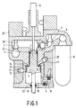
- Figure 1 shows the actuator in its first or rest position in which the engine valve is closed.
- the shaft 16 connects to a conventional internal combustion engine poppet valve (not shown).
- a ball valve 3 is opened by a solenoid the high pressure hydraulic fluid in the accumulator 8 quickly forces the ball valve 5 open and applies high pressure to the hydraulic subpiston 1.
- the high pressure causes the subpiston 1 and its interconnected piston 2 to move downwards.
- This subpiston is formed as the upper portion including the reduced diameter face of the power piston 2.
- These two pistons 1 and 2 may be physically formed from the same piece of material as a piston assembly, yet are isolated from one another by leakproof seals 19, 21 and 23.
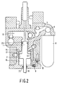
- Figure 4 illustrates the actuator just after the piston assembly has reached its lowest position.
- the very high pressure air in chamber 15 has displaced the piston 2 back slightly upwards to compress the fluid in chamber 18 to a pressure higher than the system pressure as supplied from the accumulator 8.
- Pressure in chamber 18 above the system pressure causes one-way valve 5 to re-close effectively latching the piston assembly and preventing any further rebound toward its initial or first position.
- Accumulator 8 is also being recharged while the piston assembly rests in the location of Figure 4 by way of hydraulic fluid inlet port 6.
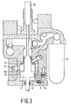
- Figure 5 shows the actuator with the piston assembly in its lower stable position. The difference between Figures 4 and 5 is that all valves are now closed and the fluid in chamber 18 is holding the piston assembly from any motion back upwards due to the very high pressure urging of the air in chamber 15. Also in Figure 5, the replenishing of the accumulator 8 fluid supply is nearly completed.
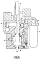
- Figure 7 illustrates the point in the piston assembly return trip where initial damping has been completed and the piston seal 19 has just closed off the port to orifice 12. Up to this point, damping of upward motion has been determined by the controlled egress of air from the chamber 17 through both apertures 11 and 12, but, since seal 19 has now covered the opening to aperture 12, the damping is increased and fluid now exits more slowly through aperture 11 only.
- the size of aperture 11 controls the final damping to assure gentle seating of the poppet valve as the actuator piston assembly reaches its starting or initial position as illustrated in Figure 1.
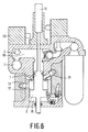
- Figure 8 illustrates in greater detail the dual stage controlled damping used to control the critical seating of the poppet valve.
- an air manifold 14 disposed about at least a substantial portion of the periphery of the cylinder which feeds air through a multi-vane reed valve 27. This allows entry of air into chamber 17 during downward movement of the piston assembly in a miner virtually free of any throttling retardation or losses.
- the reed valve closes and air must escape chamber 17 through the apertures 11 and 12.
- Adjustable needle valves 29 and 31 are located adjacent and movable into the orifices 11 and 12 for the precise adjustment of the size of these air escapement openings and therefore also of the initial and final damping respectively.
- the aperture 30 extends through the piston wall and communicates with chamber 17 when the piston 2 is in suitable positions such as shown, for example, in Figure 3.
- the screw or needle portion of needle valve 31 extends orthogonally to this aperture and seats in a conical seat 33.
- the separation between the end of the needle and the conical seat defines the size of the aperture and may be varied as the screw is moved in or out.
- many other types of adjustable apertures may be employed.
Landscapes
- Engineering & Computer Science (AREA)
- Mechanical Engineering (AREA)
- General Engineering & Computer Science (AREA)
- Valve Device For Special Equipments (AREA)
- Fluid-Pressure Circuits (AREA)
Claims (5)
- Mécanisme d'actionneur hydraulique bistable asymétrique comprenant :- une source de fluide hydraulique à haute pression réapprovisionnable (8) pour provoquer la translation d'une partie (1, 2) du mécanisme dans un sens à partir d'une position initiale;- une première chambre d'amortissement (15) dans laquelle de l'air est comprimé au cours de la translation de la partie de mécanisme (1, 2) dans ledit premier sens, la compression de l'air ralentissant la translation dans ledit premier sens de la partie de mécanisme (1, 2);
des moyens (4, 5, 25) pour empêcher momentanément une inversion du sens de translation de la partie de mécanisme (1, 2) lorsque la translation de la partie de mécanisme (1, 2) ralentit jusqu'à l'arrêt;- des moyens (25) susceptibles d'opérer sur commande pour désactiver les moyens d'empêchement momentané (4, 5, 25) de manière à libérer la partie de mécanisme (1, 2) et à la déplacer dans un sens opposé au premier sens sous l'influence de la pression de l'air comprimé dans la première chambre d'amortissement (15), et- une deuxième chambre d'amortissement (17) dans laquelle de l'air est comprimé au cours de la translation de la partie de mécanisme (1, 2) dans le sens opposé audit premier sens pour amortir et ralentir la translation de la partie de mécanisme (1, 2) lorsqu'elle revient vers la position initiale,
caractérisé en ce que le mécanisme comprend, en outre, une première ouverture réglable (12) permettant à de l'air de s'échapper de la deuxième chambre d'amortissement (17) pendant une partie du trajet de retour de la partie de mécanisme (1, 2) vers sa position initiale et une deuxième ouverture réglable (11) pour permettre à de l'air de s'échapper de la deuxième chambre d'amortissement (17) au cours du trajet de retour entier de la partie de mécanisme (1, 2) vers sa position initiale. - Mécanisme d'actionneur hydraulique bistable asymétrique selon la revendication 1, caractérisé en ce que la partie de mécanisme (1, 2) comprend un piston à mouvement de va-et-vient (1, 2) ayant une première, une deuxième et une troisième faces de travail qui définissent chacune une partie d'une première, d'une deuxième et d'une troisième chambres à volume variable correspondantes (15, 17, 18), dont les volumes varient linéairement avec la position du piston (1, 2), ladite première chambre d'amortissement (15) étant la première chambre, la deuxième chambre d'amortissement (17) étant la deuxième chambre et la troisième chambre (18) comprenant une partie des moyens (4, 5, 25) pour empêcher momentanément l'inversion de la partie de mécanisme (1, 2) et coopérant avec la source réapprovisionnable (8) de fluide hydraulique sous pression élevée peur provoquer la translation de la partie de mécanisme (1, 2).
- Mécanisme d'actionneur hydraulique bistable asymétrique selon la revendication 2, caractérisé en ce qu'il comprend, en outre, un premier clapet d'admission de fluide hydraulique sous pression élevée actionnable sélectivement (3) raccordant la troisième chambre (18) à la source (8) de fluide hydraulique sous pression élevée et un deuxième clapet d'évacuation de fluide hydraulique sous pression élevée actionnable sélectivement (4) raccordant la troisième chambre (18) à un retour de fluide hydraulique sous basse pression (7).
- Mécanisme d'actionneur hydraulique bistable asymétrique selon la revendication 3, caractérisé en ce que l'actionnement du premier clapet d'admission (3) amorce la translation du piston (1, 2) dans ledit premier sens, tandis que l'actionnement du deuxième clapet d'évacuation (4) désactive les moyens d'empêchement momentané (4, 5, 25) et amorce le retour du piston (1, 2) vers sa position initiale, le mécanisme comprenant, en outre, un deuxième clapet d'admission (9) pour fournir une pression d'air de verrouillage à la première chambre d'amortissement (15) au moins lorsque le piston (1, 2) est dans la position initiale pour verrouiller le piston (1, 2) dans la position initiale jusqu'à ce que la translation du piston (1, 2) soit amorcée par le premier clapet d'admission (3).
- Mécanisme de soupape à commande électronique comprenant une soupape d'admission ou d'échappement de moteur, propre à être utilisée dans un moteur à combustion interne et pourvue d'une longue tige de soupape (16), dans lequel la tige de soupape (16) peut se déplacer dans le sens de la longueur de la tige sous l'action d'un mécanisme d'actionneur hydraulique bistable asymétrique selon la revendication 1, 2, 3 ou 4, caractérisé en ce que la tige de soupape (16) est couplée à la partie de mécanisme (1, 2) et peut se déplacer dans le sens de la longueur de la tige à partir d'une position de fermeture de la soupape, dans laquelle la partie de mécanisme (1, 2) se trouve dans la position initiale, vers une position d'ouverture de la soupape, dans laquelle la partie de mécanisme (1, 2) est soumise à une translation dans ledit premier sens sous l'influence du fluide hydraulique sous pression élevée.
Applications Claiming Priority (2)
| Application Number | Priority Date | Filing Date | Title |
|---|---|---|---|
| US557369 | 1990-07-24 | ||
| US07/557,369 US5058538A (en) | 1990-07-24 | 1990-07-24 | Hydraulically propelled phneumatically returned valve actuator |
Publications (2)
| Publication Number | Publication Date |
|---|---|
| EP0468571A1 EP0468571A1 (fr) | 1992-01-29 |
| EP0468571B1 true EP0468571B1 (fr) | 1995-05-24 |
Family
ID=24225116
Family Applications (1)
| Application Number | Title | Priority Date | Filing Date |
|---|---|---|---|
| EP91201850A Expired - Lifetime EP0468571B1 (fr) | 1990-07-24 | 1991-07-15 | Vérin à commande hydraulique et retour pneumatique pour soupape |
Country Status (5)
| Country | Link |
|---|---|
| US (1) | US5058538A (fr) |
| EP (1) | EP0468571B1 (fr) |
| JP (1) | JPH04232319A (fr) |
| CA (1) | CA2047448A1 (fr) |
| DE (1) | DE69109951T2 (fr) |
Families Citing this family (23)
| Publication number | Priority date | Publication date | Assignee | Title |
|---|---|---|---|---|
| US5152260A (en) * | 1991-04-04 | 1992-10-06 | North American Philips Corporation | Highly efficient pneumatically powered hydraulically latched actuator |
| US5109812A (en) * | 1991-04-04 | 1992-05-05 | North American Philips Corporation | Pneumatic preloaded actuator |
| US5255641A (en) | 1991-06-24 | 1993-10-26 | Ford Motor Company | Variable engine valve control system |
| US5193495A (en) * | 1991-07-16 | 1993-03-16 | Southwest Research Institute | Internal combustion engine valve control device |
| DE69211942T2 (de) * | 1991-08-21 | 1996-10-31 | Honda Motor Co Ltd | Hubventilsteuerungsvorrichtung für Brennkraftmaschine |
| US5606940A (en) * | 1991-12-31 | 1997-03-04 | Caterpillar Inc. | Engine valve seating velocity hydraulic snubber |
| AU9136491A (en) * | 1991-12-31 | 1993-07-28 | Caterpillar Inc. | Engine valve seating velocity hydraulic snubber |
| US5224683A (en) * | 1992-03-10 | 1993-07-06 | North American Philips Corporation | Hydraulic actuator with hydraulic springs |
| US5253619A (en) * | 1992-12-09 | 1993-10-19 | North American Philips Corporation | Hydraulically powered actuator with pneumatic spring and hydraulic latching |
| US5647318A (en) | 1994-07-29 | 1997-07-15 | Caterpillar Inc. | Engine compression braking apparatus and method |
| US5540201A (en) | 1994-07-29 | 1996-07-30 | Caterpillar Inc. | Engine compression braking apparatus and method |
| US5526784A (en) | 1994-08-04 | 1996-06-18 | Caterpillar Inc. | Simultaneous exhaust valve opening braking system |
| WO1997009516A1 (fr) * | 1995-09-01 | 1997-03-13 | Serge Vallve | Ensemble soupape pneumatique pour moteur |
| DE19544473C2 (de) * | 1995-11-29 | 1999-04-01 | Daimler Benz Ag | Mechanisch-hydraulisch arbeitende Steuerung für ein Gaswechselventil einer Brennkraftmaschine |
| US6315265B1 (en) | 1999-04-14 | 2001-11-13 | Wisconsin Alumni Research Foundation | Variable valve timing actuator |
| DE10249452B4 (de) * | 2002-10-24 | 2009-10-15 | Man Diesel, Filial Af Man Diesel Se, Tyskland | Auslassventil |
| DE102006040671A1 (de) * | 2006-08-30 | 2008-03-06 | Schaeffler Kg | Drosselventil für eine Brennkraftmaschine mit elektrohydraulischer Ventilsteuerung |
| US7603858B2 (en) * | 2007-05-11 | 2009-10-20 | Lawrence Livermore National Security, Llc | Harmonic engine |
| AU2008284442B2 (en) * | 2007-08-07 | 2011-04-21 | Scuderi Group, Llc | Split-cycle engine with a helical crossover passage |
| DE102008054014A1 (de) * | 2008-10-30 | 2010-05-06 | Man Nutzfahrzeuge Aktiengesellschaft | Gaswechselventil für Brennkraftmaschinen |
| US8807012B1 (en) | 2010-08-30 | 2014-08-19 | Lawrence Livermore National Security, Llc | Harmonic engine |
| US9291056B2 (en) | 2010-08-30 | 2016-03-22 | Lawrence Livermore National Security, Llc | Harmonic uniflow engine |
| JP7811563B2 (ja) * | 2023-03-31 | 2026-02-05 | 株式会社三井E&S | 排気弁駆動装置 |
Family Cites Families (15)
| Publication number | Priority date | Publication date | Assignee | Title |
|---|---|---|---|---|
| US3537355A (en) * | 1966-12-14 | 1970-11-03 | George N Bliss | Fluid-operated servomechanism |
| US4206728A (en) * | 1978-05-01 | 1980-06-10 | General Motors Corporation | Hydraulic valve actuator system |
| US4759260A (en) * | 1978-05-17 | 1988-07-26 | Lew Yon S | Super reliable air-spring return air cylinder |
| DK225982A (da) * | 1981-07-07 | 1983-01-08 | Sulzer Ag | Indstroemnings-eller udstoedningsventil til en forbraendingsmotors cylindertopstykke |
| DE3139399A1 (de) * | 1981-09-30 | 1983-04-14 | Gebrüder Sulzer AG, 8401 Winterthur | Antrieb fuer ein schwingungsfaehiges system |
| SU1132034A1 (ru) * | 1983-02-23 | 1984-12-30 | Ворошиловградский машиностроительный институт | Устройство дл гидравлического привода клапанов газораспределени двигател внутреннего сгорани |
| US4555974A (en) * | 1983-09-02 | 1985-12-03 | Pneumo Corporation | Servo actuator control/damping mechanism and method |
| DK149514C (da) * | 1983-09-16 | 1986-12-22 | Danfoss As | Hydraulisk aktuator til styring af ventiler |
| SE459516B (sv) * | 1984-02-09 | 1989-07-10 | Bo Inge Gustav Jareke | Pneumatisk servoventil omfattande en i en cylinder foerskjutbar dubbelkolv |
| US4777800A (en) * | 1984-03-05 | 1988-10-18 | Vetco Gray Inc. | Static head charged hydraulic accumulator |
| US4889035A (en) * | 1985-07-16 | 1989-12-26 | Thermo Electron Web Systems, Inc. | Magnetically actuated valve for cyclically operating piston-cylinder actuator |
| US4836757A (en) * | 1987-02-13 | 1989-06-06 | Mechanical Technology Incorporated | Pressure actuated movable head for a resonant reciprocating compressor balance chamber |
| JPH0794845B2 (ja) * | 1987-02-24 | 1995-10-11 | 本田技研工業株式会社 | 差圧応動式アクチュエータ |
| US4922805A (en) * | 1988-09-14 | 1990-05-08 | Beswick Paul R | Fluid actuated cylinder |
| JP2664986B2 (ja) * | 1989-04-03 | 1997-10-22 | 三菱重工業株式会社 | 内燃機関の動弁装置 |
-
1990
- 1990-07-24 US US07/557,369 patent/US5058538A/en not_active Expired - Lifetime
-
1991
- 1991-07-15 EP EP91201850A patent/EP0468571B1/fr not_active Expired - Lifetime
- 1991-07-15 DE DE69109951T patent/DE69109951T2/de not_active Expired - Fee Related
- 1991-07-19 CA CA002047448A patent/CA2047448A1/fr not_active Abandoned
- 1991-07-24 JP JP3206206A patent/JPH04232319A/ja active Pending
Also Published As
| Publication number | Publication date |
|---|---|
| EP0468571A1 (fr) | 1992-01-29 |
| JPH04232319A (ja) | 1992-08-20 |
| CA2047448A1 (fr) | 1992-01-25 |
| DE69109951D1 (de) | 1995-06-29 |
| US5058538A (en) | 1991-10-22 |
| DE69109951T2 (de) | 1995-12-21 |
Similar Documents
| Publication | Publication Date | Title |
|---|---|---|
| EP0468571B1 (fr) | Vérin à commande hydraulique et retour pneumatique pour soupape | |
| US5152260A (en) | Highly efficient pneumatically powered hydraulically latched actuator | |
| US4831973A (en) | Repulsion actuated potential energy driven valve mechanism | |
| KR950014405B1 (ko) | 위치 및 자기 에너지 구동식 밸브장치 | |
| US5022358A (en) | Low energy hydraulic actuator | |
| US4852528A (en) | Pneumatic actuator with permanent magnet control valve latching | |
| US4878464A (en) | Pneumatic bistable electronic valve actuator | |
| US4974495A (en) | Electro-hydraulic valve actuator | |
| US4000756A (en) | High speed engine valve actuator | |
| EP0468548B1 (fr) | Vérin à retour par récupération d'énergie | |
| JP2645942B2 (ja) | 内燃機関の給排気バルブ制御方法及び装置 | |
| US5221072A (en) | Resilient hydraulic actuator | |
| US5125371A (en) | Spring driven hydraulic actuator | |
| US4870930A (en) | Engine valve control apparatus | |
| US4967702A (en) | Fast acting valve | |
| US4915015A (en) | Pneumatic actuator | |
| US5109812A (en) | Pneumatic preloaded actuator | |
| US4942852A (en) | Electro-pneumatic actuator | |
| US4899700A (en) | Pneumatically powered valve actuator | |
| US5003938A (en) | Pneumatically powered valve actuator | |
| EP0377251A1 (fr) | Actionneur de soupape compact | |
| EP1199446B1 (fr) | Méthode et dispositif pour commande de soupape dans un moteur à explosion | |
| WO1993001399A1 (fr) | Systeme de soupape de moteur a recuperation et son procede de fonctionnement | |
| JP2022511027A (ja) | 内燃機関内の弁アクチュエータを電気的に制御する方法及びデバイス | |
| EP3830398B1 (fr) | Poussoir à commande électrique pour un moteur à combustion interne |
Legal Events
| Date | Code | Title | Description |
|---|---|---|---|
| PUAI | Public reference made under article 153(3) epc to a published international application that has entered the european phase |
Free format text: ORIGINAL CODE: 0009012 |
|
| AK | Designated contracting states |
Kind code of ref document: A1 Designated state(s): DE FR GB IT SE |
|
| 17P | Request for examination filed |
Effective date: 19920724 |
|
| 17Q | First examination report despatched |
Effective date: 19930329 |
|
| GRAA | (expected) grant |
Free format text: ORIGINAL CODE: 0009210 |
|
| AK | Designated contracting states |
Kind code of ref document: B1 Designated state(s): DE FR GB IT SE |
|
| REF | Corresponds to: |
Ref document number: 69109951 Country of ref document: DE Date of ref document: 19950629 |
|
| ITF | It: translation for a ep patent filed | ||
| ET | Fr: translation filed | ||
| PLBE | No opposition filed within time limit |
Free format text: ORIGINAL CODE: 0009261 |
|
| STAA | Information on the status of an ep patent application or granted ep patent |
Free format text: STATUS: NO OPPOSITION FILED WITHIN TIME LIMIT |
|
| 26N | No opposition filed | ||
| REG | Reference to a national code |
Ref country code: GB Ref legal event code: 732E |
|
| REG | Reference to a national code |
Ref country code: FR Ref legal event code: TP |
|
| REG | Reference to a national code |
Ref country code: GB Ref legal event code: IF02 |
|
| PGFP | Annual fee paid to national office [announced via postgrant information from national office to epo] |
Ref country code: GB Payment date: 20020711 Year of fee payment: 12 |
|
| PGFP | Annual fee paid to national office [announced via postgrant information from national office to epo] |
Ref country code: SE Payment date: 20020724 Year of fee payment: 12 |
|
| PGFP | Annual fee paid to national office [announced via postgrant information from national office to epo] |
Ref country code: FR Payment date: 20020726 Year of fee payment: 12 |
|
| PGFP | Annual fee paid to national office [announced via postgrant information from national office to epo] |
Ref country code: DE Payment date: 20020916 Year of fee payment: 12 |
|
| PG25 | Lapsed in a contracting state [announced via postgrant information from national office to epo] |
Ref country code: GB Free format text: LAPSE BECAUSE OF NON-PAYMENT OF DUE FEES Effective date: 20030715 |
|
| PG25 | Lapsed in a contracting state [announced via postgrant information from national office to epo] |
Ref country code: SE Free format text: LAPSE BECAUSE OF NON-PAYMENT OF DUE FEES Effective date: 20030716 |
|
| PG25 | Lapsed in a contracting state [announced via postgrant information from national office to epo] |
Ref country code: DE Free format text: LAPSE BECAUSE OF NON-PAYMENT OF DUE FEES Effective date: 20040203 |
|
| EUG | Se: european patent has lapsed | ||
| GBPC | Gb: european patent ceased through non-payment of renewal fee |
Effective date: 20030715 |
|
| PG25 | Lapsed in a contracting state [announced via postgrant information from national office to epo] |
Ref country code: FR Free format text: LAPSE BECAUSE OF NON-PAYMENT OF DUE FEES Effective date: 20040331 |
|
| REG | Reference to a national code |
Ref country code: FR Ref legal event code: ST |
|
| PG25 | Lapsed in a contracting state [announced via postgrant information from national office to epo] |
Ref country code: IT Free format text: LAPSE BECAUSE OF NON-PAYMENT OF DUE FEES Effective date: 20050715 |