EP0468620B1 - Antenne à double bande avec réutilisation des fréquences - Google Patents
Antenne à double bande avec réutilisation des fréquences Download PDFInfo
- Publication number
- EP0468620B1 EP0468620B1 EP91303892A EP91303892A EP0468620B1 EP 0468620 B1 EP0468620 B1 EP 0468620B1 EP 91303892 A EP91303892 A EP 91303892A EP 91303892 A EP91303892 A EP 91303892A EP 0468620 B1 EP0468620 B1 EP 0468620B1
- Authority
- EP
- European Patent Office
- Prior art keywords
- meanderline
- traces
- layers
- antenna
- waveguide
- Prior art date
- Legal status (The legal status is an assumption and is not a legal conclusion. Google has not performed a legal analysis and makes no representation as to the accuracy of the status listed.)
- Expired - Lifetime
Links
Images


Classifications
-
- H—ELECTRICITY
- H01—ELECTRIC ELEMENTS
- H01Q—ANTENNAS, i.e. RADIO AERIALS
- H01Q21/00—Antenna arrays or systems
- H01Q21/24—Combinations of antenna units polarised in different directions for transmitting or receiving circularly and elliptically polarised waves or waves linearly polarised in any direction
- H01Q21/245—Combinations of antenna units polarised in different directions for transmitting or receiving circularly and elliptically polarised waves or waves linearly polarised in any direction provided with means for varying the polarisation
-
- H—ELECTRICITY
- H01—ELECTRIC ELEMENTS
- H01Q—ANTENNAS, i.e. RADIO AERIALS
- H01Q15/00—Devices for reflection, refraction, diffraction or polarisation of waves radiated from an antenna, e.g. quasi-optical devices
- H01Q15/24—Polarising devices; Polarisation filters
- H01Q15/242—Polarisation converters
- H01Q15/244—Polarisation converters converting a linear polarised wave into a circular polarised wave
Definitions
- This invention relates to antennas having frequency reuse capabilities, and more particularly to antennas having a four port network or quadruplexer located in the antenna waveguide, a feed horn attached to the waveguide, and a polarizer disposed at the aperture of the antenna for converting linearly polarized signals to circularly polarized signals.
- This device includes two coaxial waveguides, the outer waveguide being used for the transmission and reception of the four GHz band and the inner coaxial waveguide being utilized for the six GHz band.
- a tunable configuration of screws and baffles within the waveguides are utilized to convert the linearly polarized signals into circularly polarized signals.
- the device utilizes a grooved conical horn to transmit and receive signals.
- a meanderline polarizer comprising several printed-circuit sheets each covered with an array of conductive meander lines is disclosed in a paper entitled "Polarization Converters for a DBS Flat-Plate Antenna" published as BBC Research Department Report, No. 7, July 1988. As the title of the paper suggests, the meanderline polarizer was used only for a flat-plate antenna and no other investigations were made or uses contemplated.
- Japanese Patent Application No. A-1126803 disclosed the use of an antenna comprising a waveguide section coupled to a horn provided with a cover in the form of a meanderline polarizer.
- the waveguide section is provided with two orthogonal ports with one being axially positioned in order to input a linearly polarized signal into the antenna.
- the present invention provides a frequency reuse antenna comprising: a waveguide network having ports for transmitting and receiving orthogonal, linearly polarized signals of a second frequency; a feed horn being engaged to said waveguide network and adapted to enhance the transmission and reception of signals from and to said waveguide network respectively; and a signal polarizing means being engaged to the aperture of said feed horn and adapted to convert between linearly polarized signals and circularly polarized signals, characterised in that the antenna is a dual band antenna with the waveguide network having a central section and four ports, two of the ports being positioned to feed into the free end of the central section for receiving orthogonal, linearly polarized signals within a first-frequency band, and the other two of the ports being spaced apart at different axial positions along the central section near the end of the section to which the feed horn is attached whereby to transmit orthogonal linearly polarized signals within a second frequency band different to said first frequency band.
- the meanderline polarizer (16) preferably includes five separated layers of meanderlines, wherein the first and fifth layers (50 and 58 respectively) include identical meanderlines, the second and fourth (52 and 56 respectively) layers include identical meanderlines that differ from those of the first and fifth layers, and the third layer (54) includes meanderlines that differ from the others in the first, second, fourth and fifth layers. It is an advantage of the present invention that it provides a dual band frequency reuse antenna having minimal cross-polarization.
- the four port waveguide network is preferably constructed as a square waveguide, a pyramidal horn and meanderline polarizer to achieve increased signal gain and reduced cross-polarization. This provides dimensional stability over a broad thermal range, whereby the antenna is usable in an earth orbital environment.
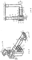
- the antenna 10 includes three main components, a waveguide 12, a horn 14 and a meanderline polarizer 16 that is attached to the aperture 17 of the horn 14.
- the antenna 10 is preferably designed to be used with a parabolic reflector 18, such that the antenna 10 is fixedly mounted to a structure (not shown) and the antenna beam is scanned by movement of the reflector 18 relative to the fixedly mounted antenna 10.
- the waveguide 12 includes a four port waveguide network.
- Two of the ports 20 and 22 are designed for the transmission of orthogonal, linearly polarized signals of a first frequency, which in the preferred embodiment is a 4.035 to 4.200 GHz transmission band frequency.
- the other two ports 24 and 26 are designed for the reception of orthogonal, linearly polarized signals of a different frequency, which in the preferred embodiment is a 6.260 to 6.425 GHz receiving band frequency.
- the four independent, linearly polarized signals (1 from each port) are coupled into the common square waveguide 12, which in turn excites the pyramidal feed horn 14.
- the meanderline polarizer 16 then converts the linearly polarized signals to circular polarizations, such that two oppositely, circularly polarized fields are radiated from the antenna 10 at the transmission band frequency.
- the meanderline polarizer also converts two oppositely, circularly polarized signals to two orthogonal, linearly polarized signals at the receiving band frequency.
- Each port 20, 22, 24 and 26 of the four port waveguide network includes an attachment flange 30, 32, 34 and 36 respectively, disposed about its outer end to which signal transmitting or receiving devices (not shown) are coupled.
- the orthogonal ports 24 and 26 feed directly into the side and throat respectively of the waveguide 12, whereas orthogonal ports 20 and 22 are provided with additional waveguide structures 40 and 42 respectively which lead to the body of the waveguide 12.
- the waveguide structures 40 and 42 comprise a series of rectangular corrugations formed perpendicularly to the central axis of the waveguide structures 40 and 42.
- support straps 46 are engaged across the outer surface of the corrugations to provide structural rigidity to the waveguide structures 40 and 42.
- the corrugated waveguide structures 40 and 42 are dimensionally configured to act as a short circuit to the six GHz signals while allowing the four GHz signals to pass therethrough.
- the linearly polarized six GHz receiving signal does not propagate into waveguide structures 40 and 42, but rather continues through the body of the waveguide 12 to the ports 24 and 26.
- a central section 48 of the waveguide 12 located behind ports 20 and 22 is dimensionally sized to prevent the propagation of the four GHz transmission signals backwards through the waveguide 12 to the six GHz ports 24 and 26.
- the feed horn 14 is a pyramidal horn having a flare angle of approximately 10 degrees and a square aperture having a side measurement of approximately 6 inches; its aperture 17 is located approximately 3.5 inches towards the reflector 18 from the focal point 50 of the reflector 18.
- the meanderline polarizer is oriented relative to the square aperture 17 of the feed horn 14, such that the meanderlines run diagonally across the aperture 17 of the feed horn 14.
- the improved meanderline polarizer 16 serves to transform the linearly polarized signals into circularly polarized signals at the aperture 17 of the antenna horn 14.
- the signals that propagate within the horn 14 and waveguide 12 are entirely orthogonal, linearly polarized signals, and no circularly polarized signals propagate within the horn 14 or waveguide 12. This configuration results in the transmission and reception within the waveguide of orthogonal, linearly polarized signals with significantly reduced cross-polarization, whereby improved signal gain and reduced noise is achieved.
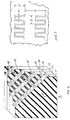
- the meanderline polarizer 16 is a sandwich structure including five thin layers 50, 52, 54, 56 and 58, each having a plurality of meanderline traces 60, 62, 64, 66 and 68, respectively, formed thereon.
- Four foam-like spacers 70, 72, 74 and 76 serve to separate the five meanderline layers.
- the use of meanderline polarizers that are generally configured as described hereinabove is well known in the art, as particularly taught in U.S. Patent 3,754,271 issued to J. Epis on August 21, 1973.
- a significant difference between the polarizer 16 of the present invention and the prior art polarizers resides in the utilization of meanderline traces of differing dimensions in the various layers 50, 52, 54, 56 and 58.
- the meanderline traces in layers 50 and 58 are identical
- the meanderline traces in layers 52 and 56 are identical, although differing in dimensions from the meanderline traces in layers 50 and 58.
- the meanderline traces in layer 54 are different in dimension from those of any other layer.
- the polarizer is a 9.0 ⁇ square by 2.0 ⁇ thick sandwich construction.
- the sandwich consists of the four spacers 60, 62, 64 and 66 composed of Stanthyne 817 Foam, and the five layers 50, 52, 54, 56 and 58 are composed of etched 1/2 oz. copper clad 3 mill Kapton bonded together with Hysol 9309 adhesive. Bonding is done so as not to cover the traces.
- the polarizer is bonded to a fiberglass frame 19 which is bolted to the aperture 17 of the horn 14.
- the traces are preferably formed on the Kapton layers utilizing printed circuit board techniques to provide close tolerances and reliability to the device.
- the dimensions of the meanderline traces in each layer can be expressed by four parameters that are designated as: A, the periodicity of a meanderline trace; H, the height of the meanderline trace; W, the width of the meanderline trace; and B, the distance between adjacent meanderline traces.
- A the periodicity of a meanderline trace
- H the height of the meanderline trace
- W the width of the meanderline trace
- B the distance between adjacent meanderline traces.
- the following table provides the dimensions for each of the layers of the meanderline polarizer 16.
- the present invention provides a reuse frequency capability. That is, that the same frequency can be used for transmitting two signals, one of which is circularly polarized in a first sense and the other of which is circularly polarized in an opposite sense. Additionally, the utilization of four ports in the waveguide network permits the simultaneous utilization of two reuse frequency signals, approximately 4 GHz and approximately 6 GHz.
- the use of a meanderline polarizer at the aperture 17 of the feed horn 14 provides improved performance as compared to prior art devices which attempt to convert signals from circular polarization to linear polarization within the waveguide.
- the improved meanderline polarizer reduces cross-polarization and thus contributes to the improved performance of the invention.
Landscapes
- Waveguide Aerials (AREA)
- Control Of Motors That Do Not Use Commutators (AREA)
- Waveguide Switches, Polarizers, And Phase Shifters (AREA)
- Aerials With Secondary Devices (AREA)
Claims (8)
- Antenne à réutilisation de fréquence comprenant :- un réseau de guide d'onde (12) possédant des connecteurs pour émettre et recevoir des signaux normaux polarisés, de façon linéaire, d'une seconde fréquence;- un cornet d'alimentation (14) coopérant avec ledit réseau de guide d'onde (12) et prévu pour améliorer respectivement l'émission et la réception des signaux à partir et vers ledit réseau de guide d'onde (12); et- un moyen de polarisation de signal (16) coopérant avec l'ouverture (17) dudit cornet d'alimentation (14) et prévu pour une conversion entre les signaux polarisés, de façon linéaire, et des signaux polarisés de façon circulaire;antenne caractérisée en ce que l'antenne est une antenne à double bande, le réseau de guide d'onde (12) possédant une section centrale et quatre connecteurs (20, 22, 24, 26), deux des connecteurs (24, 26) étant placés pour alimenter l'extrémité libre de la section centrale pour la réception de signaux normaux polarisés, de façon linéaire, dans une première bande de fréquences, et les deux autres connecteurs (20, 22) étant espacés sur différentes positions axiales le long de la section centrale près de l'extrémité de la section sur laquelle est fixé le cornet d'alimentation (14) afin d'émettre des signaux normaux polarisés, de façon linéaire, dans une seconde bande de fréquences, différente de ladite première bande de fréquences.
- Antenne à réutilisation de fréquence de double bande selon la revendication 1, dans laquelle ledit moyen de signal (16) comprend un polariseur à lignes en dents de scie.
- Antenne à réutilisation de fréquence de double bande selon la revendication 2, dans laquelle ledit polariseur à lignes en dents de scie comprend une pluralité de couches (50, 52, 54, 56, 58), chacune desdites couches comprenant une pluralité de marques de lignes en dents de scie pratiquement identiques (60, 62, 64, 66, 68) formées dessus.
- Antenne à réutilisation de fréquence de double bande selon la revendication 3, dans laquelle les marques de lignes en dents de scie (60, 62) formées sur au moins deux couches (50, 52) desdits couches présentent des dimensions différentes.
- Antenne à réutilisation de fréquence de double bande selon la revendication 4, dans laquelle lesdites marques de lignes en dents de scie (60) formées sur une première couche (50) sont de dimensions différentes desdites marques de lignes en dents de scie (62) formées sur une seconde couche et lesdites marques de lignes en dents de scie (64) formées sur une troisième couche (54) sont de dimensions différentes desdits marques de lignes en dents de scie (60, 62) formées sur chacune desdites première (50) et seconde (52) couches.
- Antenne à réutilisation de fréquence de double bande selon la revendication 3, dans laquelle ledit polariseur à lignes en dents de scie comprend cinq couches (50, 52, 54, 56, 58), chacune desdites couches possédant une pluralité de marques de lignes en dents de scie (60, 62, 64, 66, 68) formées dessus;
lesdites marques de lignes en dents de scie formées sur lesdites première et cinquième couches (50, 58) étant de dimensions pratiquement identiques;
lesdites marques de lignes en dents de scie formées sur lesdites seconde et quatrième couches (52, 56) étant de dimensions pratiquement identiques, lesdites marques de lignes en dents de scie formées sur lesdites seconde et quatrième couches étant de dimensions différentes desdites marques de lignes en dents de scie formées sur lesdites première et cinquième couches; et
lesdites marques de lignes en dents de scie formées sur ladite troisième couche (54) étant de dimensions différentes desdites marques de lignes en dents de scie formées sur lesdites première, seconde, quatrième et cinquième couches. - Antenne à réutilisation de fréquence de double bande selon l'une quelconque des revendications précédentes, dans laquelle la section centrale du réseau de guide d'onde (12) et le cornet (14) ont des sections droites pratiquement carrées.
- Antenne à réutilisation de fréquence de double bande selon l'une quelconque des revendications précédentes, comprenant, de plus, des première et seconde structures de guide d'onde ondulées (40, 42) possédant chacune un axe central et des ondulations formées perpendiculairement à l'axe central correspondant pour des signaux de court-circuit de la première bande de fréquences tout en permettant le passage des signaux de la seconde bande de fréquences, lesdites structures ondulées de guide d'onde (40, 42) étant couplées entre lesdites sections centrales et lesdites deux autres parties (20, 22) du réseau de guide d'onde.
Applications Claiming Priority (2)
| Application Number | Priority Date | Filing Date | Title |
|---|---|---|---|
| US55903490A | 1990-07-26 | 1990-07-26 | |
| US559034 | 1990-07-26 |
Publications (3)
| Publication Number | Publication Date |
|---|---|
| EP0468620A2 EP0468620A2 (fr) | 1992-01-29 |
| EP0468620A3 EP0468620A3 (en) | 1992-05-20 |
| EP0468620B1 true EP0468620B1 (fr) | 1995-12-27 |
Family
ID=24232016
Family Applications (1)
| Application Number | Title | Priority Date | Filing Date |
|---|---|---|---|
| EP91303892A Expired - Lifetime EP0468620B1 (fr) | 1990-07-26 | 1991-04-30 | Antenne à double bande avec réutilisation des fréquences |
Country Status (4)
| Country | Link |
|---|---|
| EP (1) | EP0468620B1 (fr) |
| JP (1) | JP2651962B2 (fr) |
| CA (2) | CA2041572C (fr) |
| DE (1) | DE69115783T2 (fr) |
Families Citing this family (5)
| Publication number | Priority date | Publication date | Assignee | Title |
|---|---|---|---|---|
| JPH08139502A (ja) * | 1994-11-14 | 1996-05-31 | Nec Corp | 円偏波発生器 |
| KR20090095518A (ko) * | 2008-03-05 | 2009-09-09 | (주)인텔리안테크놀로지스 | 반사경 안테나 및 혼 안테나를 이용한 다중 대역 신호 송/수신 장치 및 그 방법 |
| CN107093802B (zh) * | 2017-03-20 | 2019-07-23 | 东南大学 | 口径面相位和幅度均匀分布的高增益透镜天线 |
| US10665931B2 (en) | 2017-08-01 | 2020-05-26 | Lockheed Martin Corporation | Waveguide aperture design for geo satellites |
| CN114709622B (zh) * | 2022-03-31 | 2024-04-23 | 重庆邮电大学 | 一种基于超表面结构的极化单元、极化转换器和制备方法 |
Family Cites Families (7)
| Publication number | Priority date | Publication date | Assignee | Title |
|---|---|---|---|---|
| US3754271A (en) * | 1972-07-03 | 1973-08-21 | Gte Sylvania Inc | Broadband antenna polarizer |
| DE3023562C2 (de) * | 1980-06-24 | 1982-10-28 | Siemens AG, 1000 Berlin und 8000 München | Einrichtung zur Polarisationsumwandlung elektromagnetischer Wellen |
| FR2488055A1 (fr) * | 1980-07-31 | 1982-02-05 | Thomson Csf | Transducteur d'antenne pour antenne d'emission-reception et source primaire d'antenne equipee d'un tel transducteur |
| FR2529392B1 (fr) * | 1982-06-25 | 1985-06-28 | Thomson Csf | Dispositif de multiplexage pour grouper deux bandes de frequences et multiplexeur comportant un tel dispositif |
| JPS60176302A (ja) * | 1984-02-22 | 1985-09-10 | Mitsubishi Electric Corp | 偏分波器 |
| JPH0611085B2 (ja) * | 1987-02-23 | 1994-02-09 | 三菱電機株式会社 | 円偏波アレ−アンテナ |
| JPH01126803A (ja) * | 1987-11-12 | 1989-05-18 | Mitsubishi Electric Corp | ホーンアンテナ装置 |
-
1991
- 1991-04-30 DE DE69115783T patent/DE69115783T2/de not_active Expired - Fee Related
- 1991-04-30 EP EP91303892A patent/EP0468620B1/fr not_active Expired - Lifetime
- 1991-05-01 CA CA002041572A patent/CA2041572C/fr not_active Expired - Fee Related
- 1991-07-05 JP JP3191142A patent/JP2651962B2/ja not_active Expired - Lifetime
- 1991-07-12 CA CA2046975A patent/CA2046975A1/en active Pending
Also Published As
| Publication number | Publication date |
|---|---|
| JP2651962B2 (ja) | 1997-09-10 |
| CA2041572A1 (fr) | 1992-01-27 |
| CA2046975A1 (en) | 1992-01-27 |
| EP0468620A3 (en) | 1992-05-20 |
| DE69115783T2 (de) | 1996-07-25 |
| EP0468620A2 (fr) | 1992-01-29 |
| CA2041572C (fr) | 1999-11-09 |
| DE69115783D1 (de) | 1996-02-08 |
| JPH05136624A (ja) | 1993-06-01 |
Similar Documents
| Publication | Publication Date | Title |
|---|---|---|
| US5258768A (en) | Dual band frequency reuse antenna | |
| US5596336A (en) | Low profile TEM mode slot array antenna | |
| JP3029231B2 (ja) | 二重円形偏波temモードのスロットアレーアンテナ | |
| JP2733472B2 (ja) | 導波管スロット・アンテナ及びその製造方法並びに導波管の結合構造 | |
| US5872545A (en) | Planar microwave receive and/or transmit array antenna and application thereof to reception from geostationary television satellites | |
| US6452560B2 (en) | Slot array antenna with reduced edge diffraction | |
| AU603103B2 (en) | Microwave antenna | |
| US4263598A (en) | Dual polarized image antenna | |
| US5223848A (en) | Duplexing circularly polarized composite | |
| US5793330A (en) | Interleaved planar array antenna system providing opposite circular polarizations | |
| JPH07176950A (ja) | 衛星通信用アンテナ | |
| CA2041572C (fr) | Antenne double bande a double utilisation des frequences | |
| SK70096A3 (en) | Planar antenna | |
| JPH0590826A (ja) | マイクロストリツプアンテナ | |
| US5233361A (en) | Planar high-frequency aerial for circular polarization | |
| CN115441167A (zh) | 集成有双工器的紧凑型低剖面开孔天线 | |
| JPH06125214A (ja) | 平面アンテナ | |
| JPH09172323A (ja) | 平面アンテナ | |
| JPH07120893B2 (ja) | 平面アンテナ | |
| KR100429684B1 (ko) | 편파 선택형 평면 안테나 | |
| JPH0437204A (ja) | 平面アンテナ | |
| JPS61205006A (ja) | 円偏波アンテナ | |
| JPS61102802A (ja) | 偏分波器 | |
| JPH0715233A (ja) | 平面アンテナ | |
| JPH07122928A (ja) | マイクロストリップスロットアンテナ |
Legal Events
| Date | Code | Title | Description |
|---|---|---|---|
| PUAI | Public reference made under article 153(3) epc to a published international application that has entered the european phase |
Free format text: ORIGINAL CODE: 0009012 |
|
| AK | Designated contracting states |
Kind code of ref document: A2 Designated state(s): DE FR GB IT |
|
| PUAL | Search report despatched |
Free format text: ORIGINAL CODE: 0009013 |
|
| AK | Designated contracting states |
Kind code of ref document: A3 Designated state(s): DE FR GB IT |
|
| RIN1 | Information on inventor provided before grant (corrected) |
Inventor name: SMITH, TERRY M. |
|
| 17P | Request for examination filed |
Effective date: 19921120 |
|
| 17Q | First examination report despatched |
Effective date: 19940607 |
|
| GRAA | (expected) grant |
Free format text: ORIGINAL CODE: 0009210 |
|
| AK | Designated contracting states |
Kind code of ref document: B1 Designated state(s): DE FR GB IT |
|
| ITF | It: translation for a ep patent filed | ||
| REF | Corresponds to: |
Ref document number: 69115783 Country of ref document: DE Date of ref document: 19960208 |
|
| ET | Fr: translation filed | ||
| PLBE | No opposition filed within time limit |
Free format text: ORIGINAL CODE: 0009261 |
|
| STAA | Information on the status of an ep patent application or granted ep patent |
Free format text: STATUS: NO OPPOSITION FILED WITHIN TIME LIMIT |
|
| 26N | No opposition filed | ||
| REG | Reference to a national code |
Ref country code: GB Ref legal event code: IF02 |
|
| PGFP | Annual fee paid to national office [announced via postgrant information from national office to epo] |
Ref country code: FR Payment date: 20020401 Year of fee payment: 12 |
|
| PGFP | Annual fee paid to national office [announced via postgrant information from national office to epo] |
Ref country code: DE Payment date: 20020418 Year of fee payment: 12 |
|
| PGFP | Annual fee paid to national office [announced via postgrant information from national office to epo] |
Ref country code: GB Payment date: 20020424 Year of fee payment: 12 |
|
| PG25 | Lapsed in a contracting state [announced via postgrant information from national office to epo] |
Ref country code: GB Free format text: LAPSE BECAUSE OF NON-PAYMENT OF DUE FEES Effective date: 20030430 |
|
| PG25 | Lapsed in a contracting state [announced via postgrant information from national office to epo] |
Ref country code: DE Free format text: LAPSE BECAUSE OF NON-PAYMENT OF DUE FEES Effective date: 20031101 |
|
| GBPC | Gb: european patent ceased through non-payment of renewal fee | ||
| PG25 | Lapsed in a contracting state [announced via postgrant information from national office to epo] |
Ref country code: FR Free format text: LAPSE BECAUSE OF NON-PAYMENT OF DUE FEES Effective date: 20031231 |
|
| REG | Reference to a national code |
Ref country code: FR Ref legal event code: ST |
|
| PG25 | Lapsed in a contracting state [announced via postgrant information from national office to epo] |
Ref country code: IT Free format text: LAPSE BECAUSE OF NON-PAYMENT OF DUE FEES Effective date: 20050430 |