EP0468622A2 - Commutateur à résistance variable - Google Patents
Commutateur à résistance variable Download PDFInfo
- Publication number
- EP0468622A2 EP0468622A2 EP91304462A EP91304462A EP0468622A2 EP 0468622 A2 EP0468622 A2 EP 0468622A2 EP 91304462 A EP91304462 A EP 91304462A EP 91304462 A EP91304462 A EP 91304462A EP 0468622 A2 EP0468622 A2 EP 0468622A2
- Authority
- EP
- European Patent Office
- Prior art keywords
- actuator
- switch
- resistance
- terminal
- housing
- Prior art date
- Legal status (The legal status is an assumption and is not a legal conclusion. Google has not performed a legal analysis and makes no representation as to the accuracy of the status listed.)
- Granted
Links
Images
Classifications
-
- H—ELECTRICITY
- H01—ELECTRIC ELEMENTS
- H01H—ELECTRIC SWITCHES; RELAYS; SELECTORS; EMERGENCY PROTECTIVE DEVICES
- H01H9/00—Details of switching devices, not covered by groups H01H1/00 - H01H7/00
- H01H9/02—Bases, casings, or covers
- H01H9/06—Casing of switch constituted by a handle serving a purpose other than the actuation of the switch, e.g. by the handle of a vacuum cleaner
- H01H9/061—Casing of switch constituted by a handle serving a purpose other than the actuation of the switch, e.g. by the handle of a vacuum cleaner enclosing a continuously variable impedance
-
- H—ELECTRICITY
- H01—ELECTRIC ELEMENTS
- H01H—ELECTRIC SWITCHES; RELAYS; SELECTORS; EMERGENCY PROTECTIVE DEVICES
- H01H19/00—Switches operated by an operating part which is rotatable about a longitudinal axis thereof and which is acted upon directly by a solid body external to the switch, e.g. by a hand
- H01H19/54—Switches operated by an operating part which is rotatable about a longitudinal axis thereof and which is acted upon directly by a solid body external to the switch, e.g. by a hand the operating part having at least five or an unspecified number of operative positions
- H01H19/60—Angularly-movable actuating part carrying no contacts
- H01H19/635—Contacts actuated by rectilinearly-movable member linked to operating part, e.g. by pin and slot
Definitions
- This invention relates to switches,and more particularly to variable resistance switches for controlling the speed of electric motors.
- Portable tools having variable speed motors generally include switches for completing a motor energizing circuit and means for controlling the flow of energy to the motor. It is desirable to provide such tools with operating means for completing the energizing circuit and controlling the motor speed through the application of a continuous constant force.
- Another object of the invention is to provide a switch for energizing and controlling a small motor wherein the operating sequence is accomplished by the application of a continuous, constant force.
- a further object of the invention is to provide a switch for small motors wherein operation is initiated by the sequential closure of contacts and wherein resistance in the motor control circuit is varied thereafter.
- the invention comprises a switch including first and second switch means, actuator means operable in a first direction for sequentially closing the first and second switch means, respectively, and biasing means engaging the actuator means for urging the actuator means for movement in the opposite direction for opening the first and second switch means.
- Resistance means is disposed adjacent one of the switch means and is connected to a terminal means.
- the actuator means electrically couples the resistance means to one of the switch means wherein the actuator means is operative to vary the resistance between the one switch means and the terminal upon movement of the actuator means in the first direction and for increasing the resistance thereof upon return movement in the opposite direction.
- the invention also comprises the combination of a motor, a variable speed control and a switch for connecting the motor to a source of electrical energy.
- the switch includes first and second pairs of terminals, one terminal of each pair being adapted to be connected to the source of electrical energy.
- First and second switch means are connected in circuit between the terminals of each pair of terminals, respectively, and the motor is connected to the second terminal of the first pair of terminals.
- Control means is connected between the motor and the second terminal of the other pair of terminals.
- Actuator means is operable in a first direction for sequentially closing the first and second switch means, respectively, and biasing means engages the actuator means for urging the actuator means for movement in the opposite direction for opening the first and second switch means.
- Resistance means is disposed adjacent to one of the switch means and is connected to additional terminal means which couples the resistance means to the control means.
- the actuator means electrically couples the resistance means to one of the switch means and is operative to vary the resistance between the one switch means and the terminal means upon movement of the actuator means in the first direction and for increasing the resistance thereof upon return movement in the opposite direction whereby the resistance between the switch means and the control means is varied for varying the speed of the motor when the switch means are closed.
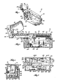
- the switch 10 includes a housing 12 and a cover 14. Disposed within housing 12 and beneath cover 14 is an actuator 16 which is movable longitudinally within housing 12 under the influence of a trigger 18 and a return spring 20. Also disposed within housing 12 are a pair of spring contact arms 22 and 24 and a pair of stationary contacts 26 and 28.
- the actuator 16 carries a conductive wiper 30 which is movable over a resistance strip 32 mounted on the inner bottom surface of the housing 12. As will be discussed more fully hereinbelow, movement of the actuator a first incremental distance under the influence of the trigger 18 will move the first switch arm 24 into engagement with contact 28 to complete a circuit between terminals 38 and 40.
- the housing 12, the cover 14 and the actuator 16 may be formed of any suitable nonconductive material.
- the housing 12 and the cover 14 may be formed of a polycarbonate and the actuator 16 of a nonconductive plastic.
- the housing 12 is generally rectangular in plan view and has a pair of side walls 42 and a center section 43 which includes a pair of end barriers 44 and 46 which extend upwardly between the terminals 34, 38 and 36, 40, respectively, for providing electrical insulation.
- a lower guide wall 48 extending longitudinally through housing 12 and adjacent the resistance strip 32 for isolating the same from the terminals 38 and 40 and for providing a guide for the actuator 16.
- the terminal 41 has an inverted U-shape and is suitably mounted at one end of housing 12 with one leg engaging an end of resistor strip 32 and a second end extending into a recess 50 formed in the base of housing 12 for receiving a conductor clip (not shown).
- the cover 14 is generally coextensive with the housing 12 and includes a top wall 54 and a pair of downwardly extending side walls 56 which embrace the side walls 42 of housing 12 and are fixed thereto in any suitable manner.
- a trigger support and guide 58 is formed integrally at and extends forwardly from one end of cover 14.
- Guide 58 is elongate and has an inverted U-shape in vertical section.
- a trigger support 60 is provided at the front end of guide 58 and extends generally upwardly therefrom.
- the trigger 18 also has an inverted U-shape in transverse section and includes sides 62 which extend downwardly along the opposite sides of guide 58.
- a pair of pivots 64 extend laterally from support 60 and through complementary openings in the sides 62 of trigger 18.
- the actuator 16 includes a body portion 66 and a stem 68 extending forwardly therefrom and through an opening 70 in the front of cover 14.
- the stem 68 also extends in parallelism with guide 58 and between its opposite sides.
- the free end of stem 68 is enlarged for receiving a transverse pin 71 which also extends through aligned openings in the lower ends of the sides 62 of trigger 18.
- a suitable seal such as a felt gasket 72, may be provided around the stem 68 and is received in grooves 73 and 74 in the housing portion 44 and the guide 58, respectively, for inhibiting the entry of foreign material into housing 12.
- a suitable seal such as a felt gasket 75, may also be provided between the housing 12 and the cover 14.
- An elongate recess 76 is formed in the upper end of the body portion 66 for receiving a return spring 20. It can be seen in FIGURE 1 that one end of spring 20 bears against the end of recess 76 and the other end abuts against a projection 78 extending downwardly from cover 14.
- a second guide 80 extends downwardly from the lower end of actuator 16 and bears against the guide wall 48 whereby the actuator is guided for longitudinal movement within housing 12 under the influence of the trigger 18 and the return spring 76.
- the terminals 34, 36, 38 and 40 each include first portions 34.1, 36.1, 38.1 and 40.1, respectively, having a generally inverted U-shape located generally at the corners of housing 12 and a planer strip 34.2, 36.2, 38.2 and 40.2, respectively, which extends along the inner bottom surface of housing 12. Partitions 82 separate the adjacent ends of terminal portions 34.2-36.2 and 38.2-40.2. Flexible contact arms 22 and 24 are connected respectively to terminals 36 and 38 and the stationary contacts 26 and 28 are respectively connected to terminals 34 and 40.
- the resistance strip 32 is applied to the surface of the housing 12 adjacent to and in general parallelism with the terminal portion 34.2. However, the two are electrically isolated except for the wiper 30 as will be discussed below. While any well-known resistance strip material may be employed, one such material is disclosed in United States Patent 4,771,263, issued September 13, 1988, and which is hereby incorporated by reference.
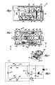
- the wiper 30 is formed of a suitable conductive material, such as copper, and includes a clip portion 84 for attachment to the lower end of actuator 16. As shown in FIGURE 7, a first pair of fingers 86 extend downwardly from the clip 84 and engage contact 34.2, and a second pair of fingers 87 extend downwardly therefrom and engage resistance strip 32. It can be seen that depending upon the position of the actuator 16, a portion of the resistance strip is placed in circuit between terminals 34 and 41.
- a pair of pivot arms 89 and 90 Disposed adjacent the opposite sides of the actuator 16 is a pair of pivot arms 89 and 90, each having a pair of trunions 92 extending laterally from each of its opposite sides and adjacent one end.
- the trunions 92 of pivot arm 89 are received in suitable aligned, vertically spaced apart pivot openings 94 and 95 in the housing 12 and the cover 14, respectively, and adjacent terminal 36.
- the trunions 92 of pivot arm 90 are received in similar openings adjacent the terminal 38.
- the pivot arms 89 and 90 each have a generally cylindrical follower 94 and 95, respectively, mounted at their free ends for engaging the opposite side surfaces of the actuator 16.
- the actuator 16 has a pair of cams 96 and 97, one being formed on each of the lateral sides and positioned adjacent the points of engagement of the followers 94 and 95. It can also be seen in FIGURE 4 that the follower 94 is positioned adjacent cam 96 while the follower 95 of pivot arm 94 is spaced slightly from cam 97.
- FIGURE 8 schematically illustrates how the switch 10 in accordance with the preferred embodiment of the invention is connected to a motor 100.
- the circuit between the motor 100 and a power source 101 includes a triac Q1.
- the gate of triac Q1 is connected by a diac Q2 to the junction between a resistor R1, a capacitor C2 and terminal 41.
- contact arm 24 will close first, and thereafter contact arm 22 will close.
- This provides a gate signal to triac Q1 which becomes conductive so that motor operation commences.
- wiper 30 is moved by actuator 16 in the direction of the arrow, the rate of increase in voltage at terminal 41 will fire the diac Q2 and triac Q1 sooner, thereby increasing the flow of current to motor 100. This will increase motor speed in the manner well known in the art.
Landscapes
- Adjustable Resistors (AREA)
- Rotary Switch, Piano Key Switch, And Lever Switch (AREA)
- Oscillators With Electromechanical Resonators (AREA)
- Networks Using Active Elements (AREA)
- Motor And Converter Starters (AREA)
- Switch Cases, Indication, And Locking (AREA)
Applications Claiming Priority (2)
| Application Number | Priority Date | Filing Date | Title |
|---|---|---|---|
| US07/558,696 US5075604A (en) | 1990-07-27 | 1990-07-27 | Variable resistance switch |
| US558696 | 1990-07-27 |
Publications (3)
| Publication Number | Publication Date |
|---|---|
| EP0468622A2 true EP0468622A2 (fr) | 1992-01-29 |
| EP0468622A3 EP0468622A3 (en) | 1992-11-19 |
| EP0468622B1 EP0468622B1 (fr) | 1997-08-13 |
Family
ID=24230585
Family Applications (1)
| Application Number | Title | Priority Date | Filing Date |
|---|---|---|---|
| EP91304462A Expired - Lifetime EP0468622B1 (fr) | 1990-07-27 | 1991-05-17 | Commutateur à résistance variable |
Country Status (6)
| Country | Link |
|---|---|
| US (1) | US5075604A (fr) |
| EP (1) | EP0468622B1 (fr) |
| JP (1) | JP3025053B2 (fr) |
| AT (1) | ATE156932T1 (fr) |
| CA (1) | CA2035818C (fr) |
| DE (1) | DE69127244T2 (fr) |
Families Citing this family (15)
| Publication number | Priority date | Publication date | Assignee | Title |
|---|---|---|---|---|
| US5198793A (en) * | 1991-07-30 | 1993-03-30 | Eaton Corporation | Electric control apparatus comprising integral electrical conductors plated on a two-shot molded plastic insulating housing |
| US6222525B1 (en) | 1992-03-05 | 2001-04-24 | Brad A. Armstrong | Image controllers with sheet connected sensors |
| US5838222A (en) * | 1996-01-16 | 1998-11-17 | Bi Technologies Corporation | Multiturn potentiometer |
| US8674932B2 (en) | 1996-07-05 | 2014-03-18 | Anascape, Ltd. | Image controller |
| DE19930558A1 (de) * | 1998-07-24 | 2000-01-27 | Marquardt Gmbh | Elektrischer Schalter |
| US6727450B2 (en) * | 2000-01-22 | 2004-04-27 | Marquardt Gmbh | Electric switch |
| JP4063528B2 (ja) * | 2001-11-27 | 2008-03-19 | 佐鳥エス・テック株式会社 | スイッチの接触機構 |
| DE102004051913A1 (de) † | 2004-08-09 | 2006-02-23 | Robert Bosch Gmbh | Akkuschrauber |
| US7705260B2 (en) | 2005-04-18 | 2010-04-27 | Xinsheng Xu | Switch assembly |
| DE102009027111A1 (de) * | 2009-06-23 | 2010-12-30 | Robert Bosch Gmbh | Elektrische Werkzeugmaschine |
| US9406457B2 (en) | 2011-05-19 | 2016-08-02 | Black & Decker Inc. | Electronic switching module for a power tool |
| GB2516096B (en) * | 2013-07-11 | 2021-04-14 | Johnson Electric Int Ag | Electrical contactor |
| EP2946886B1 (fr) * | 2014-03-28 | 2017-02-22 | Black & Decker Inc. | Module de commutation et de commande électronique pour un outil électrique |
| US10608501B2 (en) | 2017-05-24 | 2020-03-31 | Black & Decker Inc. | Variable-speed input unit having segmented pads for a power tool |
| CN209390034U (zh) * | 2019-01-23 | 2019-09-13 | 惠州拓邦电气技术有限公司 | 一种电子开关模块及电动工具 |
Family Cites Families (36)
| Publication number | Priority date | Publication date | Assignee | Title |
|---|---|---|---|---|
| GB947889A (en) * | 1961-05-19 | 1964-01-29 | Charles William Morle | Improvements in and relating to electric switches |
| GB968213A (en) * | 1961-07-03 | 1964-09-02 | Nsf Ltd | Improvements in and relating to electric switches |
| US3336456A (en) * | 1966-09-14 | 1967-08-15 | Ark Les Switch Corp | Illuminated push button switch |
| US3536973A (en) * | 1968-02-01 | 1970-10-27 | Lucerne Products Inc | Switch and speed control for electric motor |
| US3745286A (en) * | 1971-04-01 | 1973-07-10 | Lucerne Products Inc | Trigger operated tool handle switch |
| US3740632A (en) * | 1971-11-01 | 1973-06-19 | Franklin Electric Co Inc | Motor reversing and stopping circuit |
| US3769481A (en) * | 1972-05-10 | 1973-10-30 | Indak Mfg Corp | Combined electrical control and safety switch for vehicles |
| US3777092A (en) * | 1972-07-19 | 1973-12-04 | Arrow Hart Inc | Trigger operated actuating mechanism for an electric switch with integrally molded fulcrum and snap-on connecting means associated with the trigger |
| US3898402A (en) * | 1973-08-27 | 1975-08-05 | Airpax Electronics | Snap switch with actuating tongue |
| US3869590A (en) * | 1974-02-28 | 1975-03-04 | Cutter Hammer In | Double-pole tool handle switch |
| US4061895A (en) * | 1976-01-21 | 1977-12-06 | Cutler-Hammer, Inc. | Higher rated double-pole trigger switch |
| US4103127A (en) * | 1976-06-09 | 1978-07-25 | Cutler-Hammer, Inc. | Snap-action overcenter switch having an apexed plunger depressible in a rockable actuator block and operated by a toggle lever having a positive off cam |
| US4100383A (en) * | 1976-08-02 | 1978-07-11 | Cutler-Hammer, Inc. | Industrial reversing speed control trigger switches having snap-in modules |
| US4149053A (en) * | 1976-10-26 | 1979-04-10 | Cutler-Hammer, Inc. | Safety disconnect electric switch |
| US4205434A (en) * | 1977-11-08 | 1980-06-03 | Eaton Corporation | Trigger speed control switch subassembly and method of making |
| DE2802857A1 (de) * | 1978-01-23 | 1979-07-26 | Vdo Schindling | Widerstandsgeber mit nichtlinearer kennlinie |
| DE2838934C2 (de) * | 1978-09-07 | 1986-07-31 | J. & J. Marquardt, 7201 Rietheim-Weilheim | Elektrischer Schalter |
| US4241297A (en) * | 1978-11-20 | 1980-12-23 | Eaton Corporation | Double-pole trigger speed control switch |
| US4237442A (en) * | 1979-02-26 | 1980-12-02 | Carrier Corporation | Electrical resistance element for variable resistance devices |
| US4322711A (en) * | 1980-12-19 | 1982-03-30 | Blackstone Industries, Inc. | Foot pedal motor control |
| US4435691A (en) * | 1982-03-22 | 1984-03-06 | Cts Corporation | Dual track resistor element having nonlinear output |
| US4443749A (en) * | 1982-10-07 | 1984-04-17 | A. O. Smith Corporation | Multiple speed split-phase induction motor |
| DE3336338A1 (de) * | 1983-10-06 | 1985-04-18 | Marquardt Gmbh, 7201 Rietheim-Weilheim | Elektrischer schalter |
| US4572997A (en) * | 1984-10-09 | 1986-02-25 | Fujisoku Electric Co., Ltd. | Trigger switch |
| DE3439469A1 (de) * | 1984-10-27 | 1986-05-07 | Rudolf Schadow Gmbh, 1000 Berlin | Druck- oder schiebetastenschalter |
| US4638226A (en) * | 1985-02-07 | 1987-01-20 | Eaton Corporation | Speed control system with feedback and soft-start |
| DE3512665C2 (de) * | 1985-04-06 | 1994-06-01 | Marquardt Gmbh | Elektrischer Schalter |
| DE3524563A1 (de) * | 1985-07-10 | 1987-01-15 | Marquardt Gmbh | Schaltanordnung zur vollwellen-leistungssteuerung |
| US4654626A (en) * | 1985-08-12 | 1987-03-31 | Tbg Inc. | Dimmer switch |
| US4665290A (en) * | 1985-09-30 | 1987-05-12 | Eaton Corporation | Trigger operated portable electric tool switch |
| US4712079A (en) * | 1986-04-30 | 1987-12-08 | Westinghouse Electric Corp. | Motor controller auxiliary contact unit with flexure member |
| JPS62274701A (ja) * | 1986-05-23 | 1987-11-28 | アイシン精機株式会社 | 可変抵抗器 |
| US4724286A (en) * | 1986-07-01 | 1988-02-09 | Power Controls Corp. | Adaptable rotary power control switch |
| US4771263A (en) * | 1986-09-26 | 1988-09-13 | Milwaukee Electric Tool Corporation | Variable resistance switch |
| US4754110A (en) * | 1986-12-22 | 1988-06-28 | Lucerne Products, Inc. | Barrier sealing means for an electrical switch for resisting entry of foreign material into the switch body |
| DE3882007T2 (de) * | 1987-10-21 | 1994-02-17 | Omron Tateisi Electronics Co | Elektrischer Schalter für Elektrowerkzeug. |
-
1990
- 1990-07-27 US US07/558,696 patent/US5075604A/en not_active Expired - Lifetime
-
1991
- 1991-02-06 CA CA002035818A patent/CA2035818C/fr not_active Expired - Fee Related
- 1991-03-20 JP JP3130734A patent/JP3025053B2/ja not_active Expired - Fee Related
- 1991-05-17 AT AT91304462T patent/ATE156932T1/de not_active IP Right Cessation
- 1991-05-17 DE DE69127244T patent/DE69127244T2/de not_active Expired - Fee Related
- 1991-05-17 EP EP91304462A patent/EP0468622B1/fr not_active Expired - Lifetime
Also Published As
| Publication number | Publication date |
|---|---|
| JP3025053B2 (ja) | 2000-03-27 |
| US5075604A (en) | 1991-12-24 |
| DE69127244T2 (de) | 1998-02-12 |
| CA2035818A1 (fr) | 1992-01-28 |
| ATE156932T1 (de) | 1997-08-15 |
| CA2035818C (fr) | 1999-11-09 |
| EP0468622A3 (en) | 1992-11-19 |
| DE69127244D1 (de) | 1997-09-18 |
| EP0468622B1 (fr) | 1997-08-13 |
| JPH06349378A (ja) | 1994-12-22 |
Similar Documents
| Publication | Publication Date | Title |
|---|---|---|
| EP0468622B1 (fr) | Commutateur à résistance variable | |
| US4203017A (en) | Electric switch | |
| US4272662A (en) | Toggle switch with shaped wire spring contact | |
| EP0347999B1 (fr) | Agencement de commutation électrique dans laquelle la force d'actionnement axiale n'est qu'une petite fraction de la force de contact | |
| US4095072A (en) | Industrial speed control trigger switch with integral reversing switch | |
| US3944760A (en) | Switch assembly having slider actuator insulating plate inserted between normally closed contacts | |
| TW329014B (en) | Rocker Switch with Regulated Current Protection | |
| US5188446A (en) | Circuit assembly for illuminated visor | |
| US6091038A (en) | Electrical switch with sliding terminal contacts | |
| KR920003352A (ko) | 슬라이드 선택 스위치 기구 | |
| US5912445A (en) | Miniature pushbutton switch with coil spring contact | |
| US5601183A (en) | Two-pole make-before-break switch | |
| KR920007263A (ko) | 전자기기및 전자기기의 접지방법 | |
| US5043540A (en) | Slide switch | |
| US4873403A (en) | On-off switch system for a pair of conductors | |
| IT212320Z2 (it) | Interruttore elettrico a scatto rapido per il comando di dispositivo alzacristalli di un autoveicolo | |
| US4636597A (en) | Electrical snap switch | |
| US4504712A (en) | Plunger switch with pivoted actuator | |
| US3721779A (en) | Sliding action electrical switch with ramp portions between contacts and insulating strips | |
| KR100319793B1 (ko) | 더블-폴싱클-쓰로우스위치장치 | |
| CN1122946A (zh) | 具有除屑作用的支枢点式触头的开关 | |
| EP0297868A3 (fr) | Commutateurs électriques | |
| US4379214A (en) | Trigger operated tool handle switch | |
| EP0252285A1 (fr) | Interrupteur électrique | |
| WO1998028762A1 (fr) | Interrupteur a deux glissieres et a trois positions |
Legal Events
| Date | Code | Title | Description |
|---|---|---|---|
| PUAI | Public reference made under article 153(3) epc to a published international application that has entered the european phase |
Free format text: ORIGINAL CODE: 0009012 |
|
| AK | Designated contracting states |
Kind code of ref document: A2 Designated state(s): AT BE CH DE DK ES FR GB GR IT LI LU NL SE |
|
| PUAL | Search report despatched |
Free format text: ORIGINAL CODE: 0009013 |
|
| AK | Designated contracting states |
Kind code of ref document: A3 Designated state(s): AT BE CH DE DK ES FR GB GR IT LI LU NL SE |
|
| 17P | Request for examination filed |
Effective date: 19930108 |
|
| 17Q | First examination report despatched |
Effective date: 19940919 |
|
| GRAG | Despatch of communication of intention to grant |
Free format text: ORIGINAL CODE: EPIDOS AGRA |
|
| GRAH | Despatch of communication of intention to grant a patent |
Free format text: ORIGINAL CODE: EPIDOS IGRA |
|
| GRAH | Despatch of communication of intention to grant a patent |
Free format text: ORIGINAL CODE: EPIDOS IGRA |
|
| GRAA | (expected) grant |
Free format text: ORIGINAL CODE: 0009210 |
|
| AK | Designated contracting states |
Kind code of ref document: B1 Designated state(s): AT BE CH DE DK ES FR GB GR IT LI LU NL SE |
|
| PG25 | Lapsed in a contracting state [announced via postgrant information from national office to epo] |
Ref country code: GR Free format text: LAPSE BECAUSE OF FAILURE TO SUBMIT A TRANSLATION OF THE DESCRIPTION OR TO PAY THE FEE WITHIN THE PRESCRIBED TIME-LIMIT Effective date: 19970813 Ref country code: FR Free format text: LAPSE BECAUSE OF FAILURE TO SUBMIT A TRANSLATION OF THE DESCRIPTION OR TO PAY THE FEE WITHIN THE PRESCRIBED TIME-LIMIT Effective date: 19970813 Ref country code: CH Free format text: LAPSE BECAUSE OF FAILURE TO SUBMIT A TRANSLATION OF THE DESCRIPTION OR TO PAY THE FEE WITHIN THE PRESCRIBED TIME-LIMIT Effective date: 19970813 Ref country code: ES Free format text: THE PATENT HAS BEEN ANNULLED BY A DECISION OF A NATIONAL AUTHORITY Effective date: 19970813 Ref country code: LI Free format text: LAPSE BECAUSE OF FAILURE TO SUBMIT A TRANSLATION OF THE DESCRIPTION OR TO PAY THE FEE WITHIN THE PRESCRIBED TIME-LIMIT Effective date: 19970813 Ref country code: BE Effective date: 19970813 Ref country code: AT Effective date: 19970813 Ref country code: DK Free format text: LAPSE BECAUSE OF NON-PAYMENT OF DUE FEES Effective date: 19970813 Ref country code: IT Free format text: LAPSE BECAUSE OF FAILURE TO SUBMIT A TRANSLATION OF THE DESCRIPTION OR TO PAY THE FEE WITHIN THE PRESCRIBED TIME-LIMIT;WARNING: LAPSES OF ITALIAN PATENTS WITH EFFECTIVE DATE BEFORE 2007 MAY HAVE OCCURRED AT ANY TIME BEFORE 2007. THE CORRECT EFFECTIVE DATE MAY BE DIFFERENT FROM THE ONE RECORDED. Effective date: 19970813 |
|
| REF | Corresponds to: |
Ref document number: 156932 Country of ref document: AT Date of ref document: 19970815 Kind code of ref document: T |
|
| REG | Reference to a national code |
Ref country code: CH Ref legal event code: EP |
|
| REF | Corresponds to: |
Ref document number: 69127244 Country of ref document: DE Date of ref document: 19970918 |
|
| PG25 | Lapsed in a contracting state [announced via postgrant information from national office to epo] |
Ref country code: SE Effective date: 19971113 |
|
| EN | Fr: translation not filed | ||
| REG | Reference to a national code |
Ref country code: CH Ref legal event code: PL |
|
| PG25 | Lapsed in a contracting state [announced via postgrant information from national office to epo] |
Ref country code: LU Free format text: LAPSE BECAUSE OF NON-PAYMENT OF DUE FEES Effective date: 19980517 |
|
| PLBE | No opposition filed within time limit |
Free format text: ORIGINAL CODE: 0009261 |
|
| STAA | Information on the status of an ep patent application or granted ep patent |
Free format text: STATUS: NO OPPOSITION FILED WITHIN TIME LIMIT |
|
| 26N | No opposition filed | ||
| REG | Reference to a national code |
Ref country code: GB Ref legal event code: IF02 |
|
| PGFP | Annual fee paid to national office [announced via postgrant information from national office to epo] |
Ref country code: GB Payment date: 20020515 Year of fee payment: 12 |
|
| PGFP | Annual fee paid to national office [announced via postgrant information from national office to epo] |
Ref country code: NL Payment date: 20030513 Year of fee payment: 13 |
|
| PG25 | Lapsed in a contracting state [announced via postgrant information from national office to epo] |
Ref country code: GB Free format text: LAPSE BECAUSE OF NON-PAYMENT OF DUE FEES Effective date: 20030517 |
|
| PGFP | Annual fee paid to national office [announced via postgrant information from national office to epo] |
Ref country code: DE Payment date: 20030626 Year of fee payment: 13 |
|
| GBPC | Gb: european patent ceased through non-payment of renewal fee |
Effective date: 20030517 |
|
| PG25 | Lapsed in a contracting state [announced via postgrant information from national office to epo] |
Ref country code: DE Free format text: LAPSE BECAUSE OF NON-PAYMENT OF DUE FEES Effective date: 20041201 Ref country code: NL Free format text: LAPSE BECAUSE OF NON-PAYMENT OF DUE FEES Effective date: 20041201 |
|
| NLV4 | Nl: lapsed or anulled due to non-payment of the annual fee |
Effective date: 20041201 |