EP0468677A2 - Three dimensional position sensing system and method - Google Patents
Three dimensional position sensing system and method Download PDFInfo
- Publication number
- EP0468677A2 EP0468677A2 EP19910306376 EP91306376A EP0468677A2 EP 0468677 A2 EP0468677 A2 EP 0468677A2 EP 19910306376 EP19910306376 EP 19910306376 EP 91306376 A EP91306376 A EP 91306376A EP 0468677 A2 EP0468677 A2 EP 0468677A2
- Authority
- EP
- European Patent Office
- Prior art keywords
- point
- retroreflective elements
- light
- determining
- elements
- Prior art date
- Legal status (The legal status is an assumption and is not a legal conclusion. Google has not performed a legal analysis and makes no representation as to the accuracy of the status listed.)
- Granted
Links
Images


Classifications
-
- G—PHYSICS
- G01—MEASURING; TESTING
- G01C—MEASURING DISTANCES, LEVELS OR BEARINGS; SURVEYING; NAVIGATION; GYROSCOPIC INSTRUMENTS; PHOTOGRAMMETRY OR VIDEOGRAMMETRY
- G01C15/00—Surveying instruments or accessories not provided for in groups G01C1/00 - G01C13/00
- G01C15/002—Active optical surveying means
-
- G—PHYSICS
- G01—MEASURING; TESTING
- G01S—RADIO DIRECTION-FINDING; RADIO NAVIGATION; DETERMINING DISTANCE OR VELOCITY BY USE OF RADIO WAVES; LOCATING OR PRESENCE-DETECTING BY USE OF THE REFLECTION OR RERADIATION OF RADIO WAVES; ANALOGOUS ARRANGEMENTS USING OTHER WAVES
- G01S17/00—Systems using the reflection or reradiation of electromagnetic waves other than radio waves, e.g. lidar systems
- G01S17/87—Combinations of systems using electromagnetic waves other than radio waves
Definitions
- the X-Y-Z coordinates of a point can be calculated by triangulation.
- the triangulation calculation is based on the coordinates of at least three retroreflective elements spaced apart from each other, and the measured angles between the lines projected radially outward from a point located at an actual position of a light transmitting and detecting means to each of the retroreflective elements.
- One advantage of the present invention is that all of the active elements are in one location that is, at the light transmitting and detecting means, as the retroreflective elements are preferably passive elements.
- the present invention also provides a method for determining the position of a point in space.
- the method comprises the steps of: locating at least three stationary retroreflective elements spaced apart from each other and stationed at known coordinates, the retroreflective elements capable of reflecting light back toward a light source; transmitting a rotating beam of light to illuminate the stationary retroreflective elements during rotation; calculating an angle between the direction of the beam of light when the beam illuminates each of the retroreflective elements; tracking scan behavior; using the scan behavior to calculate angular measurements; and determining the position of the point based on the angular measurements and the coordinates of the retroreflective elements.
- the rotating beam of light 16 should be of a size appropriate to create discernible START signals and END signals from each of the retroreflective elements 18, which preferably consist of distinctive retroreflective bar code elements in the form of a diagonal slant target from a top corner of the retroreflective element 18 to the opposing bottom corner in combination with a retroreflective bar code, as illustrated in Figs. 1 and 5.
- the calibrating system 44 is associated with the computer 22 which includes a microprocessor, such as a Motorola 68030, having a memory means for providing storage of software and data.
- a listing of exemplary software for performing the calibration of the light transmitting and detecting means 14 which includes the member 30 of the present invention is as follows.
- the light transmitting and detecting means 14 may include means for diverting and focusing the returning beam to the photodetector 36.
- the rotating mirror 32 diverts the light beam 16 toward a collimating lens 40, which lens 40 focuses the light beam 16 toward the photodetector 36.
- Signal processing means 38 detect when receiving optics 64, consisting of collimating lens 40 and photodetector 36, is either commencing receipt of the reflection of the light beam 16 or ending receipt of the reflection of the light beam 16 from the retroreflective elements 18 to the light transmitting and detecting means 14 of Fig. 2.
- Signal processing means 38 can transform the analog signal 41 from photodetector 36 into two digital signals which are received at register 1 of circuit 56.
Landscapes
- Physics & Mathematics (AREA)
- Engineering & Computer Science (AREA)
- Electromagnetism (AREA)
- General Physics & Mathematics (AREA)
- Radar, Positioning & Navigation (AREA)
- Remote Sensing (AREA)
- Computer Networks & Wireless Communication (AREA)
- Length Measuring Devices By Optical Means (AREA)
Abstract
Description
- The present invention relates generally to laser-based systems useful in construction applications and, more particularly, to a laser-based system and method for measuring the X-Y-Z coordinate of a point and the angular orientation of an object positioned at that point in a continuously changing frame of reference.
- In the construction industry, the level of automation and robotization is very low. One reason for this is the difficulty of properly positioning machines and tools. In the construction of commercial buildings, for example, various points of reference have to be established, such as placement of floors, ceilings, electrical wiring, plumbing, and heating and cooling ducts. Establishing reference points is time consuming and expensive, particularly as such work is often contracted out to companies which specialize in this work. Moreover, for many applications, the machine has to move toward the product. When the reference point is continuously changing, the difficulty of positioning the machine is compounded.
- In prior laser-based systems, such as that disclosed in U.S. Patent No. 3,588,249, for example, a reference plane is established throughout a work site by a transmitter which emits laser energy in the level reference plane. The laser beam is projected radially outward from the transmitter and rotated continuously through 360 degrees to sweep around the entire work site. One or more receivers may be employed throughout the work site to sense the location of this reference plane. Such receivers may be mounted on a surveyor's rod, as described in U.S. Patent No. 4,030,832, or they may be employed as part of a control system for construction or agricultural equipment, as described in U.S. Patent Nos. 3,813,171; 3,873,226; 3,997,071; and 4,034,490.
- In order to track the movement of a reference point, prior art laser systems, such as the laser survey system disclosed in U.S. Patent No. 4,830,489, have provided not only elevation information, but also position information in two other axes. The system includes a laser transmitter, located at a reference position at a work site, which sweeps a laser beam radially in a reference plane. The system includes a receiver, located on mobile earthmoving equipment operating at the work site. The receiver has a sensor that determines the relative elevation of the laser reference plane. The receiver also includes a pair of reflectors, each of which reflects laser energy back to the transmitter. The laser transmitter also has a sensor which receives the reflected laser energy, and, in response thereto, produces receiver position information for transmission to the receiver.
- The laser transmitter is designed to rotate the laser beam continuously through 360 degrees at a substantially constant angular velocity and thus sweep the beam past the two reflectors of the receiver once during each revolution. During each revolution of the laser beam, the transmitter receives back two short bursts or pulses of laser energy from the two reflectors. Thus, since the laser beam sweeps at a substantially constant angular velocity and the distance between the reflectors is fixed, the time period between receipt of these two pulses provides an accurate basis for the calculation of the range or distance of the receiver from the transmitter. However, since the accuracy of the range calculation is dependent upon a uniform rotational velocity for the laser beam, any variability in the rotational velocity will decrease the accuracy of the range calculation. However, this and other three-dimensional laser based systems are generally complex and expensive.
- It is seen then that there is a need for a positioning system and method wherein highly accurate X-Y-Z position coordinates and orientation of a point, which are insensitive to deviations in the rotational velocity of the rotating light beam, can be determined.
- This need is met by the three-dimensional position sensing system and method of the present invention wherein the X-Y-Z coordinates of a point can be calculated by triangulation. The triangulation calculation is based on the coordinates of at least three retroreflective elements spaced apart from each other, and the measured angles between the lines projected radially outward from a point located at an actual position of a light transmitting and detecting means to each of the retroreflective elements. One advantage of the present invention is that all of the active elements are in one location that is, at the light transmitting and detecting means, as the retroreflective elements are preferably passive elements.
- In accordance with one aspect of the present invention, a system for determining the position of a point in space comprises: at least three stationary retroreflective elements spaced apart from each other and stationed at known coordinates, the retroreflective elements capable of reflecting light back toward a light source; light transmitting and detecting means, positionable at the point, for generating a rotating beam of light to illuminate the stationary retroreflective elements during rotation, and for detecting the beam of light when it is reflected from the stationary retroreflective elements and generating an output signal in response thereto; and computer means responsive to the output signal for computing, from the known coordinates of the retroreflective elements and from the angular orientation of the beam when the beam illuminates the retroreflective elements, the coordinates of the position of the point in space.
- In a preferred embodiment of the system, the light transmitting and detecting means comprises: means for generating a beam of light; means for projecting the beam of light at a substantially constant rotating angular velocity toward the retroreflective elements; means for receiving the beam of light reflected from the retroreflective elements corresponding to the illumination of the retroreflective elements during rotation of the beam; and azimuth and zenith means, responsive to reflection of the beam of light from the retroreflective elements, for continuously transmitting angle signals indicative of an azimuth and zenith angle at which the means for receiving the beam of light is positioned with respect to each of the retroreflective elements.
- In accordance with one aspect of the system for determining the position of a point, the stationary retroreflective elements have a distinctive retroreflective design, such as a slant target extending substantially diagonally from one top corner to the opposing bottom corner of the retroreflective elements in combination with a retroreflective bar code. In a structured environment, then, the computer means can designate a number for each retroreflective element in a rotation, and the number will remain the same for each rotation.
- In a further aspect of the present invention, the light transmitting and detecting means includes a member rotating with the beam, the member having a periphery and further having a plurality of angularly positioned elements spaced around the periphery which divide a revolution of the member into a plurality of generally equal partial revolutions; and a means for detecting movement of each of the elements past a predetermined point as the member rotates. Preferably, the plurality of angularly positioned elements comprises a plurality of apertures and the means for detecting movement of each of the elements comprises a light source paired with a photodetector element. A further preferred embodiment includes means for registering a tilt position of one or more reflecting mirrors and means for calculating a zenith angle of the
beam 16 based on the tilt of each of the mirrors. - The present invention also provides a method for determining the position of a point in space. The method comprises the steps of: locating at least three stationary retroreflective elements spaced apart from each other and stationed at known coordinates, the retroreflective elements capable of reflecting light back toward a light source; transmitting a rotating beam of light to illuminate the stationary retroreflective elements during rotation; calculating an angle between the direction of the beam of light when the beam illuminates each of the retroreflective elements; tracking scan behavior; using the scan behavior to calculate angular measurements; and determining the position of the point based on the angular measurements and the coordinates of the retroreflective elements.
- In a preferred embodiment of the method for determining the position of the point, the step of tracking scan behavior further includes the steps of mounting a member on a rotating shaft, the member having a periphery and further having a plurality of apertures located at the periphery which divide a revolution of the member into a plurality of generally equal partial revolutions; and registering a time differential between each adjacent pair of the plurality of apertures as the member rotates. Also, the method includes the step of interpolating between corresponding angle measurements of an adjacent pair of the plurality of apertures to determine exact angles between each pair of apertures.
- In a further embodiment, the step of tracking the scan behavior includes not only the determination of the X-Y position of the point, as described above, but also the determination of the Z position of the point. This can be accomplished by registering the tilt position of one or more reflecting mirrors and calculating the zenith angle of the exit beam based on the registered mirror position.
- Accordingly, it is an object of this invention to provide a position sensing system and method, wherein the X-Y-Z coordinates of a point can be calculated by triangulation. It is also an object of this invention to provide such a system and method wherein the orientation of the system when it is located at the point can be determined. It is a further object of this invention to provide such a system wherein the calculations are insensitive to deviations in the rotational velocity of the rotating light beam. Finally, it is an object of this invention to provide such a system which utilizes software to calibrate a code wheel or other member to improve the accuracy of the calculations.
- Other objects and advantages of the invention will be apparent from the following description, the accompanying drawings and the appended claims.
- In order that the invention may be more readily understood, reference will now be made to the accompanying drawings, in which:
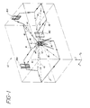
- Fig. 1 is an isometric view of the position sensing system of the present invention located at a point within a structured environment defined by four intersecting walls;
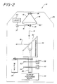
- Fig. 2 is a side view, with parts broken away, of a light transmitting and detecting means of the position sensing system of Fig. 1;
- Fig. 3 is an exploded partial top view of a rotating member illustrated in Fig. 2;
- Fig. 4 is a calibrating system which is used in conjunction with related software to calibrate the light transmitting and detecting means of Fig. 2 which includes the member of Fig. 3;
- Fig. 5 is a schematic block diagram of a hardware interface, controlled by software, which supports the position sensing system of the present invention, illustrating the interrelationship between the retroreflective elements shown in Fig. 1 and the light transmitting and detecting means shown in Fig. 2; and
- Figs. 6A and 6B illustrate a flow chart detailing the steps used in determining the Z-position of the point in space shown in Fig. 1.
- The three-dimensional position sensing system and method of the present invention is advantageously utilized in either a
structured environment 10, as shown in Fig. 1, or an external environment, to generate constantly updated information on the exact location of apoint 12. Typically, light transmitting and detecting means 14, best illustrated in Fig. 2, is positioned at thepoint 12 for transmitting a rotating beam oflight 16, which is emitted by a light source such aslaser 20 of Fig. 2, and reflected back to the light transmitting and detecting means 14 by a series of retroreflective elements 18. The position sensing system is also capable of determining the orientation of the light transmitting and detecting means 14 which is positioned at thepoint 12. The rotating beam oflight 16 should be of a size appropriate to create discernible START signals and END signals from each of the retroreflective elements 18, which preferably consist of distinctive retroreflective bar code elements in the form of a diagonal slant target from a top corner of the retroreflective element 18 to the opposing bottom corner in combination with a retroreflective bar code, as illustrated in Figs. 1 and 5. - The position sensing system has at least three stationary retroreflective elements 18, as typified by elements 18a, 18b, and 18c in Fig. 1. Preferably, the retroreflective elements 18a, 18b, and 18c are spaced apart from each other around the periphery of the frame of reference and stationed at known coordinates in the frame of
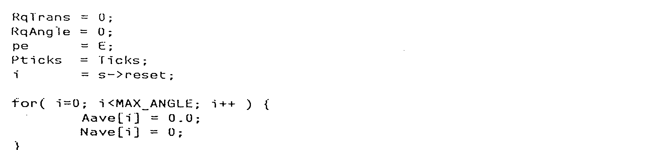
reference 10. In a preferred embodiment of the present invention, the retroreflective elements 18 are passive sensors, although active sensors may be used as well. With the passive sensor elements 18, the beam oflight 16 is reflected back to the light transmitting and detecting means 14. Thebeam 16 transmitted by the light transmitting and detecting means 14 has a varying zenith angle such that adynamic scan pattern 17 of thebeam 16 can scan theenvironment 10 at varying elevations to strike the retroreflective elements 18, regardless of the elevation of the elements 18. Azimuth and zenith means (not shown), responsive to the reflection of the beam oflight 16 from the retroreflective elements 18, continuously transmit angle signals, indicative of an azimuth and zenith angle at which the light transmitting and detecting means for receiving the beam of light is positioned with respect to each of the retroreflective elements 18, to acomputer 22 of Fig. 5. Thecomputer 22 includes a microprocessor, such as a Motorola 68030, having memory means for providing storage of software and data. A listing of exemplary software for performing the angle measurements in accordance with the present invention is as follows.


- Since the reflection from one passive element 18 looks the same as the reflection from each of the other passive elements 18, it cannot be determined from the reflection itself which element 18 is being illuminated. Therefore, according to one aspect of the present invention, any or all of the retroreflective elements 18a, 18b, and 18c can have a unique bar code in order to differentiate one element from the others. The moment of illumination of each retroreflective element 18 is registered extremely accurately since that moment is decisive for determining the angle within the angle of rotation of 360 degrees. By recognizing the retroreflective elements 18a, 18b, and 18c individually, it is possible to assign the proper coordinates to each element 18, which is necessary for the calculation of the position of the point and the determination of the orientation of the light transmitting and detecting
means 14 located at thepoint 12. Assigning a unique bar code to each element 18 distinguishes each of the elements 18a, 18b, and 18c from the others. Thecomputer 22 includes a microprocessor, such as a Motorola 68030, having memory means for providing storage of software and data. A listing of exemplary software for performing the bar code recognition of the present invention is as follows.

- Using the angle measurements and the recognized bar code patterns, the X-Y coordinates of the
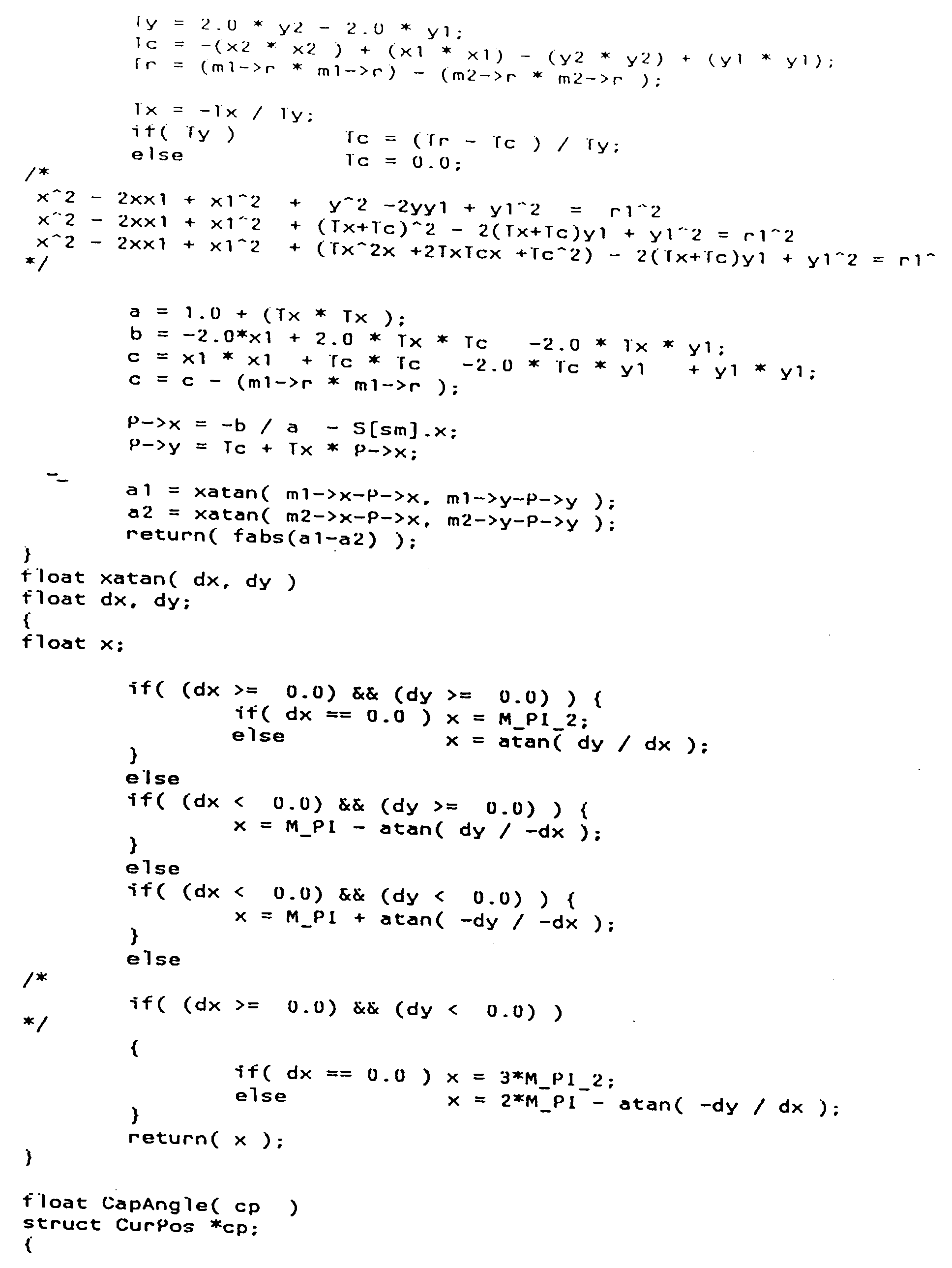
point 12 can be calculated by triangulation, and the Z coordinate is determined in accord with the flow chart of Figs. 6A and 6B. Thecomputer 22 includes a microprocessor, such as a Motorola 68030, having memory means for providing storage of software and data. A listing of exemplary software for performing the triangulation calculations of the present invention is as follows.


- Referring now to Fig. 2, a side view of a
housing 24 for the light transmitting and detectingmeans 14 is shown. The light transmitting and detectingmeans 14 includes anelectric motor 26 mounted to rotateshaft 28. Amember 30, such as a code wheel, and alight diverting mirror 32 are mounted on theshaft 28. A mirror positioning means 33 provides movement or positioning of themirror 32. The tilt of themirror 32 is known for a current position of themember 30 such that the vertical height of the retroreflective elements 18 are always known with respect to any horizontal point. - In the present invention, the
beam 16 has a variable zenith angle, which can be varied by changing the position of one ormore mirrors main mirror 32 can be tilted usingspring 39 which cooperates with the mirror positioning means 33. Alternatively,mirror 35 can be tilted in two dimensions in order to properly projectbeam 16 ontomirror 32. Yet another means for varying the zenith angle of thebeam 16 is to tiltmirror 37 independently or in conjunction withmirror 35.Mirror 37 is optional, however, as thelaser 20 may directbeam 16 straight atmirror 35. - An
index wheel 34 can also be included for providing a single reference pulse indicating each complete rotation of theshaft 28. A light source, such assolid state laser 20, directs the beam of light 16 onto the rotatingmirror 32 so that a plane of rotation is created. In a preferred embodiment of the invention, a generally horizontal plane of rotation is created. However, any plane of rotation, including vertical, can be created. In addition, thebeam 16 has a zenith angle which may be varied to produce a non-planar scan pattern. The retroreflective elements 18 are positioned in this plane or scan pattern. An advantage of the present invention is that a precisely horizontal or vertical plane or scan pattern is not essential for the three dimensional position calculation. As a result, the system may be used either by an operator as a handheld device as the operator moves about the environment of interest, or mounted on vehicles and other equipment as the equipment moves about a given area. - When the
rotating laser beam 16 strikes the retroreflective elements 18 during each revolution of theshaft 28, the beam oflight 16 is reflected back to the light transmitting and detectingmeans 14 and can be transformed into an analog signal by a suitable detector, such asphotodetector 36, and transmitted to a signal processing means 38 of Fig. 5, which outputs two digital signals. - Theoretically, the moment in time that a retroreflective element 18 has been illuminated with respect to the complete time of rotation is related to its angle, depending on which retroreflective element 18 is being illuminated by the
light beam 16, within a total angle of 360 degrees. However, this is only the case if the rotational speed of thebeam 16 is extremely constant. Typically, the rotational speed ofmotor shaft 28 which causes thebeam 16 to rotate is not perfectly constant and it is not possible to obtain a constant speed with the accuracy which is desired by the position sensing system of the present invention, especially in a mobile operation. Consequently, the position sensing system utilizes themotor 26 in conjunction with themember 30, supported by the dedicated hardware interface of Fig. 5 and controlled by software to achieve the desired accuracy. Thecomputer 22, having a microprocessor such as a Motorola 68030, contains software for a main routine which controls the hardware interface of the position sensing system, an exemplary listing of which is as follows.


- As shown in Fig. 3, the member or
code wheel 30 has a plurality of angularly positioned elements, preferably apertures 42, spaced around its periphery which divide a revolution of themember 30 into a plurality of generally equal partial revolutions. The size and spacing of these apertures are greatly exaggerated in the drawing for clarity of illustration. For example, thecode wheel 30 may divide a revolution into one thousand generally equal parts positioned approximately 0.36 degrees apart by spacing one thousand elements orapertures 42 around the periphery of themember 30. Although the distance between each adjacent pair ofapertures 42 theoretically represents a movement of 0.36 degrees, misalignment of themember 30, misalignment of the center of themember 30 through which theshaft 28 extends, and manufacturing tolerances, cause deviations in the spacing of theelements 42. However, since these deviations remain constant once the light transmitting and detectingmeans 14 is assembled, the actual angular spacing between eachelement 42 in themember 30 can be determined extremely precisely by a software calibration table. - Calibration of the code wheel or
member 30, preferably using software, improves accuracy by eliminating errors due to misalignments, deviations, and irregularities of the rotational speed of themotor 26. Any speed fluctuation of themotor 26 between twoapertures 42, particularly when there are one thousand such apertures spaced around the periphery of themember 30, will be negligible. Consequently, it is possible to interpolate between an adjacent pair of apertures, such as 42a and 42b in Fig. 3, to determine an exact angle between the pair of apertures 42a and 42b, according to the equation:
where42a is the measured angle of aperture 42a; 42b is the measured angle of aperture 42b; Tm is the time elapsed between passage of the previous aperture, here aperture 42a, and the moment M in time that the reflecting light strikes the sensor or
photodetector 36; and Tcw is the time it takes thecode wheel 30 to move between element 42a and element 42b. - One method of calibrating the code wheel or
member 30 is illustrated in Fig. 4 as acalibration system 44. To calibrate themember 30, the light transmitting and detectingmeans 14 containing thecode wheel 30, is placed on adevice 46 having an angularly positioned rotatingsurface 48, with themember 30 arbitrarily positioned. Thecomputer 22 of Fig. 5 controls astepper motor 50 associated with thesurface 48 and determines the number of steps between each pair ofadjacent elements 42 as themember 30 rotates. For instance, if one revolution of the member is defined as 360,000 steps, and themember 30 contains 1000 generally equally spacedelements 42, then each step would theoretically be expected to be equal to 0.001 degree, and eachelement 42 would be 0.36 degrees or 360 steps from eachadjacent element 42. However, in reality, there will be deviations in the spacing of theelements 42. Therefore, the actual spacing between each adjacent pair ofelements 42 is measured and can be stored in a calibration table, which table will remain accurate as long as the position sensing system of the present invention remains assembled. - Initially, in calibrating the
member 30, afirst element 42 receives a signal from a reference retroreflective element, and thisfirst element 42 becomes an index element for purposes of calibration of themember 30. Thecalibration system 44 determines when the index and followingelements 42 are in position to commence or end the counting of the steps betweenelements 42 by employing the interpolation equation from above. For theindex element 42, Tcw equals zero and Tm equals zero. As themember 30 rotates toward the nextadjacent element 42, Tm approaches zero and Tcw approaches 1. The moment in time when Tm is equal to zero and Tcw is equal to one, then theelement 42 is in position to end the counting of steps between the index element and the first adjacent element. This pattern continues until the number of steps and, thus, the distance in degrees between, each pair ofadjacent elements 42 has been determined. The calibratingsystem 44 is associated with thecomputer 22 which includes a microprocessor, such as a Motorola 68030, having a memory means for providing storage of software and data. A listing of exemplary software for performing the calibration of the light transmitting and detectingmeans 14 which includes themember 30 of the present invention is as follows.



- The position sensing system which combines the use of the
code wheel 30 and themotor 26 is supported by ahardware interface 52, illustrated in Fig. 5. An event occurs every time anaperture 42 on thecode wheel 30 passes, or a retroreflective element 18 commences or ends a reflection of the beam oflight 16. Due to the high precision time measurements required between each adjacent pair ofapertures 42, areference clock 54 is used in keeping a record of an event. If an event occurred during this time, it is stored in acircuit 56, such as a 32 bit first-in-first-out circuit. Thecircuit 56 records the movement of thecode wheel 30 at register 0. The actual element oraperture 42 which is currently passing is sensed at a member or code wheel pick upelement 58 and counted by amember rotation counter 60. Each time themember 30 has completed a full rotation, an index pick upelement 62 sends a signal to reset themember rotation counter 60. The member pick upelement 58 and the index pick upelement 62 comprise means for detecting movement of each of theelements 42 past a predetermined point as themember 30 rotates. In a preferred embodiment of the present invention, the pick upelements - The light transmitting and detecting
means 14 may include means for diverting and focusing the returning beam to thephotodetector 36. The rotatingmirror 32 diverts thelight beam 16 toward acollimating lens 40, whichlens 40 focuses thelight beam 16 toward thephotodetector 36. Signal processing means 38 detect when receivingoptics 64, consisting of collimatinglens 40 andphotodetector 36, is either commencing receipt of the reflection of thelight beam 16 or ending receipt of the reflection of thelight beam 16 from the retroreflective elements 18 to the light transmitting and detectingmeans 14 of Fig. 2. Signal processing means 38 can transform theanalog signal 41 fromphotodetector 36 into two digital signals which are received atregister 1 ofcircuit 56. The first digital signal represents a START signal which indicates if the reflection from retroreflective element 18 is commencing the reflection ofbeam 16 from the retroreflective elements 18 to the light transmitting and detectingmeans 14, and the second digital signal is an END signal which indicates if the reflection is ending.Register 2 receives signals for measuring the time elapsing between the passage of thelast aperture 42 and an event, which event may be the time Tm or the time Tcw shown in Fig. 3. Aclock pulse counter 66 is reset at a clock pulse forcounter 60 for eachaperture 42, which counter 66 counts the time elapsing between the passage of each pair ofadjacent elements 42. Information regarding the capacity of thecircuit 56 is stored inregister 3. - The
circuit 56 stores the information received and provides anoutput signal 68 to thecomputer 22 which includes a microprocessor having memory means. Thecomputer 22 is responsive to theoutput signal 68, to compute the coordinates of the position of thepoint 12 in the frame ofreference 10. When the light transmitting and detectingmeans 14 is positioned atpoint 12, thecomputer 22 also computes the orientation of the light transmitting and detectingmeans 14 within the frame ofreference 10. - Fig. 5 also illustrates the variable zenith angle of the beam which results from the tilt of any of the
mirrors beam 16 allows the position sensing system to scan anenvironment 10 and find all of the retroreflective elements 18 even when the elements 18 are not positioned at equal elevations. Referring back to Fig. 1, thedynamic scan pattern 17 can be tilted up or down as thebeam 16 approaches a retroreflective element 18 to permit thebeam 16 to strike the retroreflective element 18. - Referring now to Figs. 6A and 6B, a flow chart illustrating the steps for positioning or tilting a mirror and providing feedback regarding the Z position of the
point 12 of Fig. 1 is shown.Mirror 32 is used here by way of example and is not intended to be limiting, as any or all of themirrors beam 16. This information is then used for computing the X-Y-Z coordinates of thepoint 12. The flow chart is triggered in Fig. 6A by the main routine software atstep 70. Next, steps 72 and 74 require tilting themirror 32 of Fig. 2 to its upper limit and acquiring data relating to the position of themirror 32 as theshaft 28 rotates themirror 32 through one rotation. Atstep 76, the program determines which, if any, reflectors were found during the rotation of themirror 32 as themirror 32 was tilted to its upper limit. The exemplary software for performing angle measurements and bar code recognition may be applied to the program at this point. - Continuing with Fig. 6A,
decision block 78 determines whether the mirror has been tilted sufficiently to reach its lower limit of range. If not, themirror 32 is tilted slightly atblock 80. If themirror 32 has been tilted through its full range, the current X-Y position of thepoint 12 is computed atblock 82. The exemplary software for performing the triangulation calculations may be applied here before continuing to step 84 where the elevation of thebeam 16 striking the retroreflective elements 18 is calculated. The elevation can be determined using the known retroreflective element locations and the dark/light ratio reflection from the distinctive slant targets extending substantially diagonally from one top corner to the opposing bottom corner of the retroreflective elements 18 in combination with a retroreflective bar code. - The program continues to step 86 where an equation for the plane which intersects the
beam 16 is generated. Atstep 88, then, the program calculates the elevation of the plane at the current X-Y position computed atstep 82. Using the elevation of the plane at the current X-Y position and the known tilt angle of themirror 32 when thebeam 16 strikes the retroreflective elements 18, a Z position is calculated atstep 90. Then using the coordinates from previous rotations fromsteps step 92. - At
step 94, using the exemplary angle measurement software and bar code recognition software, the bar code and angle of the next retroreflective element to be struck by thebeam 16 are read.Decision block 96 of Fig. 6B then determines if a full rotation has occurred since the last position calculation. If not, the program returns to step 92. If so, the program continues todecision block 98 to determine if at least three retroreflective elements 18 were found. If so, the program returns to step 82. If not, the program continues to block 100 to calculate the probable new coordinates of thepoint 12 and establishes directions to the missing retroreflective elements 18, using coordinates of thepoint 12 from previous rotations. - Once the directions to the missing retroreflective elements 18 have been calculated, the program continues to step 102 where the
mirror 32 is tilted to scan slightly above the probable position of the missing retroreflective elements 18. Data is then acquired for one rotation of themirror 32 atstep 104, after which the program determines atstep 106 which, if any, of the missing retroreflective elements 18 were found. If the missing retroreflective elements 18 were found,decision block 108 directs the program to step 82. If the missing retroreflective elements 18 were not found, the program continues to decision block 110 to determine if themirror 32 was tilted to a position slightly below the missing retroreflective elements 18. If so, the program returns to step 72 and repeats. If not, the program continues to step 112 where themirror 32 is tilted slightly before returning to step 104 and again acquiring data for one rotation of the mirror. Using the steps detailed in the flow chart of Figs 6A and 6B, the movement and position of themirror 32 can be determined and applied to the X-Y-Z calculation of thepoint 12. - Having described the invention in detail and by way of reference to preferred embodiments thereof, it will be apparent that modifications and variations are possible without departing from the scope of the invention as defined in the appended claims.
Claims (14)
- A system for determining the position of a point (12) in three dimensional space, the system comprising:
at least three stationary retroreflective elements (18) spaced apart from each other and stationed at known coordinates, said retroreflective elements (18) capable of reflecting light back toward a light source (20);
light transmitting and detecting means (14), positionable at the point (12), for generating a rotating beam of light (16) to illuminate said stationary retroreflective elements (18) during rotation, and for detecting said beam of light (16) when it is reflected from said stationary retroreflective elements (18) and generating an output signal in response thereto; and
computer means (22) responsive to said output signal for computing from said known coordinates of said retroreflective elements (18) and from the angular orientation of said beam (16) when said beam (16) illuminates said retroreflective elements (18), the X-Y-Z coordinates of the position of the point (12) in space. - A system for determining the position of a point (12) as claimed in claim 1, characterized in that said computer means (22) are capable of determining an orientation of said light transmitting and detecting means (14) when said light transmitting and detecting means (14) are positioned at the point (12).
- A system for determining the position of a point (12) as claimed in claim 1 or 2, characterized in that said at least three stationary retroreflective elements (18) have a distinctive retroreflective slant target.
- A system for determining the position of a point (12) as claimed in claim 1 or 2, characterized in that said at least three retroreflective elements (18) have a distinctive combination of a retroreflective slant target extending substantially diagonally across each of said at lease three retroreflective elements (18) and a retroreflective bar code.
- A system for determining the position of a point (12) in three dimensional space, the system comprising:
at least three stationary retroreflective elements (18) spaced apart from each other and stationed at known coordinates, said retroreflective elements (18) capable of reflecting light back toward a light source (20);
light transmitting and detecting means (14), positionable at the point (12), for generating a rotating beam of light (16) to illuminate said stationary retroreflective elements (18) during rotation, and for detecting said beam of light (16) when it is reflected from said stationary retroreflective elements (18) and generating an output signal in response thereto, said light transmitting and detecting means (14) including
a member (30) rotating with said beam (16), said member (30) having a periphery and further having a plurality of angularly positioned elements (42) spaced around said periphery which divide a revolution of said member (30) into a plurality of generally equal partial revolutions, and
a means for detecting movement of each of said elements (42) past a predetermined point as said member (30) rotates; and
computer means (22), responsive to said output signal and said means for detecting movement of each of said elements (42) past a predetermined point, for computing the X-Y-Z coordinates of the position of the point (12) in space. - A system for determining the position of a point (12) as claimed in claim 5, characterized in that a calibrating system (44) is provided for calibrating said light transmitting and detecting means (14).
- A system for determining the position of a point (12) as claimed in claim 6, characterized in that said calibrating system (44) comprises a device having an angularly positioned surface for arbitrarily positioning said light transmitting and detecting means (14), wherein said light transmitting and detecting means (14) include said member (30) rotating with said beam (16); and means for measuring a distance between a first said angularly positioned element (42a) and an adjacent second said angularly positioned element (42b).
- A system for determining the position of a point (12) as claimed in claim 5, 6 or 7, characterized in that said plurality of angularly positioned elements (42) comprise a plurality of apertures.
- A system for determining the position of a point (12) as claimed in claim 5, 6 or 7, characterized in that said means for detecting movement of each of said elements (42) comprises a light source paired with a photodetector (36) element.
- A system for determining the position of a point (12) in space, the system comprising:
at least three stationary retroreflective elements (18) spaced apart from each other and stationed at known coordinates, said retroreflective elements (18) capable of reflecting light back toward a light source (20);
light transmitting and detecting means (14) positionable at the point for generating a rotating beam of light (16) to illuminate said stationary retroreflective elements (18) during rotation and for receiving said beam of light (16) reflected from said stationary retroreflective elements (18) when said beam (16) illuminates said retroreflective elements (18), said light transmitting and detecting means (14) including
an optical member (30) rotating with said beam (16), said member (30) having a periphery and further having a plurality of apertures (42) located at said periphery which divide a revolution of said member (30) into a plurality of generally equal partial revolutions,
a means for registering a time differential between each adjacent pair of said plurality of apertures (42) as said member (30) rotates,
a means for registering a tilt position of one or more reflecting mirrors positioned at said light transmitting and detecting means (14), and
a means for calculating a zenith angle of said beam based on said mirror position (32); and
computer means (22), responsive to said output signal and said means for detecting movement of each of said elements (18) past a predetermined point, for computing the coordinates of the position of the point (12) in space and for computing an orientation for said light transmitting and detecting means (14) when said light transmitting and detecting (14) means are positioned at said point (12). - A method for determining the position of a point (12) in three dimensional space, the method comprising the steps of:
locating at least three stationary retroreflective elements (18) spaced apart from each other and stationed at known coordinates, said retroreflective elements (18) capable of reflecting light back toward a light source (20);
transmitting a rotating beam of light (16) to illuminate said stationary retroreflective elements (18) during rotation;
measuring an angular position of said retroreflective elements (18) with respect to a known reference;
tracking scan behavior;
using said scan behavior to calculate angular measurements; and
determining the three dimensional position of the point (12) dimensional based on said angular measurements and said coordinates of said retroreflective elements (18). - A method for determining the position of a point (12) as claimed in claim 11, characterized in that said step of tracking scan behavior further includes the steps of mounting a member (30) on a rotating shaft, said member (30) having a periphery and further having a plurality of apertures (42) located at said periphery which divide a revolution of said member (30) into a plurality of generally equal partial revolutions; and registering a time differential between each adjacent pair of said plurality of apertures (42) as said member (30) rotates
- A method for determining the position of a point (12) as claimed in claim 11 or 12, characterized in that said step of determining the position of the point (12) further includes the step of determining an orientation for said rotating beam of light (16) when said rotating beam of light (16) is positioned at the point (12).
- A method for determining the position of a point (12) as claimed in claim 11, 12 or 13, further including the step of interpolating between corresponding angle measurements of an adjacent pair of said plurality of apertures (42) to determine exact angles between each said pair of apertures (42).
Applications Claiming Priority (2)
| Application Number | Priority Date | Filing Date | Title |
|---|---|---|---|
| US55428790A | 1990-07-18 | 1990-07-18 | |
| US554287 | 1990-07-18 |
Publications (3)
| Publication Number | Publication Date |
|---|---|
| EP0468677A2 true EP0468677A2 (en) | 1992-01-29 |
| EP0468677A3 EP0468677A3 (en) | 1992-11-25 |
| EP0468677B1 EP0468677B1 (en) | 1996-05-15 |
Family
ID=24212786
Family Applications (1)
| Application Number | Title | Priority Date | Filing Date |
|---|---|---|---|
| EP91306376A Expired - Lifetime EP0468677B1 (en) | 1990-07-18 | 1991-07-15 | Three dimensional position sensing system and method |
Country Status (3)
| Country | Link |
|---|---|
| US (1) | US5137354A (en) |
| EP (1) | EP0468677B1 (en) |
| DE (1) | DE69119500T2 (en) |
Cited By (11)
| Publication number | Priority date | Publication date | Assignee | Title |
|---|---|---|---|---|
| WO1995004944A1 (en) * | 1993-08-10 | 1995-02-16 | Fmc Corporation | Apparatus and method for identifying scanned reflective anonymous targets |
| EP0643283A1 (en) * | 1993-09-09 | 1995-03-15 | Kabushiki Kaisha Topcon | Object reflector detection system |
| FR2721395A1 (en) * | 1994-06-17 | 1995-12-22 | Homer Eaton | Method for locating a trihedron in space and device for implementing this method. |
| EP0742446A1 (en) * | 1995-05-09 | 1996-11-13 | FINMECCANICA S.p.A. AZIENDA ANSALDO | A method and apparatus for determining the relative positioning of bodies |
| GB2301185A (en) * | 1995-05-09 | 1996-11-27 | Cementation Piling & Found | Positioning system |
| US6108076A (en) * | 1998-12-21 | 2000-08-22 | Trimble Navigation Limited | Method and apparatus for accurately positioning a tool on a mobile machine using on-board laser and positioning system |
| US6253160B1 (en) | 1999-01-15 | 2001-06-26 | Trimble Navigation Ltd. | Method and apparatus for calibrating a tool positioning mechanism on a mobile machine |
| GB2399965A (en) * | 2003-03-24 | 2004-09-29 | Morgan Crucible Co | System for determining the three dimensional position of an article |
| EP1517117A1 (en) * | 2003-09-22 | 2005-03-23 | Leica Geosystems AG | Method and system for the determination of the actual position of a positioning apparatus |
| EP0806630B1 (en) * | 1995-10-30 | 2005-05-25 | Kabushiki Kaisha Topcon | Rotary laser system |
| EP1580527A3 (en) * | 2004-03-23 | 2008-04-23 | Kabushiki Kaisha Topcon | Laser measuring method and laser measuring system |
Families Citing this family (65)
| Publication number | Priority date | Publication date | Assignee | Title |
|---|---|---|---|---|
| JPH0833767B2 (en) * | 1990-04-20 | 1996-03-29 | 本田技研工業株式会社 | Steering control device for self-propelled vehicle |
| AU641315B2 (en) * | 1991-04-11 | 1993-09-16 | Honda Giken Kogyo Kabushiki Kaisha | System for detecting the position of moving body |
| US5301005A (en) * | 1993-02-10 | 1994-04-05 | Spectra-Physics Laserplane, Inc. | Method and apparatus for determining the position of a retroreflective element |
| US5583323A (en) * | 1993-11-05 | 1996-12-10 | Microfield Graphics, Inc. | Calibration of graphic data-acquisition tracking system |
| US5585605A (en) * | 1993-11-05 | 1996-12-17 | Microfield Graphics, Inc. | Optical-scanning system employing laser and laser safety control |
| US5546217A (en) * | 1993-11-05 | 1996-08-13 | Decagon Devices, Inc. | Laser scanning apparatus |
| US5434370A (en) * | 1993-11-05 | 1995-07-18 | Microfield Graphics, Inc. | Marking system with pen-up/pen-down tracking |
| US9310167B1 (en) | 1995-11-28 | 2016-04-12 | Bae Systems Information And Electronic Systems Integration Inc. | Compact infrared countermeasure emitter |
| US5742384A (en) * | 1996-05-02 | 1998-04-21 | Lockheed Martin Corporation | Compact scanning infrared countermeasure emitter |
| US5844222A (en) * | 1996-07-02 | 1998-12-01 | Intermec Corporation | Rastering laser scanner with beam location feedback |
| US6082186A (en) * | 1997-04-23 | 2000-07-04 | Ncr Corporation | Adjustable balance weight |
| US6043874A (en) * | 1998-04-10 | 2000-03-28 | Spectra Precision, Inc. | System and method for calibrating a laser transmitter |
| US6198528B1 (en) * | 1998-05-22 | 2001-03-06 | Trimble Navigation Ltd | Laser-based three dimensional tracking system |
| JP4180718B2 (en) * | 1999-01-29 | 2008-11-12 | 株式会社トプコン | Rotating laser device |
| US6480271B1 (en) * | 2001-01-08 | 2002-11-12 | The Boeing Company | Traversing laser locating system |
| US6598692B2 (en) | 2001-10-16 | 2003-07-29 | Self-Guided Systems, L.L.C. | Vehicle guidance-maintaining horizontal laser |
| US6853445B2 (en) * | 2002-01-07 | 2005-02-08 | Motorola, Inc. | Two-dimensional angle of arrival detection device |
| JP3995041B2 (en) * | 2002-07-10 | 2007-10-24 | 株式会社トプコン | Laser irradiation device |
| US6922252B2 (en) * | 2002-09-19 | 2005-07-26 | Process Matrix, Llc | Automated positioning method for contouring measurements using a mobile range measurement system |
| US7230724B2 (en) * | 2005-04-15 | 2007-06-12 | Specialty Minerals (Michigan) Inc. | Three-dimensional measuring apparatus for scanning an object and a measurement head of a three-dimensional measuring apparatus and method of using the same |
| US20060232762A1 (en) * | 2005-04-15 | 2006-10-19 | Specialty Minerals (Michigan) Inc. | Optical element, measuring apparatus and measuring method |
| US20060232763A1 (en) * | 2005-04-15 | 2006-10-19 | Specialty Minerals (Michigan) Inc. | Optical element, measuring apparatus and measuring method |
| US7259838B2 (en) * | 2005-06-17 | 2007-08-21 | Specialty Minerals (Michigan) Inc. | Optical beam separation element, measuring apparatus and method of measuring |
| DE102006013185A1 (en) * | 2006-03-22 | 2007-09-27 | Refractory Intellectual Property Gmbh & Co. Kg | Method for determining the position and orientation of a measuring or repair device and a device operating according to the method |
| US7806585B2 (en) * | 2007-06-22 | 2010-10-05 | Decagon Devices, Inc. | Apparatus, method, and system for measuring water activity and weight |
| JP5202097B2 (en) * | 2008-05-14 | 2013-06-05 | 株式会社キーエンス | Optical scanning photoelectric switch |
| JP5156475B2 (en) * | 2008-05-14 | 2013-03-06 | 株式会社キーエンス | Optical scanning photoelectric switch |
| JP5036624B2 (en) * | 2008-05-20 | 2012-09-26 | 株式会社キーエンス | Monitoring area setting device |
| JP5096235B2 (en) * | 2008-06-03 | 2012-12-12 | 株式会社キーエンス | Area monitoring sensor |
| JP5086899B2 (en) * | 2008-06-03 | 2012-11-28 | 株式会社キーエンス | Area monitoring sensor |
| US9482755B2 (en) | 2008-11-17 | 2016-11-01 | Faro Technologies, Inc. | Measurement system having air temperature compensation between a target and a laser tracker |
| WO2012141810A1 (en) | 2011-03-03 | 2012-10-18 | Faro Technologies, Inc. | Target apparatus and method |
| JP5473044B2 (en) * | 2009-01-31 | 2014-04-16 | 株式会社キーエンス | Safety photoelectric switch |
| JP2010175488A (en) * | 2009-01-31 | 2010-08-12 | Keyence Corp | Optical scan type photoelectric switch |
| US8415609B2 (en) | 2009-01-31 | 2013-04-09 | Keyence Corporation | Safety photoelectric switch |
| US8537371B2 (en) | 2010-04-21 | 2013-09-17 | Faro Technologies, Inc. | Method and apparatus for using gestures to control a laser tracker |
| US8619265B2 (en) | 2011-03-14 | 2013-12-31 | Faro Technologies, Inc. | Automatic measurement of dimensional data with a laser tracker |
| US9772394B2 (en) | 2010-04-21 | 2017-09-26 | Faro Technologies, Inc. | Method and apparatus for following an operator and locking onto a retroreflector with a laser tracker |
| US9400170B2 (en) | 2010-04-21 | 2016-07-26 | Faro Technologies, Inc. | Automatic measurement of dimensional data within an acceptance region by a laser tracker |
| US9377885B2 (en) | 2010-04-21 | 2016-06-28 | Faro Technologies, Inc. | Method and apparatus for locking onto a retroreflector with a laser tracker |
| US8422034B2 (en) * | 2010-04-21 | 2013-04-16 | Faro Technologies, Inc. | Method and apparatus for using gestures to control a laser tracker |
| US8724119B2 (en) | 2010-04-21 | 2014-05-13 | Faro Technologies, Inc. | Method for using a handheld appliance to select, lock onto, and track a retroreflector with a laser tracker |
| US8943701B2 (en) * | 2010-06-28 | 2015-02-03 | Trimble Navigation Limited | Automated layout and point transfer system |
| US8087176B1 (en) | 2010-06-28 | 2012-01-03 | Trimble Navigation Ltd | Two dimension layout and point transfer system |
| EP2453204A1 (en) * | 2010-11-10 | 2012-05-16 | Leica Geosystems AG | Construction laser system and method |
| US9686532B2 (en) | 2011-04-15 | 2017-06-20 | Faro Technologies, Inc. | System and method of acquiring three-dimensional coordinates using multiple coordinate measurement devices |
| US9482529B2 (en) | 2011-04-15 | 2016-11-01 | Faro Technologies, Inc. | Three-dimensional coordinate scanner and method of operation |
| US9164173B2 (en) | 2011-04-15 | 2015-10-20 | Faro Technologies, Inc. | Laser tracker that uses a fiber-optic coupler and an achromatic launch to align and collimate two wavelengths of light |
| GB2504890A (en) | 2011-04-15 | 2014-02-12 | Faro Tech Inc | Enhanced position detector in laser tracker |
| US8817239B2 (en) * | 2011-07-01 | 2014-08-26 | Trimble Navigation Limited | Distance based position sensing |
| JP6099675B2 (en) | 2012-01-27 | 2017-03-22 | ファロ テクノロジーズ インコーポレーテッド | Inspection method by barcode identification |
| US9041914B2 (en) | 2013-03-15 | 2015-05-26 | Faro Technologies, Inc. | Three-dimensional coordinate scanner and method of operation |
| US10165255B2 (en) | 2013-03-20 | 2018-12-25 | Trimble Inc. | Indoor navigation via multi-beam laser projection |
| US10643351B2 (en) | 2013-03-20 | 2020-05-05 | Trimble Inc. | Indoor navigation via multi beam laser projection |
| KR101883121B1 (en) * | 2014-06-13 | 2018-07-27 | 미쓰비시덴키 가부시키가이샤 | Device for measuring elevator hoistway dimensions, and method for measuring same |
| US9395174B2 (en) | 2014-06-27 | 2016-07-19 | Faro Technologies, Inc. | Determining retroreflector orientation by optimizing spatial fit |
| CN105629200B (en) * | 2016-03-16 | 2018-05-15 | 北京国承万通信息科技有限公司 | Positioning beam emission system, method and indoor positioning system |
| US9880022B1 (en) | 2016-11-14 | 2018-01-30 | Trimble Navigation Limited | Point layout system with third transmitter |
| US11226199B2 (en) | 2017-01-17 | 2022-01-18 | Trimble Navigation Limited | Point layout system using single laser transmitter |
| US10690498B2 (en) | 2017-05-10 | 2020-06-23 | Trimble, Inc. | Automatic point layout and staking system |
| US11435182B2 (en) | 2019-12-20 | 2022-09-06 | Trimble, Inc. | Laser receiver and target with lighted indicators |
| US11435445B2 (en) | 2019-12-20 | 2022-09-06 | Trimble, Inc. | Laser receiver and target with lighted indicators |
| FR3108430B1 (en) * | 2020-03-18 | 2022-04-15 | Marc Lecomte | Alarm and monitoring system |
| JP7497553B2 (en) * | 2020-09-29 | 2024-06-11 | 株式会社トプコン | Marking system, marking method |
| US12152879B1 (en) * | 2024-07-30 | 2024-11-26 | Rigoberto Renteria | Layout marking system for tracing reference regions in a construction layout and a method thereof |
Family Cites Families (17)
| Publication number | Priority date | Publication date | Assignee | Title |
|---|---|---|---|---|
| US3458709A (en) * | 1964-06-24 | 1969-07-29 | North American Rockwell | Time reference angle encoder using radiation sensitive means |
| US3588249A (en) * | 1968-06-17 | 1971-06-28 | Robert H Studebaker | Laser beam survey apparatus |
| US3813171A (en) * | 1973-01-11 | 1974-05-28 | Laserplane Corp | Laser beam survey method and apparatus |
| US3873226A (en) * | 1973-07-11 | 1975-03-25 | Laserplane Corp | Laser beam control system for road paving machines |
| US4030832A (en) * | 1975-02-10 | 1977-06-21 | Spectra-Physics, Inc. | Automatic grade rod and method of operation |
| US3997071A (en) * | 1975-08-14 | 1976-12-14 | Laserplane Corporation | Method and apparatus for indicating effective digging depth of a backhoe |
| US4034490A (en) * | 1975-11-03 | 1977-07-12 | Laserplane Corporation | Automatic depth control for endless chain type trencher |
| US4035084A (en) * | 1976-02-19 | 1977-07-12 | Ramsay James D | Automatic levelling method and apparatus for rotating laser beam transmitter |
| US4113381A (en) * | 1976-11-18 | 1978-09-12 | Hewlett-Packard Company | Surveying instrument and method |
| US4355895A (en) * | 1979-07-26 | 1982-10-26 | Coal Industry (Patents) Limited | Survey systems |
| DE3321990C2 (en) * | 1983-06-18 | 1986-12-18 | Nestle & Fischer, 7295 Dornstetten | Measuring stick for a laser-optical leveling system |
| CH676043A5 (en) * | 1983-12-30 | 1990-11-30 | Wild Leitz Ag | |
| SE451770B (en) * | 1985-09-17 | 1987-10-26 | Hyypae Ilkka Kalevi | KIT FOR NAVIGATION OF A LARGE VESSEL IN ONE PLAN, EXTRA A TRUCK, AND TRUCK FOR EXTENDING THE KIT |
| US4830489A (en) * | 1986-08-20 | 1989-05-16 | Spectra-Physics, Inc. | Three dimensional laser beam survey system |
| US4796198A (en) * | 1986-10-17 | 1989-01-03 | The United States Of America As Represented By The United States Department Of Energy | Method for laser-based two-dimensional navigation system in a structured environment |
| US4918607A (en) * | 1988-09-09 | 1990-04-17 | Caterpillar Industrial Inc. | Vehicle guidance system |
| US5076690A (en) * | 1990-05-14 | 1991-12-31 | Spectra-Physics Laserplane, Inc. | Computer aided positioning system and method |
-
1991
- 1991-07-15 DE DE69119500T patent/DE69119500T2/en not_active Expired - Fee Related
- 1991-07-15 EP EP91306376A patent/EP0468677B1/en not_active Expired - Lifetime
- 1991-08-01 US US07/740,649 patent/US5137354A/en not_active Expired - Fee Related
Cited By (17)
| Publication number | Priority date | Publication date | Assignee | Title |
|---|---|---|---|---|
| WO1995004944A1 (en) * | 1993-08-10 | 1995-02-16 | Fmc Corporation | Apparatus and method for identifying scanned reflective anonymous targets |
| EP0643283A1 (en) * | 1993-09-09 | 1995-03-15 | Kabushiki Kaisha Topcon | Object reflector detection system |
| FR2721395A1 (en) * | 1994-06-17 | 1995-12-22 | Homer Eaton | Method for locating a trihedron in space and device for implementing this method. |
| WO1995035479A1 (en) * | 1994-06-17 | 1995-12-28 | Homer Eaton | Method and device for spatially locating a trihedron |
| US5757499A (en) * | 1994-06-17 | 1998-05-26 | Eaton; Homer | Method of locating the spatial position of a frame of reference and apparatus for implementing the method |
| EP0742446A1 (en) * | 1995-05-09 | 1996-11-13 | FINMECCANICA S.p.A. AZIENDA ANSALDO | A method and apparatus for determining the relative positioning of bodies |
| GB2301185A (en) * | 1995-05-09 | 1996-11-27 | Cementation Piling & Found | Positioning system |
| GB2301185B (en) * | 1995-05-09 | 1998-05-20 | Cementation Piling & Found | Improved positioning system |
| EP0806630B1 (en) * | 1995-10-30 | 2005-05-25 | Kabushiki Kaisha Topcon | Rotary laser system |
| US6108076A (en) * | 1998-12-21 | 2000-08-22 | Trimble Navigation Limited | Method and apparatus for accurately positioning a tool on a mobile machine using on-board laser and positioning system |
| US6253160B1 (en) | 1999-01-15 | 2001-06-26 | Trimble Navigation Ltd. | Method and apparatus for calibrating a tool positioning mechanism on a mobile machine |
| GB2399965A (en) * | 2003-03-24 | 2004-09-29 | Morgan Crucible Co | System for determining the three dimensional position of an article |
| EP1517117A1 (en) * | 2003-09-22 | 2005-03-23 | Leica Geosystems AG | Method and system for the determination of the actual position of a positioning apparatus |
| WO2005031259A1 (en) * | 2003-09-22 | 2005-04-07 | Leica Geosystems Ag | Method and system for determining the spatial position of a hand-held measuring appliance |
| CN100580373C (en) * | 2003-09-22 | 2010-01-13 | 莱卡地球系统公开股份有限公司 | Method and system for determining the spatial location of a hand-held measuring instrument |
| US7742176B2 (en) | 2003-09-22 | 2010-06-22 | Leica Geosystems Ag | Method and system for determining the spatial position of a hand-held measuring appliance |
| EP1580527A3 (en) * | 2004-03-23 | 2008-04-23 | Kabushiki Kaisha Topcon | Laser measuring method and laser measuring system |
Also Published As
| Publication number | Publication date |
|---|---|
| US5137354A (en) | 1992-08-11 |
| DE69119500T2 (en) | 1996-11-14 |
| EP0468677B1 (en) | 1996-05-15 |
| DE69119500D1 (en) | 1996-06-20 |
| EP0468677A3 (en) | 1992-11-25 |
Similar Documents
| Publication | Publication Date | Title |
|---|---|---|
| US5137354A (en) | Computer aided three dimensional positioning sensing system and method | |
| US5076690A (en) | Computer aided positioning system and method | |
| JP7163085B2 (en) | Surveying method, surveying device and program | |
| US5301005A (en) | Method and apparatus for determining the position of a retroreflective element | |
| US6545751B2 (en) | Low cost 2D position measurement system and method | |
| US6501543B2 (en) | Apparatus and method for determining position | |
| US7876457B2 (en) | Laser metrology system and method | |
| US8896848B2 (en) | Method and apparatus for using gestures to control a laser tracker | |
| EP3514489B1 (en) | Surveying device and surveying method | |
| EP0532125B1 (en) | A measuring apparatus for determining the position of a movable element with respect to a reference | |
| US20030174305A1 (en) | Measuring device and measuring method for determining distance and/or position | |
| US20030043362A1 (en) | Six dimensional laser tracking system and method | |
| US20020154294A1 (en) | Position measurement system and method using cone math calibration | |
| EP3401639A1 (en) | Surveying system | |
| EP1983299B1 (en) | Apparatus and method for determining an elevation of working tools based on a laser system | |
| KR20040002162A (en) | Apparatus and method of localization using laser | |
| CN110850430B (en) | Laser scanning system | |
| US20070201040A1 (en) | Laser-based position measuring device | |
| US10267659B2 (en) | Angle detecting device and surveying instrument | |
| EP3696499B1 (en) | Surveying system having a rotating mirror | |
| KR100192851B1 (en) | Position attitude measuring method and device of tunnel excavator | |
| JPH02122307A (en) | Dynamic control/guide system | |
| JP2945467B2 (en) | Machine height measuring device | |
| JP2694647B2 (en) | Distance measuring theodolite | |
| US10684124B1 (en) | Scanning and measurement system for repair of structures |
Legal Events
| Date | Code | Title | Description |
|---|---|---|---|
| PUAI | Public reference made under article 153(3) epc to a published international application that has entered the european phase |
Free format text: ORIGINAL CODE: 0009012 |
|
| AK | Designated contracting states |
Kind code of ref document: A2 Designated state(s): CH DE FR GB LI NL |
|
| RIN1 | Information on inventor provided before grant (corrected) |
Inventor name: SCHOUTEN, JOHANNES N.TH. Inventor name: DEVOS, LEON B.C. |
|
| PUAL | Search report despatched |
Free format text: ORIGINAL CODE: 0009013 |
|
| AK | Designated contracting states |
Kind code of ref document: A3 Designated state(s): CH DE FR GB LI NL |
|
| 17P | Request for examination filed |
Effective date: 19930128 |
|
| 17Q | First examination report despatched |
Effective date: 19940517 |
|
| GRAH | Despatch of communication of intention to grant a patent |
Free format text: ORIGINAL CODE: EPIDOS IGRA |
|
| GRAA | (expected) grant |
Free format text: ORIGINAL CODE: 0009210 |
|
| AK | Designated contracting states |
Kind code of ref document: B1 Designated state(s): CH DE FR GB LI NL |
|
| REF | Corresponds to: |
Ref document number: 69119500 Country of ref document: DE Date of ref document: 19960620 |
|
| ET | Fr: translation filed | ||
| REG | Reference to a national code |
Ref country code: CH Ref legal event code: NV Representative=s name: PATENTANWAELTE SCHAAD, BALASS, MENZL & PARTNER AG |
|
| PLBE | No opposition filed within time limit |
Free format text: ORIGINAL CODE: 0009261 |
|
| STAA | Information on the status of an ep patent application or granted ep patent |
Free format text: STATUS: NO OPPOSITION FILED WITHIN TIME LIMIT |
|
| 26N | No opposition filed | ||
| PGFP | Annual fee paid to national office [announced via postgrant information from national office to epo] |
Ref country code: FR Payment date: 19970721 Year of fee payment: 7 |
|
| PGFP | Annual fee paid to national office [announced via postgrant information from national office to epo] |
Ref country code: GB Payment date: 19970728 Year of fee payment: 7 |
|
| PGFP | Annual fee paid to national office [announced via postgrant information from national office to epo] |
Ref country code: CH Payment date: 19970805 Year of fee payment: 7 |
|
| REG | Reference to a national code |
Ref country code: CH Ref legal event code: PFA Free format text: SPECTRA-PHYSICS LASERPLANE, INC. TRANSFER- SPECTRA PRECISION, INC.. |
|
| REG | Reference to a national code |
Ref country code: FR Ref legal event code: CD |
|
| NLT1 | Nl: modifications of names registered in virtue of documents presented to the patent office pursuant to art. 16 a, paragraph 1 |
Owner name: SPECTRA PRECISION, INC. |
|
| PG25 | Lapsed in a contracting state [announced via postgrant information from national office to epo] |
Ref country code: GB Free format text: LAPSE BECAUSE OF NON-PAYMENT OF DUE FEES Effective date: 19980715 |
|
| PG25 | Lapsed in a contracting state [announced via postgrant information from national office to epo] |
Ref country code: LI Free format text: LAPSE BECAUSE OF NON-PAYMENT OF DUE FEES Effective date: 19980731 Ref country code: CH Free format text: LAPSE BECAUSE OF NON-PAYMENT OF DUE FEES Effective date: 19980731 |
|
| GBPC | Gb: european patent ceased through non-payment of renewal fee |
Effective date: 19980715 |
|
| REG | Reference to a national code |
Ref country code: CH Ref legal event code: PL |
|
| PG25 | Lapsed in a contracting state [announced via postgrant information from national office to epo] |
Ref country code: FR Free format text: LAPSE BECAUSE OF NON-PAYMENT OF DUE FEES Effective date: 19990331 |
|
| REG | Reference to a national code |
Ref country code: FR Ref legal event code: ST |
|
| PGFP | Annual fee paid to national office [announced via postgrant information from national office to epo] |
Ref country code: NL Payment date: 20030703 Year of fee payment: 13 |
|
| PGFP | Annual fee paid to national office [announced via postgrant information from national office to epo] |
Ref country code: DE Payment date: 20030731 Year of fee payment: 13 |
|
| NLS | Nl: assignments of ep-patents |
Owner name: TRIMBLE NAVIGATION LIMITED |
|
| PG25 | Lapsed in a contracting state [announced via postgrant information from national office to epo] |
Ref country code: NL Free format text: LAPSE BECAUSE OF NON-PAYMENT OF DUE FEES Effective date: 20050201 Ref country code: DE Free format text: LAPSE BECAUSE OF NON-PAYMENT OF DUE FEES Effective date: 20050201 |
|
| NLV4 | Nl: lapsed or anulled due to non-payment of the annual fee |
Effective date: 20050201 |