EP0468679B1 - Elément de fixation auto-forant avec un garrot - Google Patents
Elément de fixation auto-forant avec un garrot Download PDFInfo
- Publication number
- EP0468679B1 EP0468679B1 EP91306412A EP91306412A EP0468679B1 EP 0468679 B1 EP0468679 B1 EP 0468679B1 EP 91306412 A EP91306412 A EP 91306412A EP 91306412 A EP91306412 A EP 91306412A EP 0468679 B1 EP0468679 B1 EP 0468679B1
- Authority
- EP
- European Patent Office
- Prior art keywords
- toggle clamp
- fastener
- toggle
- screw
- fastener body
- Prior art date
- Legal status (The legal status is an assumption and is not a legal conclusion. Google has not performed a legal analysis and makes no representation as to the accuracy of the status listed.)
- Expired - Lifetime
Links
- 238000005553 drilling Methods 0.000 title claims description 33
- 230000037431 insertion Effects 0.000 claims description 48
- 238000003780 insertion Methods 0.000 claims description 48
- 230000000694 effects Effects 0.000 claims description 2
- 239000000463 material Substances 0.000 description 11
- 239000011507 gypsum plaster Substances 0.000 description 4
- HCHKCACWOHOZIP-UHFFFAOYSA-N Zinc Chemical compound [Zn] HCHKCACWOHOZIP-UHFFFAOYSA-N 0.000 description 3
- 239000002184 metal Substances 0.000 description 3
- 229910052751 metal Inorganic materials 0.000 description 3
- 229910052725 zinc Inorganic materials 0.000 description 3
- 239000011701 zinc Substances 0.000 description 3
- 229920000098 polyolefin Polymers 0.000 description 2
- 238000004512 die casting Methods 0.000 description 1
- 238000010137 moulding (plastic) Methods 0.000 description 1
- 239000011505 plaster Substances 0.000 description 1
- 239000004575 stone Substances 0.000 description 1
- 239000002023 wood Substances 0.000 description 1
Images


Classifications
-
- F—MECHANICAL ENGINEERING; LIGHTING; HEATING; WEAPONS; BLASTING
- F16—ENGINEERING ELEMENTS AND UNITS; GENERAL MEASURES FOR PRODUCING AND MAINTAINING EFFECTIVE FUNCTIONING OF MACHINES OR INSTALLATIONS; THERMAL INSULATION IN GENERAL
- F16B—DEVICES FOR FASTENING OR SECURING CONSTRUCTIONAL ELEMENTS OR MACHINE PARTS TOGETHER, e.g. NAILS, BOLTS, CIRCLIPS, CLAMPS, CLIPS OR WEDGES; JOINTS OR JOINTING
- F16B13/00—Dowels or other devices fastened in walls or the like by inserting them in holes made therein for that purpose
- F16B13/04—Dowels or other devices fastened in walls or the like by inserting them in holes made therein for that purpose with parts gripping in the hole or behind the reverse side of the wall after inserting from the front
- F16B13/08—Dowels or other devices fastened in walls or the like by inserting them in holes made therein for that purpose with parts gripping in the hole or behind the reverse side of the wall after inserting from the front with separate or non-separate gripping parts moved into their final position in relation to the body of the device without further manual operation
- F16B13/0808—Dowels or other devices fastened in walls or the like by inserting them in holes made therein for that purpose with parts gripping in the hole or behind the reverse side of the wall after inserting from the front with separate or non-separate gripping parts moved into their final position in relation to the body of the device without further manual operation by a toggle-mechanism
-
- F—MECHANICAL ENGINEERING; LIGHTING; HEATING; WEAPONS; BLASTING
- F16—ENGINEERING ELEMENTS AND UNITS; GENERAL MEASURES FOR PRODUCING AND MAINTAINING EFFECTIVE FUNCTIONING OF MACHINES OR INSTALLATIONS; THERMAL INSULATION IN GENERAL
- F16B—DEVICES FOR FASTENING OR SECURING CONSTRUCTIONAL ELEMENTS OR MACHINE PARTS TOGETHER, e.g. NAILS, BOLTS, CIRCLIPS, CLAMPS, CLIPS OR WEDGES; JOINTS OR JOINTING
- F16B13/00—Dowels or other devices fastened in walls or the like by inserting them in holes made therein for that purpose
- F16B13/002—Dowels or other devices fastened in walls or the like by inserting them in holes made therein for that purpose self-cutting
Definitions
- This invention relates to an improved fastener including a toggle clamp and being capable of being mounted in a plasterboard or similar wall from one side only of the wall (US-A-4 047 462).
- a plasterboard wall comprises a core of friable material, such as gypsum plaster, between two paper layers. It is difficult to mount a heavy object to such a wall. The core easily crumbles and the paper layers are easily torn.
- a blind fastener of a type including a toggle clamp is used to mount an object to a plasterboard or similar wall.
- a blind fastener is a fastener capable of being mounted to a wall from one side of the wall.
- Self-drilling fasteners are well known for insertion into harder, less friable materials such as concrete and stone.
- a fastener is shown in DE-A-2,945,663 which discloses a self-drilling anchor which forms a hole in a hard material, and is then expanded to grip the sides of the hole.
- Such a fastener is totally unsuitable for friable material such as plasterboard, firstly the plasterboard will be destroyed by the insertion of fastener, and secondly a secure fixing in plasterboard cannot be achieved by expanding the fastener radially to contact the inside walls of a hole.
- a fastener capable of being drilled into a friable wall such as plasterboard, and of being used with a screw having a head and an elongate shank with a threaded portion, the fastener comprising:
- the toggle clamp has a ramp.
- the ramp is arranged to be axially engaged by the screw, as the shank of the screw is driven into the bore, to pivot the toggle clamp from the insertion position into the toggle position.
- the body includes a pair of arms and each of the arms has an axially extending slot and the toggle clamp has a pair of oppositely extending pintles.
- Each pintle extends into a respective one of the slots so as to mount the toggle clamp pivotally to the fastener body in such manner that the toggle clamp is disposed between the arms when the toggle clamp is in the insertion position.
- the slots and pintles permit axial movement of the toggle clamp relative to the fastener body.
- the fastener body includes means for restricting rotational movement of the fastener body relative to a wall when the fastener is mounted to the wall.
- such means comprises a threaded section formed on the shank of the fastener body, near the head of the fastener body.
- the threaded section has a thread with a profile suitable for a wall comprising a friable material, as exemplified by a plasterboard wall.
- the drilling tip is an integral part of the fastener body. Specifically, the drilling tip is integral with the elongate arms and extends axially beyond the toggle clamp in both positions of the toggle clamp.
- the drilling tip is an integral part of the toggle clamp. Specifically, the drilling tip is integral with one of two opposite ends of the toggle clamp and extends axially beyond the arms of the fastener body in the insertion position of the toggle clamp.
- the drilling tip has a central cutter and two outer cutters with a cavity between each of the outer cutters and the central cutter.
- the central cutter extends beyond the outer cutters, each of which defines a helical cutting edge.
- the fastener body may include a deformable or frangible structure for preventing the toggle clamp from pivoting freely from the insertion position into the toggle position in a given direction of pivotal movement.
- a deformable or frangible structure for preventing the toggle clamp from pivoting freely from the insertion position into the toggle position in a given direction of pivotal movement.
- Such structure is adapted to be deformed when engaged by the screw, as the shank of the screw is moved into the bore, so as to permit pivotal movement of the toggle clamp from the insertion position into the toggle position in the given direction.
- the deformable or frangible structure is adapted to prevent axial movement of the toggle clamp relative to the fastener body before the structure is deformed.
- the fastener body may be also formed so as to include additional structure for preventing pivotal movement of the toggle clamp from the insertion position into the toggle position in the opposite direction of pivotal movement.
- the additional structure extends between the arms in axially spaced relation to the shank of the fastener body.
- the fastener body and the toggle clamp may be then made so as to have coacting means for providing a driving connection between the fastener body and the toggle clamp when the toggle clamp is in the insertion position.
- the driving connection enables the fastener to be rotatably and axially driven without imparting substantial stress to the pintles when the drilling tip is used to drill a hole in a wall.
- the driving connection is releasable when the ramp is engaged by the screw so as to permit pivotal movement of the toggle clamp from the insertion position into the toggle position.
- the coacting means include a non-circular plug formed on the toggle clamp and wall portions defining a socket in the fastener body.
- the plug is formed on the toggle clamp end opposite to the drilling tip.
- the socket conforms generally to the plug.
- the socket is adapted to receive the plug when the toggle clamp is in the insertion position.
- the socket is adapted to release the plug when the ramp is engaged by the screw so as to permit pivotal movement of the toggle clamp from the insertion position into the toggle position.
- the ramp is defined by a groove formed in the plug.
- an improved fastener according to this invention is self-drilling, such a fastener may be advantageously used with a plasterboard wall having a core of friable material, such as gypsum plaster, between two paper layers. Moreover, such a fastener may be alternatively used with a plaster wall or with a wall made predominately of wood, presswood, or like material.
- An improved fastener according to this invention is designed to coact with a conventional screw having a head designed to act with a conventional driving tool, such as a Phillips screwdriver, an elongated shank with a threaded portion, and a tip.
- a conventional driving tool such as a Phillips screwdriver
- an elongated shank with a threaded portion and a tip.
- the tip may be pointed or blunt. A pointed tip is preferred.
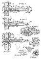
- a fastener 10 constitutes a first of the preferred embodiments of this invention.
- the fastener 10 is shown as used to mount a fixture 12 to a plasterboard wall 20.
- the wall 20 has a core 22 of friable material, such as gypsum plaster, between two paper layers, namely an outer layer 24 and an inner layer 26. As shown, a hole 28 accommodating the fastener 10 is drilled, via the fastener 10, through the wall 20. As explained below, the fastener 10 is used to drill such a hole.
- friable material such as gypsum plaster
- the fastener 10 is shown as coacting with a conventional screw 30 having a Phillips head 32, an elongate shank 34 with a threaded portion 36, and a pointed tip 38.
- the Phillips head 32 which is designed to coact with a conventional Phillips screwdriver, retains the fixture 12 when the screw 30 is driven into the fastener 10.
- the fastener 10 comprises a fastener body 40 and a toggle clamp 42.
- the fastener body 40 is die-cast from zinc and the toggle clamp 42 is stamped from sheet metal.
- zinc die-castings and sheet metal stampings are preferred, it is possible to mold the fastener body 40 and the toggle clamp 42 from a suitable plastic, such as reinforced polyolefin.
- the fastener body 40 defines an axis and has a head 44, a shank 46, a pair of elongate arms 48, and a drilling tip 50.
- the head 44 As compared to the shank 46, which has a relatively small cross section, the head has a relatively large cross section. Also, the head 44 is provided with a socket 52, by which the head 44 is adapted to coact with a conventional Phillips screwdriver.
- the fastener body 40 includes means for restricting rotational movement of the fastener body 40 relative to a wall, such as the wall 20, when the fastener 10 is mounted to the wall.
- the shank 46 has a threaded section 54 near the head 44.
- the threaded section 54 has a thread 56 with a profile suitable for a wall, such as the plasterboard wall 20, which comprises a friable material.
- the elongate arms 48 are integral with the shank 46 and extend axially from the shank 46.
- the arms 48 fit within an imaginary, cylindrical envelope having a cross section equal approximately to the cross section of the threaded section 54, except for the thread 56.
- the fastener body 40 has an unthreaded, axial bore 58, which extends through the head 44 and the shank 46, and which opens between the arms 48.
- the bore 58 is arranged to permit the shank 34 of the screw 30 to be axially moved into the bore 58.
- the shank 34 of the screw 30 may be axially pressed or rotatably and axially driven into the bore 58.
- the drilling tip 50 is integral with the elongate arms 48, which are spanned by the drilling tip 50.
- the drill tip 50 comprises a thin blade 60, which defines a centre cutter 62, and two outer cutters 64 with a cavity 66 between each of the outer cutters 64 and the central cutter 62.
- the central cutter 62 which extends axially beyond the outer cutters 64, is wedge-shaped, as shown.
- Each outer cutter 64 defines a helical cutting edge 68.
- the central cutter 62 penetrates the outer, paper layer 24 and the core 22 before the outer cutters 64 contact such layer 24. Thereupon, the helical cutting edges 68 of the outer cutters 64 cut cleanly through the outer, paper layer 24 with minimal risk of tearing such layer 24.
- the toggle clamp 42 is mounted to the fastener body 40 so as to permit pivotal movement of the toggle clamp 42 relative to the fastener body 40 between an insertion position and a toggle position, and so as to permit axial movement of the toggle clamp 42 relative to the fastener body 40.
- the toggle clamp 42 In the insertion position, in which the toggle clamp 42 is shown in Figures 1, 2 and 3, the toggle clamp 42 is aligned generally with the elongate arms 48.
- the toggle clamp 42 In the toggle position, in which the toggle clamp 42 is shown in Figure 4, the toggle clamp 42 is disposed generally at a right angle to the elongate arms 48.
- the screw 30 is used to pivot the toggle clamp 42 from the insertion position into the toggle position, after the fastener 10 has been inserted into the hole 28 with the toggle clamp 42 in the insertion position.
- Each arm 48 has an axially extending slot 70.
- the toggle clamp 42 has a pair of oppositely extending pintles 72.
- Each pintle 72 extends into a respective one of the slots 70 so as to mount the toggle clamp 42 pivotally to the fastener body 40 in such manner that the toggle clamp 42 is disposed between the arms 48 when the toggle clamp 42 is in the insertion position.
- the slots 70 and pintles 72 permit axial movement of the toggle clamp 42 relative to the fastener body 40.
- the toggle clamp 42 has a ramp 74, which is inclined, as shown, so as to define an angle of about 45° relative to the axis defined by the fastener body 40 when the toggle clamp 42 is in the insertion position.
- the ramp 74 is arranged to be axially engaged by the tip 38 of the screw 30 as the shank 34 of the screw 30 is moved into the bore 58 of the fastener body 40.
- the toggle clamp 42 has a thread-accepting aperture 76, which is adapted to form a threaded connection with the threaded portion 36 of the shank 34 of the screw 30, when the screw 30 is driven into the thread-accepting aperture 76, after the toggle clamp 42 has been pivoted into the toggle position.
- the threaded portion 36 is threaded into the toggle clamp 42.
- the thread-accepting aperture 76 may be complementarily threaded, so as to coact with the threaded portion 36.
- the toggle clamp 42 has a flange 78 near the thread-accepting aperture 76.
- the flange 78 is shaped so as to help to guide the threaded portion 36 of the shank 34 of the screw 30 into the thread-accepting aperture, as shown in Figure 4, in the toggle position of the toggle clamp 42.
- the fastener body 40 has a deformable tongue 80, which serves as means for preventing the toggle clamp 42 from pivoting freely from the insertion position into the toggle position in a given direction of pivotal movement.
- the tongue 80 includes a lip 81 adapted to be engaged by the tip 38 of the screw 30, as the shank 34 of the screw 30 is moved into the bore 58, so as to break away, thereby to permit pivotal movement of the toggle clamp 42 from the insertion position into the toggle position in the given direction. It is not necessary, however, for the tongue 80 to break away so as to permit such movement.
- the tongue 80 is formed with an internally extending tab 82.
- the tab 82 fits into an aperture 84 in the toggle clamp 42 and coacts with the aperture 84, so as to prevent axial movement of the toggle clamp 42 relative to the fastener body 40 before the tongue 82 is deformed.
- a connecting bridge 90 is formed integrally with the arms 48, so as to extend between the arms 48, in axially spaced relation to the shank 46.
- the bridge 90 constitutes means for preventing pivotal movement of the toggle clamp 42 from the insertion position into the toggle position in an opposite direction of pivotal movement. In Figures 2, 3, and 4, the opposite direction of pivotal movement is counterclockwise.
- a fastener 110 constitutes a second of the preferred embodiments of this invention.
- the fastener 110 is a blind fastener, which is capable of mounting a fixture 112 to a plasterboard wall 120.
- the plasterboard wall 120 is similar to the wall 20 and comprises a core 122 of friable material, such as gypsum plaster, between two paper layers, namely an outer layer 124 and an inner layer 126. As shown in Figures 10, 12, and 13, a hole 128 accommodating the fastener 110 is drilled through the wall 120. As explained below, the fastener 110 is used to drill such a hole.
- friable material such as gypsum plaster
- the fastener 110 is shown as coacting with a conventional screw 130 similar to the screw 30 described above.
- the screw 130 has a Phillips head 132, an elongate shank 134 with a threaded portion 136, and a pointed tip 138.
- the head 132 retains the fixture 112, as shown, when the screw 130 is driven into the fastener 110.
- the fastener 110 comprises a fastener body 140 and a toggle clamp 142.
- the fastener body 140 and the toggle clamp 142 are molded from a suitable plastic, such as reinforced polyolefin.
- plastic moldings are preferred, it is possible to die-cast the fastener body 140 from zinc and to stamp the toggle clamp 142 from sheet metal.
- the fastener body 140 defines an axis and has a head 144, a shank 146, a pair of elongate arms 148, and a connecting bridge 150.
- the head 144 As compared to the shank 146, which has a relatively small cross section, the head 144 has a relatively large cross section. Also, the head 144 is provided with a socket (not shown) which is similar to the socket 52 of the head 44 of the screw 30, and by which the head 144 is adapted to coact with a conventional Phillips screwdriver, such as the Phillips screwdriver D shown fragmentarily in Figures 9 and 10.
- a conventional Phillips screwdriver such as the Phillips screwdriver D shown fragmentarily in Figures 9 and 10.
- the fastener body 140 includes means for restricting rotational movement of the fastener body 140 relative to a wall, such as the wall 120, when the fastener 110 is mounted to the wall.
- the shank 146 has a threaded section 154 near the head 144.
- the threaded section 154 has a thread 156 with a profile suitable for a wall such as the plasterboard wall 120, which comprises a friable material.
- the elongate arms 148 are integral with the shank 146 and extend axially from the shank 146.
- the arms 148 fit within an imaginary, cylindrical envelope having a cross section equal approximately to the cross section of the threaded section 154, except for the thread 156.
- the bridge 150 which is integral with the arms 148, connects the arms 148 at their distal ends, in axially spaced relation to the threaded section 154.
- the fastener body 140 has an unthreaded, axial bore 158, which extends through the head 144 and the shank 146, and which opens between the arms 148.
- the bore 158 is arranged to permit the shank 134 of the screw 130 to be axially moved into the bore 158.
- the shank 134 may be axially pressed or rotatably and axially driven into the bore 158.
- the toggle clamp 142 is mounted to the fastener body 140 so as to permit pivotal movement of the toggle clamp 142 relative to the fastener body 140 between an insertion position and a toggle position, and so as to permit axial movement of the toggle clamp 142 relative to the fastener body 140.
- the toggle clamp 142 In the insertion position, in which the toggle clamp 142 is shown in Figures 9 through 12, the toggle clamp 142 is aligned generally with the elongate arms 148.
- the toggle clamp 142 In the toggle position, in which the toggle clamp 142 is shown in Figures 16 and 17, the toggle clamp 142 is disposed generally at a right angle to the elongate arms 148.
- the screw 130 is used to pivot the toggle clamp 142 from the insertion position into the toggle position, after the fastener 110 has been inserted into the hole 128 with the toggle clamp 142 in the insertion position.
- Each arm 148 has an axial extending slot 170.
- the toggle clamp 142 has a pair of oppositely extending pintles 172.
- Each pintle 172 extends into a respective one of the slots 170 so as to mount the toggle clamp 142 pivotally to the fastener body 140 in such manner that the toggle clamp 142 is disposed between the arms 148 when the toggle clamp 142 is in the insertion position.
- the slots 170 and pintles 172 permit axial movement of the toggle clamp 142 relative to the fastener body 140.
- the toggle clamp 142 has a ramp 174.
- the ramp 174 is arranged to be axially engaged by the tip 138 of the screw 130 as the shank 134 of the screw 130 is pressed into the bore 158 of the fastener body 140.
- the toggle clamp 142 has a thread-accepting aperture 176, which is adapted to form a threaded connection with the threaded portion 136 of the shank 134 of the screw 130, when the screw 130 is driven into the thread-accepting aperture 176, after the toggle clamp 142 has been pivoted into the toggle position.
- the thread-accepting aperture 176 is threaded complementarily, so as to coact with the threaded portion 136.
- the toggle clamp 142 is formed on one of its ends with an integral drilling tip 180.
- the drilling tip 180 comprises a thin blade 182 defining three wedge-shaped cutters, namely a central cutter 184 and two outer cutters 186 with a cavity 188 between each of the outer cutters 186 and the central cutter 184.
- the central cutter 184 extends axially beyond the outer cutters 186.
- the central cutter 184 penetrates the outer, paper layer 124, as shown in Figure 9, before the outer cutters 186 contact such layer 124. Thereupon, the outer cutters 186 cut through the outer, paper layer 124.
- the toggle clamp 142 may be integrally formed with a drilling tip similar to the drilling tip 50 of the first embodiment described above. Such a drilling tip may be more effective, as it tends to cut clearly through an outer, paper layer of a plasterboard wall with minimal risk of tearing such layer.
- the fastener body 140 and the toggle clamp 142 have a driving connection therebetween when the toggle clamp 142 is in the insertion position.
- the driving connection enables the fastener 110 to be rotatably and axially driven without imparting substantial stress to the pintles 172 when the drilling tip 180 on the toggle clamp 142 is used to drill a hole, such as the hole 128, in a wall, such as the wall 120.
- the driving connection is releasable when the ramp 174 is engaged by the screw 130 so as to permit pivotal movement of the toggle clamp 142 from the insertion position into the toggle position.
- the driving connection is defined by a non-circular plug 190 formed on one end of the toggle clamp 142, namely the end opposite to the drilling tip 180, and a socket 192 formed in the fastener body 140.
- the plug 190 and the socket 192 have non-circular cross-sections.
- the socket 192 conforms generally to the plug 90.
- the plug 190 is substantially square in cross-section and is formed with the ramp 174, which is defined by a groove formed in the plug 190.
- the socket 192 is substantially square in cross-section and with one open side and is defined by wall portions 194, 196, 198, which enclose the plug 190 on three sides when the toggle clamp 142 in the insertion position is pressed axially against the shank 146 of the fastener body 140.
- the socket 192 is adapted to receive the plug 190 when the toggle clamp 142 is in the insertion position.
- the wall portion 196 bridges the wall portions 194, 198, and extends axially for a short distance, as shown.
- the socket 192 is adapted to release the plug 192 when the toggle clamp 142 is displaced axially by a greater distance, after the ramp 174 has been engaged by the screw 130, so as to release the driving connection between the fastener body 140 and the toggle clamp 142.
Landscapes
- Engineering & Computer Science (AREA)
- General Engineering & Computer Science (AREA)
- Mechanical Engineering (AREA)
- Dowels (AREA)
- Drilling And Boring (AREA)
Claims (11)
- Organe de fixation (10) capable d'être enfoncé par perçage dans une paroi friable, telle qu'une plaque en plâtre, et d'être utilisé conjointement avec une vis (30) présentant une tête (32) et une tige allongée (34), pourvue d'une partie filetée, l'organe de fixation comprenant :(a) un corps d'organe de fixation (40) définissant un axe et présentant une tête (44), une tige (46) réalisée d'un seul tenant avec et s'étendant axialement depuis la tête (44) et au moins un bras allongé (48) d'un seul tenant avec et s'étendant axialement depuis la tige (46), le corps d'organe de fixation (40) ayant un alésage axial (58) qui traverse la tête (44) et la tige (46) et qui est, en utilisation, agencé de manière à permettre à la tige (34) d'une vis (30) d'être vissé en son sein;(b) un crampon articulé (42) monté pivotant sur le corps d'organe de fixation (40), entre une position d'insertion, dans laquelle le crampon articulé (42) est aligné globalement avec l'axe, et une position basculée, dans laquelle le crampon articulé (42) est disposé globalement à angle droit par rapport à l'axe, et de manière à permettre un mouvement axial du crampon articulé (42) par rapport au corps d'organe de fixation (40), le crampon articulé (42) présentant une ouverture taraudée (76) qui est, en utilisation, ménagée de manière à former une liaison filetée avec la partie filetée (36) de la tige (34) de la vis (30) et à permettre un mouvement axial du crampon articulé (42) par rapport au corps d'organe de fixation (40), lorsque la vis est entraînée dans l'ouverture taraudée (76) et que le crampon articulé (42) a pivoté dans la position basculée; et(c) une section filetée formée sur la tige (46), à proximité immédiate de la tête (32), la section filetée présentant un filetage (56, 156) servant à limiter tout mouvement de rotation du corps d'organe de fixation (40) par rapport à la paroi, lorsqu'il est monté dans la paroi; dans lequel l'organe de fixation (10) présente un bout de perçage (50) adapté de manière à percer un trou pour loger l'organe de fixation (10), lorsque le crampon articulé (42) se trouve en position d'insertion.
- Organe de fixation selon la revendication 1, dans lequel le crampon articulé (42) présente une rampe (74) qui, dans la position d'insertion du crampon articulé (42), est agencée de manière à être mise en contact axial avec la vis (30), lorsque la tige (34) de la vis (30) est entraînée dans l'alésage (58), de manière à faire pivoter le crampon articulé (42) pour passer de la position d'insertion à la position basculée.
- Organe de fixation selon la revendication 1 ou 2, dans lequel un couple de bras allongés (48) est inclus et le bout de perçage (80) est réalisé d'un seul tenant avec les bras allongés (48) et s'étend axialement au-delà du crampon articulé (42), dans les deux positions du crampon articulé (42).
- Organe de fixation selon l'une quelconque des revendications précédentes, dans lequel le corps d'organe de fixation (40) comprend un moyen déformable (80) servant à empêcher le crampon articulé (42) de pivoter librement de la position d'insertion à la position basculée, dans une direction du mouvement pivotant, le moyen (80) étant déformé, en utilisation, lorsque la tige (34) de la vis (30) est entraîné dans l'alésage (58), afin de permettre le pivotement du crampon articulé (42) pour passer de la position d'insertion à la position basculée dans la première direction, et dans lequel le corps d'organe de fixation (40) comprend un moyen supplémentaire (90) servant à empêcher tout mouvement pivotant du crampon articulé (42), pour passer de la position d'insertion à la position basculée, dans une direction opposée de mouvement pivotant.
- Organe de fixation selon la revendication 4, dans lequel le moyen déformable (80) comprend une lèvre (81) pouvant être mise au contact de la vis (30), lorsque la tige de la vis est entraînée dans l'alésage, afin de plier le moyen déformable (80) pour l'écarter du corps d'organe de fixation (40).
- Organe de fixation selon la revendication 1 ou 2, dans lequel le corps de l'organe de fixation (100) a deux bras allongés (148), le crampon (142) a deux extrémités opposées, le bout de perçage (180) étant d'un seul tenant avec l'une des extrémités opposées du crampon (142) et s'étendant axialement au-delà des bras (148) du corps (140) dans la position d'insertion du crampon (142).
- Organe de fixation selon la revendication 6, dans lequel le corps d'organe de fixation (140) et le crampon articulé (142) présentent des moyens coopérants (190, 192) servant à établir une liaison d'entraînement entre le corps d'organe de fixation (140) et le crampon articulé (142), lorsque le crampon articulé (142) se trouve en position d'insertion, la liaison d'entraînement permettant à l'organe de fixation d'être entraîné en rocation et en direction axiale sans appliquer de contrainte substantielle sur la liaison pivotante entre le corps d'organe de fixation (140) et le crampon articulé (142), lorsque le bout de perçage (180) est utilisé pour percer un trou dans la paroi, la liaison d'entraînement pouvant être libérée lorsque la rampe (174) est mise en contact avec la vis (130), de manière à permettre ensuite un mouvement pivotant du crampon articulé (142) pour passer de la position d'insertion à la position basculée.
- Organe de fixation selon la revendication 7, dans lequel les moyens coopérants servant à établir la liaison d'entraînement comprennent un obturateur (190) de forme non circulaire formé sur le crampon articulé (142) et des parties paroi (192) définissant une douille dans le corps d'organe de fixation (140), l'obturateur (190) étant formé sur l'extrémité du crampon articulé (142) opposée au bout de perçage (180), la douille se conformant globalement à l'obturateur et étant adaptée de manière à loger l'obturateur lorsque le crampon articulé se situe dans la position d'insertion et à libérer l'obturateur lorsque la rampe (174) est mise en contact avec la vis, de manière à permettre ensuite un mouvement pivotant du crampon articulé (142) pour passer de la position d'insertion à la position basculée.
- Organe de fixation selon l'une quelconque des revendications 2 à 8, dans lequel chacun des bras allongés (48, 148) présente une fente allongée (70, 170) et le crampon articulé (42, 142) présente un couple de pivots (72, 172) s'étendant de façon opposée, chacun d'entre eux s'étendant dans une fente respective parmi les fentes (70, 170), afin de monter le crampon articulé (42, 142) sur le corps d'organe de fixation (40, 140), de manière que, lorsque le crampon articulé (42, 142) se trouve en position d'insertion, il soit disposé entre les bras (48, 148), et de permettre un mouvement axial du crampon articulé (42, 142) par rapport au corps d'organe de fixation.
- Organe de fixation selon l'une quelconque des revendications précédentes, dans lequel le bout de perçage (80, 180) présente un organe de coupe (84, 184) central et deux organes de coupe (86, 186) extérieurs, avec une cavité (88, 89, 188, 189) entre chacun des organes de coupe (86, 186) extérieurs et l'organe de coupe (84, 184) central, l'organe de coupe (84, 184) central s'étendant axialement au-delà des organes de coupe (86, 186) extérieurs et chacun des organes de coupe (86, 186) extérieurs définit un bord de coupe (64) de forme globalement hélicoïdale.
- Organe de fixation selon l'une quelconque des revendications précédentes, dans lequel la tête (44, 144) de l'organe de fixation comprend des moyens (52, 152) pouvant être mis en contact d'entraînement avec un outil, pour enfoncer l'organe de fixation dans une paroi.
Applications Claiming Priority (2)
| Application Number | Priority Date | Filing Date | Title |
|---|---|---|---|
| US07/560,068 US5067864A (en) | 1990-07-27 | 1990-07-27 | Self-drilling fastener for plasterboard wall |
| US560068 | 2000-04-27 |
Publications (2)
| Publication Number | Publication Date |
|---|---|
| EP0468679A1 EP0468679A1 (fr) | 1992-01-29 |
| EP0468679B1 true EP0468679B1 (fr) | 1995-03-22 |
Family
ID=24236228
Family Applications (1)
| Application Number | Title | Priority Date | Filing Date |
|---|---|---|---|
| EP91306412A Expired - Lifetime EP0468679B1 (fr) | 1990-07-27 | 1991-07-15 | Elément de fixation auto-forant avec un garrot |
Country Status (10)
| Country | Link |
|---|---|
| US (1) | US5067864A (fr) |
| EP (1) | EP0468679B1 (fr) |
| JP (1) | JP3287587B2 (fr) |
| AU (1) | AU650276B2 (fr) |
| BR (1) | BR9102875A (fr) |
| CA (1) | CA2043912C (fr) |
| DE (1) | DE69108320T2 (fr) |
| ES (1) | ES2071224T3 (fr) |
| MX (1) | MX171815B (fr) |
| NZ (1) | NZ238494A (fr) |
Families Citing this family (36)
| Publication number | Priority date | Publication date | Assignee | Title |
|---|---|---|---|---|
| FR2684146B1 (fr) * | 1991-11-22 | 1994-02-11 | Prospection Inventions Technique | Cheville a bascule moulee d'une seule piece et son procede de moulage. |
| FR2701740B1 (fr) * | 1992-12-09 | 1995-08-11 | Plombelec | Dispositif de fixation de deux ou plusieurs materiaux. |
| US5413444A (en) * | 1994-01-06 | 1995-05-09 | Illinois Tool Works Inc. | Self-drilling fastener |
| AUPO629297A0 (en) * | 1997-04-21 | 1997-05-15 | W.A. Deutsher Pty Ltd | Threaded anchor |
| DE69827496T2 (de) * | 1997-07-24 | 2005-12-15 | Cobra Anchors Co. Ltd. | Verankerungseinheit mit schraubenspitze |
| US6250865B1 (en) | 1998-07-24 | 2001-06-26 | Cobra Anchors Co. Ltd | Screw tipped anchor assembly |
| US6435789B2 (en) * | 1999-12-21 | 2002-08-20 | Powers Fasteners | Self drilling swivel toggle anchor |
| JP4509308B2 (ja) * | 2000-01-28 | 2010-07-21 | 若井産業株式会社 | 回転ナット |
| US6382892B1 (en) | 2001-01-16 | 2002-05-07 | Dave C. Hempfling | Wall anchor with improved drilling tip |
| CA2420722A1 (fr) | 2003-03-04 | 2004-09-04 | Cobra Fixations Cie Ltee - Cobra Anchors Co. Ltd. | Crochet mural |
| FR2854211B1 (fr) * | 2003-04-24 | 2005-07-01 | Black & Decker Inc | Cheville d'ancrage pour vis, et ensemble constitue d'une telle cheville d'ancrage et d'une vis |
| US6884012B2 (en) * | 2003-09-04 | 2005-04-26 | Illinois Tool Works Inc. | Heavy duty toggle bolt fastener assembly, and method of installing and removing the same |
| US8764364B2 (en) | 2004-03-24 | 2014-07-01 | Illinois Tool Works Inc. | System and methods for wall and ceiling fastening |
| US20060083602A1 (en) * | 2004-10-18 | 2006-04-20 | Lemire Robert J | Blind fastening system |
| US7611316B2 (en) * | 2005-02-17 | 2009-11-03 | Illinois Tool Works Inc. | Heavy duty toggle bolt fastener for accommodating long screws and having properly positioned toggle nut component |
| CA2502008A1 (fr) | 2005-03-21 | 2006-09-21 | Cobra Fixations Cie Ltee - Cobra Anchors Co. Ltd. | Tige d'ancrage avec dispositif a bascule pour murs creux |
| CA2502044A1 (fr) | 2005-03-21 | 2006-09-21 | Cobra Fixations Cie Ltee. - Cobra Anchors Co. Ltd. | Tige d'ancrage pour piece de fixation |
| AU2005202700C1 (en) * | 2005-06-21 | 2006-07-06 | Glen Altoft | A Fastener |
| US20080132942A1 (en) * | 2006-12-04 | 2008-06-05 | Gregory Paul Mueller | Suture and method for using same |
| US7955392B2 (en) * | 2006-12-14 | 2011-06-07 | Warsaw Orthopedic, Inc. | Interspinous process devices and methods |
| GB0725363D0 (en) * | 2007-12-31 | 2008-02-06 | Pilon Jean | Hollow wall anchor |
| CA2643664A1 (fr) | 2008-10-30 | 2010-04-30 | Cobra Fixations Cie Ltee - Cobra Anchors Co. Ltd. | Crochet mural |
| NZ592887A (en) | 2008-11-18 | 2014-08-29 | Cobra Fixations Cie Ltee Cobra | Hanger for hollow walls |
| USD635843S1 (en) | 2009-10-30 | 2011-04-12 | Cobra Fixations Cie. Ltee.-Cobra Anchors Co., Ltd. | Wall-mounted hook |
| USD636256S1 (en) | 2009-11-18 | 2011-04-19 | Cobra Fixations Cie. Ltee.-Cobra Anchors Co. Ltd. | Wall-mounted hook |
| CA133911S (en) | 2010-01-27 | 2011-02-03 | Cobra Fixations Cie Ltée Cobra Anchors Co Ltd | Wall anchor |
| US8858143B2 (en) * | 2010-05-03 | 2014-10-14 | Black & Decker Inc. | Wall anchor |
| CN105432704B (zh) * | 2015-04-03 | 2018-05-11 | 九阳股份有限公司 | 一种出面快速的面条机 |
| US10180157B1 (en) * | 2015-12-07 | 2019-01-15 | Brunswick Corporation | Two-piece connector devices, connector assemblies and methods of use |
| WO2018144774A1 (fr) * | 2017-02-01 | 2018-08-09 | Theodore Garfield | Ancrage de canal métallique à force de maintien accrue |
| US10914335B2 (en) | 2017-11-21 | 2021-02-09 | Illinois Tool Works Inc. | Anchor assembly |
| US11486432B2 (en) * | 2018-11-29 | 2022-11-01 | The Hillman Group, Inc. | Anchor assembly with toggle |
| US11655837B2 (en) * | 2018-11-29 | 2023-05-23 | Tlie Hillman Group, Inc. | Anchor assembly with toggle |
| GB201820566D0 (en) * | 2018-12-17 | 2019-01-30 | Peckitt Darren Ashley | Hollow wall anchor |
| US12049911B2 (en) * | 2021-08-18 | 2024-07-30 | Delta Cycle Corporation | Anchor assembly |
| CN115013411B (zh) * | 2022-05-25 | 2024-05-10 | 宁波华力兴紧固件有限公司 | 一种高适应性防松脱紧固件 |
Citations (4)
| Publication number | Priority date | Publication date | Assignee | Title |
|---|---|---|---|---|
| US2908196A (en) * | 1957-07-25 | 1959-10-13 | Alex A Apfelzweig | Toggle bolt |
| US3385156A (en) * | 1966-03-30 | 1968-05-28 | Dan Polos Ind Inc | Self-drilling anchor bolt assembly |
| US3782238A (en) * | 1972-03-02 | 1974-01-01 | C Polos | Self-drilling toggle bolt assembly |
| US4047462A (en) * | 1976-03-29 | 1977-09-13 | Encor Limited | Toggle bolt |
Family Cites Families (13)
| Publication number | Priority date | Publication date | Assignee | Title |
|---|---|---|---|---|
| DE115373C (fr) * | ||||
| AT243480B (de) * | 1963-12-09 | 1965-11-10 | Artur Fischer | Aus einer längsgeschlitzten Hülse bestehender und mit einer Bohrkrone versehener Mauerdübel |
| US3927597A (en) * | 1974-08-30 | 1975-12-23 | Allan C Stults | Blind fastener |
| JPS5333073Y2 (fr) * | 1974-11-11 | 1978-08-15 | ||
| US4026186A (en) * | 1976-02-23 | 1977-05-31 | Illinois Tool Works Inc. | Self-drilling one-piece masonry anchor |
| DE2613192C2 (de) * | 1976-03-27 | 1984-02-02 | Textron Inc., Santa Ana, Calif. | Schraubensicherung |
| FR2352193A1 (fr) * | 1976-05-18 | 1977-12-16 | Meys Willy | Dispositif permettant le blocage reglable d'une piece mobile par rapport a un bati fixe |
| US4285264A (en) * | 1979-05-15 | 1981-08-25 | Coats & Clark, Inc. | General purpose hollow wall toggle fastener |
| DE2945663A1 (de) * | 1979-11-12 | 1981-05-21 | Hilti AG, 9494 Schaan | Selbstbohrduebel mit bohrkrone |
| JPS5736455A (en) * | 1980-08-15 | 1982-02-27 | Hitachi Ltd | Web driving device |
| US4822226A (en) * | 1983-08-08 | 1989-04-18 | Kennedy Arvest G | Wing nut retainer and extractor |
| EP0183882A1 (fr) * | 1984-12-04 | 1986-06-11 | Centre De Recherche Industrielle Du Quebec | Cheville à bascule |
| US4695030A (en) * | 1985-09-03 | 1987-09-22 | Fischer Jay P | Quick release clamp |
-
1990
- 1990-07-27 US US07/560,068 patent/US5067864A/en not_active Expired - Lifetime
-
1991
- 1991-06-05 CA CA002043912A patent/CA2043912C/fr not_active Expired - Lifetime
- 1991-06-11 NZ NZ238494A patent/NZ238494A/xx not_active IP Right Cessation
- 1991-06-21 MX MX026337A patent/MX171815B/es unknown
- 1991-07-09 BR BR919102875A patent/BR9102875A/pt not_active Application Discontinuation
- 1991-07-15 EP EP91306412A patent/EP0468679B1/fr not_active Expired - Lifetime
- 1991-07-15 DE DE69108320T patent/DE69108320T2/de not_active Expired - Lifetime
- 1991-07-15 ES ES91306412T patent/ES2071224T3/es not_active Expired - Lifetime
- 1991-07-22 JP JP20455591A patent/JP3287587B2/ja not_active Expired - Lifetime
- 1991-07-23 AU AU81242/91A patent/AU650276B2/en not_active Expired
Patent Citations (4)
| Publication number | Priority date | Publication date | Assignee | Title |
|---|---|---|---|---|
| US2908196A (en) * | 1957-07-25 | 1959-10-13 | Alex A Apfelzweig | Toggle bolt |
| US3385156A (en) * | 1966-03-30 | 1968-05-28 | Dan Polos Ind Inc | Self-drilling anchor bolt assembly |
| US3782238A (en) * | 1972-03-02 | 1974-01-01 | C Polos | Self-drilling toggle bolt assembly |
| US4047462A (en) * | 1976-03-29 | 1977-09-13 | Encor Limited | Toggle bolt |
Also Published As
| Publication number | Publication date |
|---|---|
| JP3287587B2 (ja) | 2002-06-04 |
| AU8124291A (en) | 1992-01-30 |
| EP0468679A1 (fr) | 1992-01-29 |
| DE69108320T2 (de) | 1995-08-17 |
| MX171815B (es) | 1993-11-16 |
| CA2043912A1 (fr) | 1992-01-28 |
| BR9102875A (pt) | 1992-02-11 |
| ES2071224T3 (es) | 1995-06-16 |
| AU650276B2 (en) | 1994-06-16 |
| JPH05321917A (ja) | 1993-12-07 |
| CA2043912C (fr) | 1996-01-09 |
| NZ238494A (en) | 1993-11-25 |
| DE69108320D1 (de) | 1995-04-27 |
| US5067864A (en) | 1991-11-26 |
Similar Documents
| Publication | Publication Date | Title |
|---|---|---|
| EP0468679A1 (fr) | Elément de fixation auto-forant avec un garrot | |
| US6186716B1 (en) | Anchor bolt | |
| EP2808567B1 (fr) | Ensemble d'ancrage pour murs creux comportant un élément à bascule | |
| EP1861626B2 (fr) | Ensemble d'ancrage pour piece de fixation | |
| US4601625A (en) | Self drilling threaded insert for drywall | |
| JP2520778B2 (ja) | 自己穿設型アンカ― | |
| KR100200991B1 (ko) | 나사 직경이 가변적인 벽 앵커 수용 파스너 | |
| US5449257A (en) | Self drilling anchor | |
| US4196883A (en) | Hollow wall fastener | |
| CA2352026C (fr) | Vis en forme de tariere pour cloisons seches | |
| US4285264A (en) | General purpose hollow wall toggle fastener | |
| EP1244877B1 (fr) | Ancrage | |
| AU749876B2 (en) | Screw tipped anchor assembly | |
| WO1992014935A1 (fr) | Vis de fixation | |
| GB2241549A (en) | Fastener anchor | |
| JP2511769B2 (ja) | 自己ドリルアンカ― | |
| EP0582374A2 (fr) | Cheville d'ancrage | |
| GB2389158A (en) | Anchorage | |
| HK1109188B (en) | Self-drilling hollow wall anchor | |
| HK1109188A1 (en) | Self-drilling hollow wall anchor |
Legal Events
| Date | Code | Title | Description |
|---|---|---|---|
| PUAI | Public reference made under article 153(3) epc to a published international application that has entered the european phase |
Free format text: ORIGINAL CODE: 0009012 |
|
| AK | Designated contracting states |
Kind code of ref document: A1 Designated state(s): BE DE ES FR GB IT SE |
|
| 17P | Request for examination filed |
Effective date: 19920717 |
|
| 17Q | First examination report despatched |
Effective date: 19930427 |
|
| GRAA | (expected) grant |
Free format text: ORIGINAL CODE: 0009210 |
|
| AK | Designated contracting states |
Kind code of ref document: B1 Designated state(s): BE DE ES FR GB IT SE |
|
| REF | Corresponds to: |
Ref document number: 69108320 Country of ref document: DE Date of ref document: 19950427 |
|
| ITF | It: translation for a ep patent filed | ||
| ET | Fr: translation filed | ||
| REG | Reference to a national code |
Ref country code: ES Ref legal event code: FG2A Ref document number: 2071224 Country of ref document: ES Kind code of ref document: T3 |
|
| PLBE | No opposition filed within time limit |
Free format text: ORIGINAL CODE: 0009261 |
|
| STAA | Information on the status of an ep patent application or granted ep patent |
Free format text: STATUS: NO OPPOSITION FILED WITHIN TIME LIMIT |
|
| 26N | No opposition filed | ||
| REG | Reference to a national code |
Ref country code: GB Ref legal event code: IF02 |
|
| PGFP | Annual fee paid to national office [announced via postgrant information from national office to epo] |
Ref country code: SE Payment date: 20040721 Year of fee payment: 14 |
|
| PGFP | Annual fee paid to national office [announced via postgrant information from national office to epo] |
Ref country code: ES Payment date: 20040809 Year of fee payment: 14 |
|
| PGFP | Annual fee paid to national office [announced via postgrant information from national office to epo] |
Ref country code: BE Payment date: 20040819 Year of fee payment: 14 |
|
| PG25 | Lapsed in a contracting state [announced via postgrant information from national office to epo] |
Ref country code: IT Free format text: LAPSE BECAUSE OF NON-PAYMENT OF DUE FEES;WARNING: LAPSES OF ITALIAN PATENTS WITH EFFECTIVE DATE BEFORE 2007 MAY HAVE OCCURRED AT ANY TIME BEFORE 2007. THE CORRECT EFFECTIVE DATE MAY BE DIFFERENT FROM THE ONE RECORDED. Effective date: 20050715 |
|
| PG25 | Lapsed in a contracting state [announced via postgrant information from national office to epo] |
Ref country code: SE Free format text: LAPSE BECAUSE OF NON-PAYMENT OF DUE FEES Effective date: 20050716 Ref country code: ES Free format text: LAPSE BECAUSE OF NON-PAYMENT OF DUE FEES Effective date: 20050716 |
|
| PG25 | Lapsed in a contracting state [announced via postgrant information from national office to epo] |
Ref country code: BE Free format text: LAPSE BECAUSE OF NON-PAYMENT OF DUE FEES Effective date: 20050731 |
|
| EUG | Se: european patent has lapsed | ||
| REG | Reference to a national code |
Ref country code: ES Ref legal event code: FD2A Effective date: 20050716 |
|
| BERE | Be: lapsed |
Owner name: *ILLINOIS TOOL WORKS INC. Effective date: 20050731 |
|
| PGFP | Annual fee paid to national office [announced via postgrant information from national office to epo] |
Ref country code: DE Payment date: 20100728 Year of fee payment: 20 Ref country code: FR Payment date: 20100805 Year of fee payment: 20 |
|
| PGFP | Annual fee paid to national office [announced via postgrant information from national office to epo] |
Ref country code: GB Payment date: 20100726 Year of fee payment: 20 |
|
| REG | Reference to a national code |
Ref country code: DE Ref legal event code: R071 Ref document number: 69108320 Country of ref document: DE |
|
| REG | Reference to a national code |
Ref country code: DE Ref legal event code: R071 Ref document number: 69108320 Country of ref document: DE |
|
| REG | Reference to a national code |
Ref country code: GB Ref legal event code: PE20 Expiry date: 20110714 |
|
| PG25 | Lapsed in a contracting state [announced via postgrant information from national office to epo] |
Ref country code: GB Free format text: LAPSE BECAUSE OF EXPIRATION OF PROTECTION Effective date: 20110714 |
|
| PG25 | Lapsed in a contracting state [announced via postgrant information from national office to epo] |
Ref country code: DE Free format text: LAPSE BECAUSE OF EXPIRATION OF PROTECTION Effective date: 20110716 |