EP0468698A1 - Elektrochemische Zelle enthaltender Apparat mit einer aussenliegenden Brennstoffmischdüse - Google Patents
Elektrochemische Zelle enthaltender Apparat mit einer aussenliegenden Brennstoffmischdüse Download PDFInfo
- Publication number
- EP0468698A1 EP0468698A1 EP91306527A EP91306527A EP0468698A1 EP 0468698 A1 EP0468698 A1 EP 0468698A1 EP 91306527 A EP91306527 A EP 91306527A EP 91306527 A EP91306527 A EP 91306527A EP 0468698 A1 EP0468698 A1 EP 0468698A1
- Authority
- EP
- European Patent Office
- Prior art keywords
- chamber
- fuel
- mixer
- reforming
- nozzle
- Prior art date
- Legal status (The legal status is an assumption and is not a legal conclusion. Google has not performed a legal analysis and makes no representation as to the accuracy of the status listed.)
- Granted
Links
Images

Classifications
-
- H—ELECTRICITY
- H01—ELECTRIC ELEMENTS
- H01M—PROCESSES OR MEANS, e.g. BATTERIES, FOR THE DIRECT CONVERSION OF CHEMICAL ENERGY INTO ELECTRICAL ENERGY
- H01M8/00—Fuel cells; Manufacture thereof
- H01M8/06—Combination of fuel cells with means for production of reactants or for treatment of residues
- H01M8/0606—Combination of fuel cells with means for production of reactants or for treatment of residues with means for production of gaseous reactants
- H01M8/0612—Combination of fuel cells with means for production of reactants or for treatment of residues with means for production of gaseous reactants from carbon-containing material
- H01M8/0625—Combination of fuel cells with means for production of reactants or for treatment of residues with means for production of gaseous reactants from carbon-containing material in a modular combined reactor/fuel cell structure
-
- H—ELECTRICITY
- H01—ELECTRIC ELEMENTS
- H01M—PROCESSES OR MEANS, e.g. BATTERIES, FOR THE DIRECT CONVERSION OF CHEMICAL ENERGY INTO ELECTRICAL ENERGY
- H01M8/00—Fuel cells; Manufacture thereof
- H01M8/06—Combination of fuel cells with means for production of reactants or for treatment of residues
-
- H—ELECTRICITY
- H01—ELECTRIC ELEMENTS
- H01M—PROCESSES OR MEANS, e.g. BATTERIES, FOR THE DIRECT CONVERSION OF CHEMICAL ENERGY INTO ELECTRICAL ENERGY
- H01M8/00—Fuel cells; Manufacture thereof
- H01M8/24—Grouping of fuel cells, e.g. stacking of fuel cells
-
- H—ELECTRICITY
- H01—ELECTRIC ELEMENTS
- H01M—PROCESSES OR MEANS, e.g. BATTERIES, FOR THE DIRECT CONVERSION OF CHEMICAL ENERGY INTO ELECTRICAL ENERGY
- H01M8/00—Fuel cells; Manufacture thereof
- H01M8/24—Grouping of fuel cells, e.g. stacking of fuel cells
- H01M8/241—Grouping of fuel cells, e.g. stacking of fuel cells with solid or matrix-supported electrolytes
- H01M8/2425—High-temperature cells with solid electrolytes
- H01M8/243—Grouping of unit cells of tubular or cylindrical configuration
-
- Y—GENERAL TAGGING OF NEW TECHNOLOGICAL DEVELOPMENTS; GENERAL TAGGING OF CROSS-SECTIONAL TECHNOLOGIES SPANNING OVER SEVERAL SECTIONS OF THE IPC; TECHNICAL SUBJECTS COVERED BY FORMER USPC CROSS-REFERENCE ART COLLECTIONS [XRACs] AND DIGESTS
- Y02—TECHNOLOGIES OR APPLICATIONS FOR MITIGATION OR ADAPTATION AGAINST CLIMATE CHANGE
- Y02E—REDUCTION OF GREENHOUSE GAS [GHG] EMISSIONS, RELATED TO ENERGY GENERATION, TRANSMISSION OR DISTRIBUTION
- Y02E60/00—Enabling technologies; Technologies with a potential or indirect contribution to GHG emissions mitigation
- Y02E60/30—Hydrogen technology
- Y02E60/50—Fuel cells
Definitions
- This invention relates to an electrochemical apparatus containing a plurality of electrochemical cells, each having an exterior fuel electrode, which can be contacted by a gaseous mixture of fresh feed fuel and recirculated spent fuel, which mixture contains water vapor and can pass through a reforming material prior to contacting the fuel electrodes; where recirculated, hot spent fuel heats the reforming material and the gaseous mixture, and fresh feed fuel and recirculated spent fuel can be mixed, at an ejector exterior to the body of the apparatus, with ejector and fresh feed fuel temperatures not exceeding 400°C.
- feed fuel either H 2 +CO, or previously reformed natural gas
- feed fuel either H 2 +CO, or previously reformed natural gas
- Spent fuel is combusted with spent oxidant in a separate chamber and then exits the apparatus.
- Natural gas (methane plus ethane, propane, butane and nitrogen) is a likely fuel for many of these fuel cell apparatus. This natural gas must be reformed, that is, converted to carbon monoxide and hydrogen, through the use of a catalyst and excess water vapor, prior to its utilization in the fuel cell.
- the reforming reaction is endothermic, requiring a supply of heat, and is best performed at temperatures close to 900°C. The heat required for reforming is a significant fraction of the excess heat that results from fuel cell operation.
- the use of recirculated spent fuel to provide water vapor and C0 2 forfresh feed fuel, by means of an ejector powered by the inlet fresh fuel pressure, has the potential to result in several problems.
- the ejector in the typical fuel cell apparatus is located directly in the hot fuel cell environment and is bathed by the hot recirculation gas stream, and the nozzle must be insulated or cooled to prevent carbon deposition from natural gas feed fuel, due to "cracking" which occurs at temperatures above about 400°C.
- the invention resides in an electrochemical apparatus having a fresh gaseous feed fuel inlet, gaseous feed oxidant inlet, hot gaseous spent fuel recirculation channel, separate combusted exhaust gas exit channel, a generator chamber containing a plurality of electrochemical cells, each cell having an exterior fuel electrode and an interior air electrode, a combustion chamber, and a reforming chamber containing a reforming material; characterized in that, the hot spent fuel recirculation channel, a portion of which is in contact with the outside of a mixer chamber, passes from the generator chamber to combine with the fresh feed fuel inlet at the entrance to the mixer chamber, and a mixer nozzle is located at the entrance to the mixer chamber, where the mixer chamber exit connects with the reforming chamber and reformed fuel entry ports connect the reforming chamber to the generator chamber, and where the mixer chamber and mixer nozzle are exterior to the main body of the apparatus and substantially spaced apart from the combustion chamberand the generatorchamber.
- the mixer nozzle can operate at a low temperature below 400°C.
- fuel electrode means that electrode in contact with fuel
- air electrode means that electrode in contact with air or oxygen
- spent fuel, oxidant, or air means partially reacted, low BTU fuel or partially reacted, depleted gaseous oxidant, or depleted air containing about 5% to 15% oxygen.
- spent fuel does not include the mixture of spent fuel combusted with spent oxidant or air, which mixture is herein defined as "combusted exhaust gas”.
- the relocation of the mixer, and the mixer nozzle (ejector nozzle) to a low-temperature position eliminates the need for forced cooling of the nozzle.
- the ducts which carry the recirculating spent fuel and which are in contact with the reforming chamber, and the ducts which carry the fuel mixture through the reforming material may be concentric, with heat conduction fins providing optimum heat exchange between the two gas streams. This heat exchange minimizes energy loss from the heat capacity of the hot extracted spent fuel, while allowing the nozzle temperature of the ejector, and therefore of the fresh fuel to remain below the 400°C limit above which carbon deposition has been observed.
- an electrochemical cell apparatus or generator 10 is shown containing two cell bundles 12 and 14, each bundle containing a plurality of parallel, axially elongated electrochemical cells 16, such as solid oxide fuel cells.
- the cells are located in generator compartment or section 22.
- Each cell has an exterior fuel electrode 18 covering its surface, shown dotted for the sake of clarity, an interior air electrode, and a solid oxide electrolyte between the electrodes (air electrode and electrolyte not shown).
- the air electrode is generally a doped ceramic of the perovskite family, for example, doped LaMn0 3
- the electrolyte is generally yttria stabilized zirconia
- the fuel electrode is generally a zirconia-nickel cermet material.
- a calcia stabilized zirconia support for the air electrode can also be used.
- the electrochemical cell apparatus 10 will operate with an interior temperature in the range of about 600°C to about 1,200°C.
- An outer housing 20 surrounds the entire apparatus.
- the housing is preferably comprised of a high temperature resistant metal such as Inconel.
- Thermal insulation 26, such as low density alumina is contained within the outer housing as shown. Penetrating the housing 20 and insulation 26 is fresh gaseous feed fuel inlet 28, the fresh feed fuel shown as F, and gaseous oxidant, such as air or oxygen, feed 30, as well as ports for electrical leads and the like, not shown.
- the generator chamber 22 extends between wall 32 and a porous barrier 34.
- the porous barrier 34 need not be a sealed structure.
- the porous barrier 34 is designed to allow spent fuel gas flow, indicated by arrows 36, from the generator chamber 22, operating at a pressure slightly above atmospheric, to the combustion chamber 24, operating at a sligtitly lower pressure, where the spent gas combines with spent oxidant 33, forming exhaust gas which passes through channel 45.
- High temperature, elongated, solid oxide electrolyte cells 16 extend between the combustion chamber 24 and the wall 32.
- the cells have open ends 44 in the combustion chamber 24, and closed ends in the generator chamber 22 near wall 32.
- Each individual cell generates approximately one volt on open circuit, and a plurality are electrically interconnected through conducting felts 40, usually nickel fiber metal, preferably in a series- parallel rectangular array.
- a gaseous oxidant such as air
- oxidant feed inlet 30 enters the oxidant feed conduits 42 at a temperature of approximately 500°C to 700°C, and a pressure above atmospheric, being optionally heated prior to entering the housing by conventional means, such as a heat exchanger coupled with a blower.
- the oxidant within the conduits, is passed through the combustion chamber 24, where it is further heated to a temperature of approximately 800°C to 900°C by the combusted exhaust gas.
- the oxidant then flows through the length of the oxidant circuit, through the conduits 42 which extend down the inside length of the fuel cells, being further heated to approximately 1,000°C, by virtue of absorbing most of the heat generated during the electrochemical reaction. A smaller fraction of the heat is absorbed by the fuel.
- the oxidant is discharged into the closed end bottom of the fuel cells 16.
- the oxidant within the fuel cells reverses direction, and electrochemically reacts at the inner air electrode along the inside active length of the cells, depleting somewhat in oxygen content as it approaches the open ends 44 of the cells.
- the depleted oxidant is then discharged into the combustion chamber 24 through the open cell ends 44, and is shown as spent oxidant streams 35.
- This spent oxidant combusts with depleted fuel, where part of the total depleted fuel passes through porous barrier 34 as shown by arrows 36, to form combusted exhaust gas 47, which exits the apparatus through combusted exhaust gas exit channels 45, finally exiting as exhaust gas E.
- the channels 45 can be made of a high temperature resistant metal or alloy.
- a gaseous fuel that has not yet been reformed such as a gaseous hydrocarbon, including hydrocarbons such as methane (CH 4 ), ethane (C 2 H 6 ), propane (C 3 H 8 ), and the like, vaporized petroleum fractions such as naphtha, and alcohols, such as ethyl alcohol (C 2 H 5 0H), and the like, and natural gas, typically a mixture of 858 methane and 10% ethane with a balance of propane, butane and nitrogen, can be used.
- a gaseous hydrocarbon including hydrocarbons such as methane (CH 4 ), ethane (C 2 H 6 ), propane (C 3 H 8 ), and the like
- vaporized petroleum fractions such as naphtha
- alcohols such as ethyl alcohol (C 2 H 5 0H)
- natural gas typically a mixture of 858 methane and 10% ethane with a balance of propane, butane and nitrogen
- a major portion of the hot gaseous spent fuel formed along the axial length of the cells 16 passes to at least one hot spent fuel recirculation channel 46, which can be made of a high temperature resistant metal or alloy.
- Another portion of the hot spent fuel passes into combustion chamber 24, shown as arrows 36, as previously described, to combust with spent air, shown as arrow 35, and preheat the fresh oxidant feed.
- the hot spent fuel exit channel 46 passes from the generator chamber 22 to feed into and combine with the fresh feed fuel inlet at the entrance to the mixer means or chamber 52, at a mixer nozzle 50, which can be of any type known in the art, for example, an ejector, jet pump, aspirator, or the like.
- This mixer nozzle 50 is located at the entrance to the mixer-diffuser chamber 52. This allows recirculation of the portion of the spent fuel fed into channel 46 to mix with the fresh feed fuel at mixer nozzle 50, to provide a reformable fuel mixture of the two gases, shown by arrows 51.
- the geometry of the ejector/mixer is further designed such, that the dynamic energy of the fuel at the nozzle 50 is effectively converted to an elevated pressure at entrance to the reforming chamber 54. This is preferably accomplished by a diffuser, the cross-sectional area of which gets larger as it proceeds from its entrance near nozzle 50, to the reforming chamber 54, in one fashion as shown.
- the reformable fuel mixture 51 will contain at least water vapor (steam) and usually also H 2 , CO, and CO 2 , all contributed by the spent fuel that enters mixerdiffuser chamber 52.
- the volume ratio of spent fuel to fresh feed fuel will be adjusted by the velocity of the fresh feed fuel input so that approximately 2 volumes to 5 volumes of water vapor and C0 2 are added to each volume of fresh feed fuel.
- the presence of water vapor plus a reforming catalyst, most commonly Ni, allows conversion of gaseous hydrocarbons to CO+H 2 , by the reaction: A similar fuel conversion reaction to H 2 and CO is accomplished with C0 2 in place of water vapor.
- the reformable fuel mixture 51 then passes from the mixer chamber exit into and through a cylindrical reforming means or chamber 54 containing reforming material 56, such as nickel, or the like, or other well-known useful reforming material for fuel gas.
- reforming material 56 such as nickel, or the like, or other well-known useful reforming material for fuel gas.
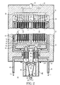
- the design shown in Figure 2 for the reforming chamber 54 is an annular, concentric, vessel surrounding the hot spent fuel inlet 46'. This design is generally used when combusted exhaust gas from channel 45 is channeled to contact the reforming chamber and entails a crossover of gases from chambers 46' and 52.
- the reformed fuel mixture shown by arrows 58, after having just passed from the mixer-diffuser chamber 52, upward into the reforming chamber 54, and through the reforming material 56, passes directly upward through a series of reformed fuel entry ports 59, which connect the reforming chamber to the generator chamber 22, and then into the generator chamber of the apparatus.
- hot spent fuel from channel 46 reaches channel 46' at a temperature of approximately 1,000°C.
- Channel 46' in contact with the reforming chamber 54, allows a means of heat transfer between hot gas in that channel and chamber 54. This reduces the spent fuel temperature and provides heat for the endothermic reforming reaction.
- complete reforming of the fuel is not necessary since some internal reforming of the reformable fuel mixture by the nickel fiber felts 40, or on the nickel cermet surface 18 of the fuel cells within the generator chamber 22, can be utilized to keep the amount of reforming material 56 relatively small, and allow internal reformer 54 inclusion within the apparatus 10 if desirable.
- spent fuel passes from channel 46', down, around, and in contact with the outside of mixer- diffuser chamber 52 with a further loss of heat which is transferred to the reformable fuel mixture 51 as it approaches the reformer 56.
- the spent fuel within nozzle feed channel 60 which is an extension of channel 46', is fed to contact the mixer-diffuser chamber 52, which chamber has upward flowing reformable fuel mixture 51 therein, allowing heat transfer from the channel 60 and hot spent fuel to the mixer chamber and gas therein.
- This reformable fuel mixture 52 continues upward toward the reforming chamber and generator chamber.
- the temperature of the spent fuel drops from approximately 1,000°C at the entrance to channel 46', to a sufficiently low temperature as it approaches the nozzle 50 such that the fresh fuel in the mixer chamber 52 will not exceed 400°C.
- the combusted exhaust gas E in separate channels 45 as shown in the drawing passes out of the apparatus at approximately 800°C; or if the combusted exhaust gas is first used to provide additional heat for the reformer, as shown in Figure 2, it would exit at about 650°C.
- the entire mixer nozzle-mixer chamber subassembly 62 is essentially, exteriorly bolted onto the electrochemical apparatus 10.
- the mixer-diffuser chamber 52 and mixer nozzle 50 while part of the electrochemical apparatus, are exterior to the main body of the apparatus and substantially spaced apart from the rest of the apparatus, and the combustion chamber 24 and the generator chamber 22.
- the mixer nozzle 50 can operate at below approximately 400°C, which would be the approximate temperature at the mixer nozzle 50 and entrance to the mixer chamber 52.
- the mixer nozzle is extended by gaseous component ducts or channels to a position remote from the high-temperature active generating and combusting region of the apparatus, and can operate at a sufficiently low temperature to prevent carbon deposition.
- the gaseous component ducts or channels are coupled or arranged in a manner to facilitate heat exchange from hot spent fuel to a reformable fuel mixture, thus conserving much of the thermal energy of the recirculating fuel gas, while maintaining a low nozzle temperature to prevent carbon deposition.
- This combination, coupled with reformer contact allows utilization of the high temperature spent fuel gas to provide the endothermic energy requirement of the reforming reaction.
- the primary gas seals can be extended and located in a colder region and allow ease of disassembly and replacement of the subassembly 62 as a cartridge unit.
Landscapes
- Life Sciences & Earth Sciences (AREA)
- Engineering & Computer Science (AREA)
- Manufacturing & Machinery (AREA)
- Sustainable Development (AREA)
- Sustainable Energy (AREA)
- Chemical & Material Sciences (AREA)
- Chemical Kinetics & Catalysis (AREA)
- Electrochemistry (AREA)
- General Chemical & Material Sciences (AREA)
- Fuel Cell (AREA)
- Devices For Medical Bathing And Washing (AREA)
Applications Claiming Priority (2)
| Application Number | Priority Date | Filing Date | Title |
|---|---|---|---|
| US07/559,103 US5169730A (en) | 1990-07-25 | 1990-07-25 | Electrochemical cell apparatus having an exterior fuel mixer nozzle |
| US559103 | 1990-07-25 |
Publications (2)
| Publication Number | Publication Date |
|---|---|
| EP0468698A1 true EP0468698A1 (de) | 1992-01-29 |
| EP0468698B1 EP0468698B1 (de) | 1995-10-11 |
Family
ID=24232279
Family Applications (1)
| Application Number | Title | Priority Date | Filing Date |
|---|---|---|---|
| EP91306527A Expired - Lifetime EP0468698B1 (de) | 1990-07-25 | 1991-07-18 | Elektrochemische Zelle enthaltender Apparat mit einer aussenliegenden Brennstoffmischdüse |
Country Status (8)
| Country | Link |
|---|---|
| US (1) | US5169730A (de) |
| EP (1) | EP0468698B1 (de) |
| JP (1) | JP2965272B2 (de) |
| KR (1) | KR100264296B1 (de) |
| CA (1) | CA2041726C (de) |
| DE (1) | DE69113707T2 (de) |
| ES (1) | ES2080258T3 (de) |
| NO (1) | NO306008B1 (de) |
Cited By (7)
| Publication number | Priority date | Publication date | Assignee | Title |
|---|---|---|---|---|
| EP0677327A1 (de) * | 1994-02-18 | 1995-10-18 | Westinghouse Electric Corporation | Katalytisches material für die Reformierung von Kohlenwasserstoffen und ihre Konfiguration |
| GB2294577A (en) * | 1994-10-28 | 1996-05-01 | Mtu Friedrichshafen Gmbh | Fuel cell stack arrangement wherein the off-gas stream from the fuel cells is used for heating the reformer |
| WO2003038934A1 (fr) * | 2001-11-01 | 2003-05-08 | Osaka Gas Co., Ltd. | Systeme de pile a combustible |
| WO2003071624A3 (en) * | 2002-02-20 | 2004-01-15 | Acumentrics Corp | Fuel cell stacking and sealing |
| WO2008023751A1 (en) * | 2006-08-25 | 2008-02-28 | Honda Motor Co., Ltd. | Fuel cell and fuel cell module |
| US7416802B2 (en) | 2000-05-22 | 2008-08-26 | Acumentrics Corporation | Electrode-supported solid state electrochemical cell |
| AU2003201391B2 (en) * | 2002-01-31 | 2008-11-06 | Ceramic Fuel Cells Limited | Thermal managment of fuel cells |
Families Citing this family (100)
| Publication number | Priority date | Publication date | Assignee | Title |
|---|---|---|---|---|
| DE4419281C1 (de) * | 1994-06-01 | 1995-12-14 | Daimler Benz Ag | Hochtemperaturbatterie |
| US5498487A (en) * | 1994-08-11 | 1996-03-12 | Westinghouse Electric Corporation | Oxygen sensor for monitoring gas mixtures containing hydrocarbons |
| US5750278A (en) * | 1995-08-10 | 1998-05-12 | Westinghouse Electric Corporation | Self-cooling mono-container fuel cell generators and power plants using an array of such generators |
| US5733675A (en) * | 1995-08-23 | 1998-03-31 | Westinghouse Electric Corporation | Electrochemical fuel cell generator having an internal and leak tight hydrocarbon fuel reformer |
| DE59507707D1 (de) * | 1995-12-19 | 2000-03-02 | Sulzer Hexis Ag Winterthur | Vorrichtung mit Brennstoffzellen |
| US5573867A (en) * | 1996-01-31 | 1996-11-12 | Westinghouse Electric Corporation | Purge gas protected transportable pressurized fuel cell modules and their operation in a power plant |
| US5741605A (en) * | 1996-03-08 | 1998-04-21 | Westinghouse Electric Corporation | Solid oxide fuel cell generator with removable modular fuel cell stack configurations |
| RU2121191C1 (ru) * | 1996-04-01 | 1998-10-27 | Российский федеральный ядерный центр - Всероссийский научно-исследовательский институт технической физики | Электрохимический генератор |
| US7066973B1 (en) | 1996-08-26 | 2006-06-27 | Nuvera Fuel Cells | Integrated reformer and shift reactor |
| US6440594B1 (en) * | 1999-06-17 | 2002-08-27 | California Institute Of Technology | Aerosol feed direct methanol fuel cell |
| US6656623B2 (en) * | 2001-02-15 | 2003-12-02 | Siemens Westinghouse Power Corporation | Low-cost atmospheric SOFC power generation system |
| US6764784B2 (en) * | 2001-09-17 | 2004-07-20 | Siemens Westinghouse Power Corporation | Standard package design for both atmospheric and pressurized SOFC power generation system |
| US6689499B2 (en) | 2001-09-17 | 2004-02-10 | Siemens Westinghouse Power Corporation | Pressurized solid oxide fuel cell integral air accumular containment |
| US6936367B2 (en) * | 2002-01-16 | 2005-08-30 | Alberta Research Council Inc. | Solid oxide fuel cell system |
| US7736772B2 (en) * | 2002-02-14 | 2010-06-15 | Alberta Research Council, Inc. | Tubular solid oxide fuel cell stack |
| US7067208B2 (en) * | 2002-02-20 | 2006-06-27 | Ion America Corporation | Load matched power generation system including a solid oxide fuel cell and a heat pump and an optional turbine |
| JP2006502938A (ja) | 2002-06-13 | 2006-01-26 | ヌヴェラ フューエル セルズ インコーポレイテッド | 優先的酸化反応装置の温度調整 |
| US7118818B2 (en) * | 2002-10-01 | 2006-10-10 | Rolls-Royce Plc | Solid oxide fuel cell system |
| US6821663B2 (en) * | 2002-10-23 | 2004-11-23 | Ion America Corporation | Solid oxide regenerative fuel cell |
| US7282291B2 (en) | 2002-11-25 | 2007-10-16 | California Institute Of Technology | Water free proton conducting membranes based on poly-4-vinylpyridinebisulfate for fuel cells |
| US6989209B2 (en) * | 2002-12-27 | 2006-01-24 | General Electric Company | Power generation method |
| US7045238B2 (en) * | 2003-03-24 | 2006-05-16 | Ion America Corporation | SORFC power and oxygen generation method and system |
| US6924053B2 (en) * | 2003-03-24 | 2005-08-02 | Ion America Corporation | Solid oxide regenerative fuel cell with selective anode tail gas circulation |
| US7575822B2 (en) | 2003-04-09 | 2009-08-18 | Bloom Energy Corporation | Method of optimizing operating efficiency of fuel cells |
| US7482078B2 (en) * | 2003-04-09 | 2009-01-27 | Bloom Energy Corporation | Co-production of hydrogen and electricity in a high temperature electrochemical system |
| US7878280B2 (en) * | 2003-04-09 | 2011-02-01 | Bloom Energy Corporation | Low pressure hydrogen fueled vehicle and method of operating same |
| US7364810B2 (en) | 2003-09-03 | 2008-04-29 | Bloom Energy Corporation | Combined energy storage and fuel generation with reversible fuel cells |
| US7150927B2 (en) * | 2003-09-10 | 2006-12-19 | Bloom Energy Corporation | SORFC system with non-noble metal electrode compositions |
| US7309537B2 (en) * | 2003-09-18 | 2007-12-18 | Ballard Power Systems Inc. | Fuel cell system with fluid stream recirculation |
| US7387850B2 (en) * | 2003-12-31 | 2008-06-17 | General Electric Company | Oxidant and fuel distribution for a fuel cell assembly |
| US7422810B2 (en) * | 2004-01-22 | 2008-09-09 | Bloom Energy Corporation | High temperature fuel cell system and method of operating same |
| US7364812B2 (en) * | 2004-03-19 | 2008-04-29 | Pittsburgh Electric Engines, Inc. | Multi-function solid oxide fuel cell bundle and method of making the same |
| MY151832A (en) * | 2004-06-28 | 2014-07-14 | Osaka Gas Co Ltd | Reformed gas production method and reformed gas production apparatus |
| JP2008507828A (ja) * | 2004-07-28 | 2008-03-13 | セラミック・フューエル・セルズ・リミテッド | 燃料電池システム |
| WO2006055442A2 (en) * | 2004-11-15 | 2006-05-26 | William Stanton | Uninterruptible power supply system |
| US20060147771A1 (en) * | 2005-01-04 | 2006-07-06 | Ion America Corporation | Fuel cell system with independent reformer temperature control |
| US7514166B2 (en) * | 2005-04-01 | 2009-04-07 | Bloom Energy Corporation | Reduction of SOFC anodes to extend stack lifetime |
| US7524572B2 (en) * | 2005-04-07 | 2009-04-28 | Bloom Energy Corporation | Fuel cell system with thermally integrated combustor and corrugated foil reformer |
| US8709674B2 (en) * | 2005-04-29 | 2014-04-29 | Alberta Research Council Inc. | Fuel cell support structure |
| US20060251934A1 (en) * | 2005-05-09 | 2006-11-09 | Ion America Corporation | High temperature fuel cell system with integrated heat exchanger network |
| US7858256B2 (en) | 2005-05-09 | 2010-12-28 | Bloom Energy Corporation | High temperature fuel cell system with integrated heat exchanger network |
| US8691462B2 (en) * | 2005-05-09 | 2014-04-08 | Modine Manufacturing Company | High temperature fuel cell system with integrated heat exchanger network |
| US7700210B2 (en) * | 2005-05-10 | 2010-04-20 | Bloom Energy Corporation | Increasing thermal dissipation of fuel cell stacks under partial electrical load |
| JP5542333B2 (ja) * | 2005-07-25 | 2014-07-09 | ブルーム エナジー コーポレーション | 電気化学アノードの排気のリサイクルを行う燃料電池システム |
| US7520916B2 (en) * | 2005-07-25 | 2009-04-21 | Bloom Energy Corporation | Partial pressure swing adsorption system for providing hydrogen to a vehicle fuel cell |
| US20070017368A1 (en) * | 2005-07-25 | 2007-01-25 | Ion America Corporation | Gas separation method and apparatus using partial pressure swing adsorption |
| US9911989B2 (en) * | 2005-07-25 | 2018-03-06 | Bloom Energy Corporation | Fuel cell system with partial recycling of anode exhaust |
| US7591880B2 (en) * | 2005-07-25 | 2009-09-22 | Bloom Energy Corporation | Fuel cell anode exhaust fuel recovery by adsorption |
| JP5109242B2 (ja) * | 2005-08-09 | 2012-12-26 | トヨタ自動車株式会社 | 燃料電池に燃料ガスを供給する装置と燃料電池システム |
| US7659022B2 (en) | 2006-08-14 | 2010-02-09 | Modine Manufacturing Company | Integrated solid oxide fuel cell and fuel processor |
| US9190693B2 (en) | 2006-01-23 | 2015-11-17 | Bloom Energy Corporation | Modular fuel cell system |
| US8822094B2 (en) * | 2006-04-03 | 2014-09-02 | Bloom Energy Corporation | Fuel cell system operated on liquid fuels |
| WO2007117406A2 (en) * | 2006-04-03 | 2007-10-18 | Bloom Energy Corporation | Fuel cell system and balance of plant configuration |
| US8241801B2 (en) | 2006-08-14 | 2012-08-14 | Modine Manufacturing Company | Integrated solid oxide fuel cell and fuel processor |
| EP2064766A4 (de) * | 2006-09-06 | 2010-09-29 | Bloom Energy Corp | Flexible brennstoffzellensystemkonfiguration zur handhabung von mehreren brennstoffen |
| US7846600B2 (en) * | 2006-09-21 | 2010-12-07 | Bloom Energy Corporation | Adaptive purge control to prevent electrode redox cycles in fuel cell systems |
| US7968245B2 (en) * | 2006-09-25 | 2011-06-28 | Bloom Energy Corporation | High utilization stack |
| US10615444B2 (en) | 2006-10-18 | 2020-04-07 | Bloom Energy Corporation | Anode with high redox stability |
| US8748056B2 (en) | 2006-10-18 | 2014-06-10 | Bloom Energy Corporation | Anode with remarkable stability under conditions of extreme fuel starvation |
| WO2008051368A2 (en) * | 2006-10-23 | 2008-05-02 | Bloom Energy Corporation | Dual function heat exchanger for start-up humidification and facility heating in sofc system |
| US7393603B1 (en) * | 2006-12-20 | 2008-07-01 | Bloom Energy Corporation | Methods for fuel cell system optimization |
| US20090214905A1 (en) * | 2007-01-08 | 2009-08-27 | California Institute Of Technology | Direct methanol fuel cell operable with neat methanol |
| US7883803B2 (en) * | 2007-03-30 | 2011-02-08 | Bloom Energy Corporation | SOFC system producing reduced atmospheric carbon dioxide using a molten carbonated carbon dioxide pump |
| US7833668B2 (en) * | 2007-03-30 | 2010-11-16 | Bloom Energy Corporation | Fuel cell system with greater than 95% fuel utilization |
| US20080261099A1 (en) | 2007-04-13 | 2008-10-23 | Bloom Energy Corporation | Heterogeneous ceramic composite SOFC electrolyte |
| WO2008150524A2 (en) | 2007-06-04 | 2008-12-11 | Bloom Energy Corporation | Structure for high temperature fuel cell system start up and shutdown |
| US8920997B2 (en) | 2007-07-26 | 2014-12-30 | Bloom Energy Corporation | Hybrid fuel heat exchanger—pre-reformer in SOFC systems |
| US8852820B2 (en) | 2007-08-15 | 2014-10-07 | Bloom Energy Corporation | Fuel cell stack module shell with integrated heat exchanger |
| CN105206847B (zh) | 2007-11-13 | 2018-02-09 | 博隆能源股份有限公司 | 针对较长寿命和较高电力设计的电解质支撑型电池 |
| US9246184B1 (en) | 2007-11-13 | 2016-01-26 | Bloom Energy Corporation | Electrolyte supported cell designed for longer life and higher power |
| US8197976B2 (en) * | 2008-01-04 | 2012-06-12 | Protonex Technology Corporation | Solid oxide fuel cell systems with hot zones and two-stage tail gas combustors |
| WO2009105191A2 (en) | 2008-02-19 | 2009-08-27 | Bloom Energy Corporation | Fuel cell system containing anode tail gas oxidizer and hybrid heat exchanger/reformer |
| ATE540443T1 (de) * | 2008-05-30 | 2012-01-15 | Corning Inc | Festoxidbrennstoffzellensysteme mit wärmetauschern |
| US8968958B2 (en) | 2008-07-08 | 2015-03-03 | Bloom Energy Corporation | Voltage lead jumper connected fuel cell columns |
| US9287571B2 (en) * | 2008-07-23 | 2016-03-15 | Bloom Energy Corporation | Operation of fuel cell systems with reduced carbon formation and anode leading edge damage |
| US8617763B2 (en) | 2009-08-12 | 2013-12-31 | Bloom Energy Corporation | Internal reforming anode for solid oxide fuel cells |
| EP2474063B1 (de) * | 2009-09-02 | 2017-04-12 | Bloom Energy Corporation | Mehrstrom-wärmetauscher für ein brennstoffzellensystem |
| AU2011209829C1 (en) | 2010-01-26 | 2016-09-01 | Bloom Energy Corporation | Phase stable doped zirconia electrolyte compositions with low degradation |
| US8440362B2 (en) | 2010-09-24 | 2013-05-14 | Bloom Energy Corporation | Fuel cell mechanical components |
| US8586252B2 (en) | 2010-11-18 | 2013-11-19 | Acumentrics Corporation | Integral reactor system and method for fuel cells |
| EP2661782B1 (de) | 2011-01-06 | 2018-10-03 | Bloom Energy Corporation | Sofc-heizbehälter-komponenten |
| AU2011379051A1 (en) * | 2011-10-14 | 2014-05-01 | Haldor Topsoe A/S | Stack assembly |
| CN104798237B (zh) | 2012-11-20 | 2018-12-14 | 博隆能源股份有限公司 | 经掺杂氧化钪稳定的氧化锆电解质组合物 |
| US9755263B2 (en) | 2013-03-15 | 2017-09-05 | Bloom Energy Corporation | Fuel cell mechanical components |
| US10109867B2 (en) | 2013-06-26 | 2018-10-23 | Upstart Power, Inc. | Solid oxide fuel cell with flexible fuel rod support structure |
| TWI638483B (zh) | 2013-10-23 | 2018-10-11 | 美商博隆能源股份有限公司 | 用於燃料電池系統之陽極復熱器及其操作方法 |
| TWI663771B (zh) | 2014-02-12 | 2019-06-21 | 美商博隆能源股份有限公司 | 多個燃料電池和電力電子供給負載並聯以允許整合電化學阻抗頻譜(eis)之燃料電池系統之結構及方法 |
| KR102320128B1 (ko) | 2014-10-07 | 2021-11-02 | 프로토넥스 테크놀로지 코퍼레이션 | Sofc-전도 |
| US10096840B1 (en) | 2014-12-15 | 2018-10-09 | Bloom Energy Corporation | High temperature air purge of solid oxide fuel cell anode electrodes |
| US10651496B2 (en) | 2015-03-06 | 2020-05-12 | Bloom Energy Corporation | Modular pad for a fuel cell system |
| US10347930B2 (en) | 2015-03-24 | 2019-07-09 | Bloom Energy Corporation | Perimeter electrolyte reinforcement layer composition for solid oxide fuel cell electrolytes |
| CN108370043B (zh) | 2015-10-20 | 2021-09-07 | 新兴电力公司 | 改进的cpox燃料重整器和sofc系统 |
| US10790523B2 (en) | 2015-10-20 | 2020-09-29 | Upstart Power, Inc. | CPOX reactor control system and method |
| CA3072005C (en) | 2016-08-11 | 2023-09-19 | Upstart Power, Inc. | Sofc with thermally conductive pathways |
| US10361442B2 (en) | 2016-11-08 | 2019-07-23 | Bloom Energy Corporation | SOFC system and method which maintain a reducing anode environment |
| US12266835B2 (en) | 2017-08-28 | 2025-04-01 | Bloom Energy Corporation | SOFC including redox-tolerant anode electrode and method of making the same |
| US10680251B2 (en) | 2017-08-28 | 2020-06-09 | Bloom Energy Corporation | SOFC including redox-tolerant anode electrode and system including the same |
| US11398634B2 (en) | 2018-03-27 | 2022-07-26 | Bloom Energy Corporation | Solid oxide fuel cell system and method of operating the same using peak shaving gas |
| US12374709B2 (en) | 2019-08-14 | 2025-07-29 | Upstart Power, Inc. | Sofc-conduction |
| KR20230000972A (ko) | 2021-06-25 | 2023-01-03 | 블룸 에너지 코퍼레이션 | 연료 전지 시스템의 건전성 및 성능을 최대화하기 위한 가변적이고 예측할 수 없는 가스 조성 변화의 처리 |
Citations (4)
| Publication number | Priority date | Publication date | Assignee | Title |
|---|---|---|---|---|
| US3718506A (en) * | 1971-02-22 | 1973-02-27 | Bbc Brown Boveri & Cie | Fuel cell system for reacting hydrocarbons |
| EP0076019A1 (de) * | 1981-09-29 | 1983-04-06 | Westinghouse Electric Corporation | Brennstoffzellengenerator und Verfahren zum Betrieb desselben |
| US4729931A (en) * | 1986-11-03 | 1988-03-08 | Westinghouse Electric Corp. | Reforming of fuel inside fuel cell generator |
| EP0328812A1 (de) * | 1988-02-16 | 1989-08-23 | Westinghouse Electric Corporation | Elektrochemische Generatoren von rechteckiger Form mit Heizung in den Eckbereichen |
Family Cites Families (2)
| Publication number | Priority date | Publication date | Assignee | Title |
|---|---|---|---|---|
| US4490444A (en) * | 1980-12-22 | 1984-12-25 | Westinghouse Electric Corp. | High temperature solid electrolyte fuel cell configurations and interconnections |
| US4395468A (en) * | 1980-12-22 | 1983-07-26 | Westinghouse Electric Corp. | Fuel cell generator |
-
1990
- 1990-07-25 US US07/559,103 patent/US5169730A/en not_active Expired - Lifetime
-
1991
- 1991-05-02 CA CA002041726A patent/CA2041726C/en not_active Expired - Lifetime
- 1991-06-25 NO NO912471A patent/NO306008B1/no not_active IP Right Cessation
- 1991-07-11 JP JP3197076A patent/JP2965272B2/ja not_active Expired - Lifetime
- 1991-07-18 EP EP91306527A patent/EP0468698B1/de not_active Expired - Lifetime
- 1991-07-18 ES ES91306527T patent/ES2080258T3/es not_active Expired - Lifetime
- 1991-07-18 DE DE69113707T patent/DE69113707T2/de not_active Expired - Lifetime
- 1991-07-24 KR KR1019910012689A patent/KR100264296B1/ko not_active Expired - Lifetime
Patent Citations (4)
| Publication number | Priority date | Publication date | Assignee | Title |
|---|---|---|---|---|
| US3718506A (en) * | 1971-02-22 | 1973-02-27 | Bbc Brown Boveri & Cie | Fuel cell system for reacting hydrocarbons |
| EP0076019A1 (de) * | 1981-09-29 | 1983-04-06 | Westinghouse Electric Corporation | Brennstoffzellengenerator und Verfahren zum Betrieb desselben |
| US4729931A (en) * | 1986-11-03 | 1988-03-08 | Westinghouse Electric Corp. | Reforming of fuel inside fuel cell generator |
| EP0328812A1 (de) * | 1988-02-16 | 1989-08-23 | Westinghouse Electric Corporation | Elektrochemische Generatoren von rechteckiger Form mit Heizung in den Eckbereichen |
Non-Patent Citations (2)
| Title |
|---|
| BBC NACHRICHTEN. vol. 54, no. 1/2, January 1972, MANNHEIM DE pages 4 - 12; W. FISCHER: 'Hochtemperatur-Brennstofzellen-Aggregat zum Umsatz von Kohlenwasserstoffen ' * |
| PROCEEDINGS ELECTROCHEMICAL SOCIETY (SYMPOSIUM ON FUEL CELLS, 6,7 NOVEMBER 1989, SAN FRANCISCO, CALIFORNIA), vol. 89, no. 14, 1989, PENNINGTON (US) pages 106-117; L.A. SHOCKLING AND ALL: "Development of a commercially practical natural gas fueled SOFC generator" * |
Cited By (14)
| Publication number | Priority date | Publication date | Assignee | Title |
|---|---|---|---|---|
| EP0677327A1 (de) * | 1994-02-18 | 1995-10-18 | Westinghouse Electric Corporation | Katalytisches material für die Reformierung von Kohlenwasserstoffen und ihre Konfiguration |
| US5527631A (en) * | 1994-02-18 | 1996-06-18 | Westinghouse Electric Corporation | Hydrocarbon reforming catalyst material and configuration of the same |
| GB2294577A (en) * | 1994-10-28 | 1996-05-01 | Mtu Friedrichshafen Gmbh | Fuel cell stack arrangement wherein the off-gas stream from the fuel cells is used for heating the reformer |
| GB2294577B (en) * | 1994-10-28 | 1997-06-11 | Mtu Friedrichshafen Gmbh | A fuel cell arrangement |
| US5725964A (en) * | 1994-10-28 | 1998-03-10 | Mtu Motoren-Und Turbinen-Union Friedrichshafen Gmbh | Fuel cell system with reforming device |
| NL1001519C2 (nl) * | 1994-10-28 | 1998-07-29 | Mtu Friedrichshafen Gmbh | Brandstofcellensamenstel met reformeerinrichting. |
| US7416802B2 (en) | 2000-05-22 | 2008-08-26 | Acumentrics Corporation | Electrode-supported solid state electrochemical cell |
| US7659025B2 (en) | 2000-05-22 | 2010-02-09 | Acumentrics Corporation | Electrode-supported solid state electrochemical cell |
| WO2003038934A1 (fr) * | 2001-11-01 | 2003-05-08 | Osaka Gas Co., Ltd. | Systeme de pile a combustible |
| AU2003201391B2 (en) * | 2002-01-31 | 2008-11-06 | Ceramic Fuel Cells Limited | Thermal managment of fuel cells |
| WO2003071624A3 (en) * | 2002-02-20 | 2004-01-15 | Acumentrics Corp | Fuel cell stacking and sealing |
| US8658327B2 (en) | 2002-02-20 | 2014-02-25 | Acumentrics Corporation | Fuel cell stacking and sealing |
| WO2008023751A1 (en) * | 2006-08-25 | 2008-02-28 | Honda Motor Co., Ltd. | Fuel cell and fuel cell module |
| US8137851B2 (en) | 2006-08-25 | 2012-03-20 | Honda Motor Co., Ltd. | Fuel cell and fuel cell module |
Also Published As
| Publication number | Publication date |
|---|---|
| CA2041726A1 (en) | 1992-01-26 |
| DE69113707T2 (de) | 1996-05-30 |
| NO912471D0 (no) | 1991-06-25 |
| JP2965272B2 (ja) | 1999-10-18 |
| NO912471L (no) | 1992-01-27 |
| KR100264296B1 (ko) | 2000-08-16 |
| KR920003572A (ko) | 1992-02-29 |
| US5169730A (en) | 1992-12-08 |
| ES2080258T3 (es) | 1996-02-01 |
| CA2041726C (en) | 2003-07-08 |
| EP0468698B1 (de) | 1995-10-11 |
| JPH04253166A (ja) | 1992-09-08 |
| NO306008B1 (no) | 1999-08-30 |
| DE69113707D1 (de) | 1995-11-16 |
Similar Documents
| Publication | Publication Date | Title |
|---|---|---|
| EP0468698B1 (de) | Elektrochemische Zelle enthaltender Apparat mit einer aussenliegenden Brennstoffmischdüse | |
| EP0468699B1 (de) | Elektrochemische Zellen enthaltender Apparat, bei dem der Reformer, die Mischdüse und der Mischverteiler integriert sind | |
| US5143800A (en) | Electrochemical cell apparatus having combusted exhaust gas heat exchange and valving to control the reformable feed fuel composition | |
| US4983471A (en) | Electrochemical cell apparatus having axially distributed entry of a fuel-spent fuel mixture transverse to the cell lengths | |
| US5082751A (en) | Internal natural gas reformer-dividers for a solid oxide fuel cell generator configuration | |
| US7695841B2 (en) | Solid oxide fuel cell tube with internal fuel processing | |
| EP0242200B1 (de) | Brennstoffzellengeneratoren | |
| EP0677327A1 (de) | Katalytisches material für die Reformierung von Kohlenwasserstoffen und ihre Konfiguration | |
| EP0055011A1 (de) | Hochtemperatur-Brennstoffzellengenerator mit Festelektrolyt | |
| EP1401042A1 (de) | Vorrichtung zur Kontrolle der Verbrennungstemperatur eines Brennstoffzellenabgases einer Feststoffelektrolytzelle | |
| US7320836B2 (en) | Integral air preheater and start-up heating means for solid oxide fuel cell power generators | |
| WO2002069430A9 (en) | Internal reforming improvements for fuel cells | |
| EP0133747A1 (de) | Brennstoffzellengeneratoren | |
| US20070037024A1 (en) | Solid oxide fuel cell-based auxiliary power unit |
Legal Events
| Date | Code | Title | Description |
|---|---|---|---|
| PUAI | Public reference made under article 153(3) epc to a published international application that has entered the european phase |
Free format text: ORIGINAL CODE: 0009012 |
|
| AK | Designated contracting states |
Kind code of ref document: A1 Designated state(s): BE CH DE ES FR GB IT LI NL SE |
|
| 17P | Request for examination filed |
Effective date: 19920707 |
|
| 17Q | First examination report despatched |
Effective date: 19930810 |
|
| GRAA | (expected) grant |
Free format text: ORIGINAL CODE: 0009210 |
|
| AK | Designated contracting states |
Kind code of ref document: B1 Designated state(s): BE CH DE ES FR GB IT LI NL SE |
|
| ET | Fr: translation filed | ||
| REF | Corresponds to: |
Ref document number: 69113707 Country of ref document: DE Date of ref document: 19951116 |
|
| ITF | It: translation for a ep patent filed | ||
| REG | Reference to a national code |
Ref country code: ES Ref legal event code: FG2A Ref document number: 2080258 Country of ref document: ES Kind code of ref document: T3 |
|
| PGFP | Annual fee paid to national office [announced via postgrant information from national office to epo] |
Ref country code: SE Payment date: 19960710 Year of fee payment: 6 |
|
| PLBE | No opposition filed within time limit |
Free format text: ORIGINAL CODE: 0009261 |
|
| STAA | Information on the status of an ep patent application or granted ep patent |
Free format text: STATUS: NO OPPOSITION FILED WITHIN TIME LIMIT |
|
| 26N | No opposition filed | ||
| PG25 | Lapsed in a contracting state [announced via postgrant information from national office to epo] |
Ref country code: SE Effective date: 19970719 |
|
| EUG | Se: european patent has lapsed |
Ref document number: 91306527.2 |
|
| PGFP | Annual fee paid to national office [announced via postgrant information from national office to epo] |
Ref country code: BE Payment date: 19990713 Year of fee payment: 9 |
|
| PGFP | Annual fee paid to national office [announced via postgrant information from national office to epo] |
Ref country code: NL Payment date: 19990719 Year of fee payment: 9 |
|
| PGFP | Annual fee paid to national office [announced via postgrant information from national office to epo] |
Ref country code: ES Payment date: 19990729 Year of fee payment: 9 |
|
| PG25 | Lapsed in a contracting state [announced via postgrant information from national office to epo] |
Ref country code: ES Free format text: LAPSE BECAUSE OF NON-PAYMENT OF DUE FEES Effective date: 20000719 |
|
| PG25 | Lapsed in a contracting state [announced via postgrant information from national office to epo] |
Ref country code: BE Free format text: LAPSE BECAUSE OF NON-PAYMENT OF DUE FEES Effective date: 20000731 |
|
| BERE | Be: lapsed |
Owner name: WESTINGHOUSE ELECTRIC CORP. Effective date: 20000731 |
|
| PG25 | Lapsed in a contracting state [announced via postgrant information from national office to epo] |
Ref country code: NL Free format text: LAPSE BECAUSE OF NON-PAYMENT OF DUE FEES Effective date: 20010201 |
|
| NLV4 | Nl: lapsed or anulled due to non-payment of the annual fee |
Effective date: 20010201 |
|
| REG | Reference to a national code |
Ref country code: GB Ref legal event code: IF02 |
|
| REG | Reference to a national code |
Ref country code: ES Ref legal event code: FD2A Effective date: 20010810 |
|
| REG | Reference to a national code |
Ref country code: CH Ref legal event code: PFA Owner name: WESTINGHOUSE ELECTRIC CORPORATION Free format text: WESTINGHOUSE ELECTRIC CORPORATION#WESTINGHOUSE BLDG. GATEWAY CENT.#PITTSBURGH/PA (US) -TRANSFER TO- WESTINGHOUSE ELECTRIC CORPORATION#WESTINGHOUSE BLDG. GATEWAY CENT.#PITTSBURGH/PA (US) |
|
| PGFP | Annual fee paid to national office [announced via postgrant information from national office to epo] |
Ref country code: FR Payment date: 20100809 Year of fee payment: 20 Ref country code: IT Payment date: 20100728 Year of fee payment: 20 |
|
| PGFP | Annual fee paid to national office [announced via postgrant information from national office to epo] |
Ref country code: GB Payment date: 20100729 Year of fee payment: 20 |
|
| PGFP | Annual fee paid to national office [announced via postgrant information from national office to epo] |
Ref country code: CH Payment date: 20101014 Year of fee payment: 20 Ref country code: DE Payment date: 20100920 Year of fee payment: 20 |
|
| REG | Reference to a national code |
Ref country code: DE Ref legal event code: R071 Ref document number: 69113707 Country of ref document: DE |
|
| REG | Reference to a national code |
Ref country code: DE Ref legal event code: R071 Ref document number: 69113707 Country of ref document: DE |
|
| REG | Reference to a national code |
Ref country code: CH Ref legal event code: PL |
|
| REG | Reference to a national code |
Ref country code: GB Ref legal event code: PE20 Expiry date: 20110717 |
|
| PG25 | Lapsed in a contracting state [announced via postgrant information from national office to epo] |
Ref country code: GB Free format text: LAPSE BECAUSE OF EXPIRATION OF PROTECTION Effective date: 20110717 |
|
| PG25 | Lapsed in a contracting state [announced via postgrant information from national office to epo] |
Ref country code: DE Free format text: LAPSE BECAUSE OF EXPIRATION OF PROTECTION Effective date: 20110719 |