EP0468722B1 - Insert en céramique et métal - Google Patents
Insert en céramique et métal Download PDFInfo
- Publication number
- EP0468722B1 EP0468722B1 EP91306653A EP91306653A EP0468722B1 EP 0468722 B1 EP0468722 B1 EP 0468722B1 EP 91306653 A EP91306653 A EP 91306653A EP 91306653 A EP91306653 A EP 91306653A EP 0468722 B1 EP0468722 B1 EP 0468722B1
- Authority
- EP
- European Patent Office
- Prior art keywords
- ceramic
- low
- ferrous alloy
- insert
- metal
- Prior art date
- Legal status (The legal status is an assumption and is not a legal conclusion. Google has not performed a legal analysis and makes no representation as to the accuracy of the status listed.)
- Expired - Lifetime
Links
- 239000002131 composite material Substances 0.000 title claims description 30
- 229910052751 metal Inorganic materials 0.000 title description 25
- 239000002184 metal Substances 0.000 title description 25
- 239000000919 ceramic Substances 0.000 claims description 84
- 229910045601 alloy Inorganic materials 0.000 claims description 37
- 239000000956 alloy Substances 0.000 claims description 37
- CWYNVVGOOAEACU-UHFFFAOYSA-N Fe2+ Chemical compound [Fe+2] CWYNVVGOOAEACU-UHFFFAOYSA-N 0.000 claims description 33
- 238000000034 method Methods 0.000 claims description 15
- 229910000838 Al alloy Inorganic materials 0.000 claims description 14
- 238000002485 combustion reaction Methods 0.000 claims description 13
- 238000005266 casting Methods 0.000 claims description 12
- 239000002905 metal composite material Substances 0.000 claims description 6
- 239000000203 mixture Substances 0.000 claims description 6
- 229910052799 carbon Inorganic materials 0.000 claims description 4
- 229910052759 nickel Inorganic materials 0.000 claims description 4
- 229910052758 niobium Inorganic materials 0.000 claims description 4
- 229910052710 silicon Inorganic materials 0.000 claims description 4
- 239000012535 impurity Substances 0.000 claims description 3
- 238000003825 pressing Methods 0.000 claims 1
- HQVNEWCFYHHQES-UHFFFAOYSA-N silicon nitride Chemical compound N12[Si]34N5[Si]62N3[Si]51N64 HQVNEWCFYHHQES-UHFFFAOYSA-N 0.000 description 14
- 229910052581 Si3N4 Inorganic materials 0.000 description 13
- 230000003247 decreasing effect Effects 0.000 description 9
- XEEYBQQBJWHFJM-UHFFFAOYSA-N Iron Chemical compound [Fe] XEEYBQQBJWHFJM-UHFFFAOYSA-N 0.000 description 7
- 238000009413 insulation Methods 0.000 description 7
- 229910001018 Cast iron Inorganic materials 0.000 description 5
- 239000000463 material Substances 0.000 description 5
- 238000005299 abrasion Methods 0.000 description 4
- 238000002347 injection Methods 0.000 description 4
- 239000007924 injection Substances 0.000 description 4
- 229910052742 iron Inorganic materials 0.000 description 4
- 238000003754 machining Methods 0.000 description 4
- 229910010293 ceramic material Inorganic materials 0.000 description 3
- 150000002739 metals Chemical class 0.000 description 3
- 229910000505 Al2TiO5 Inorganic materials 0.000 description 2
- 238000005219 brazing Methods 0.000 description 2
- 238000001816 cooling Methods 0.000 description 2
- 238000005336 cracking Methods 0.000 description 2
- 239000007789 gas Substances 0.000 description 2
- 238000004519 manufacturing process Methods 0.000 description 2
- 239000007769 metal material Substances 0.000 description 2
- AABBHSMFGKYLKE-SNAWJCMRSA-N propan-2-yl (e)-but-2-enoate Chemical compound C\C=C\C(=O)OC(C)C AABBHSMFGKYLKE-SNAWJCMRSA-N 0.000 description 2
- 238000000926 separation method Methods 0.000 description 2
- 230000035939 shock Effects 0.000 description 2
- 238000007711 solidification Methods 0.000 description 2
- 230000008023 solidification Effects 0.000 description 2
- OKTJSMMVPCPJKN-UHFFFAOYSA-N Carbon Chemical compound [C] OKTJSMMVPCPJKN-UHFFFAOYSA-N 0.000 description 1
- RYGMFSIKBFXOCR-UHFFFAOYSA-N Copper Chemical compound [Cu] RYGMFSIKBFXOCR-UHFFFAOYSA-N 0.000 description 1
- 229910001374 Invar Inorganic materials 0.000 description 1
- RTAQQCXQSZGOHL-UHFFFAOYSA-N Titanium Chemical compound [Ti] RTAQQCXQSZGOHL-UHFFFAOYSA-N 0.000 description 1
- 229910052782 aluminium Inorganic materials 0.000 description 1
- XAGFODPZIPBFFR-UHFFFAOYSA-N aluminium Chemical compound [Al] XAGFODPZIPBFFR-UHFFFAOYSA-N 0.000 description 1
- PNEYBMLMFCGWSK-UHFFFAOYSA-N aluminium oxide Inorganic materials [O-2].[O-2].[O-2].[Al+3].[Al+3] PNEYBMLMFCGWSK-UHFFFAOYSA-N 0.000 description 1
- 238000000137 annealing Methods 0.000 description 1
- 230000015572 biosynthetic process Effects 0.000 description 1
- 239000000567 combustion gas Substances 0.000 description 1
- 238000007796 conventional method Methods 0.000 description 1
- 229910052802 copper Inorganic materials 0.000 description 1
- 239000010949 copper Substances 0.000 description 1
- 230000006378 damage Effects 0.000 description 1
- 238000013461 design Methods 0.000 description 1
- 239000000446 fuel Substances 0.000 description 1
- 239000003517 fume Substances 0.000 description 1
- 229910002804 graphite Inorganic materials 0.000 description 1
- 239000010439 graphite Substances 0.000 description 1
- 238000010438 heat treatment Methods 0.000 description 1
- 229910000833 kovar Inorganic materials 0.000 description 1
- 229910001095 light aluminium alloy Inorganic materials 0.000 description 1
- 229910001338 liquidmetal Inorganic materials 0.000 description 1
- 229910052748 manganese Inorganic materials 0.000 description 1
- 239000011572 manganese Substances 0.000 description 1
- 230000002265 prevention Effects 0.000 description 1
- 238000012545 processing Methods 0.000 description 1
- 238000000746 purification Methods 0.000 description 1
- -1 sialons Chemical compound 0.000 description 1
- HBMJWWWQQXIZIP-UHFFFAOYSA-N silicon carbide Chemical compound [Si+]#[C-] HBMJWWWQQXIZIP-UHFFFAOYSA-N 0.000 description 1
- 229910010271 silicon carbide Inorganic materials 0.000 description 1
- 238000010583 slow cooling Methods 0.000 description 1
- 239000000126 substance Substances 0.000 description 1
- 238000004381 surface treatment Methods 0.000 description 1
- 239000010936 titanium Substances 0.000 description 1
- 229910052719 titanium Inorganic materials 0.000 description 1
- 238000012546 transfer Methods 0.000 description 1
- 210000002268 wool Anatomy 0.000 description 1
Images


Classifications
-
- F—MECHANICAL ENGINEERING; LIGHTING; HEATING; WEAPONS; BLASTING
- F02—COMBUSTION ENGINES; HOT-GAS OR COMBUSTION-PRODUCT ENGINE PLANTS
- F02F—CYLINDERS, PISTONS OR CASINGS, FOR COMBUSTION ENGINES; ARRANGEMENTS OF SEALINGS IN COMBUSTION ENGINES
- F02F7/00—Casings, e.g. crankcases
- F02F7/0085—Materials for constructing engines or their parts
- F02F7/0087—Ceramic materials
-
- B—PERFORMING OPERATIONS; TRANSPORTING
- B22—CASTING; POWDER METALLURGY
- B22C—FOUNDRY MOULDING
- B22C9/00—Moulds or cores; Moulding processes
- B22C9/02—Sand moulds or like moulds for shaped castings
-
- B—PERFORMING OPERATIONS; TRANSPORTING
- B22—CASTING; POWDER METALLURGY
- B22D—CASTING OF METALS; CASTING OF OTHER SUBSTANCES BY THE SAME PROCESSES OR DEVICES
- B22D19/00—Casting in, on, or around objects which form part of the product
- B22D19/0009—Cylinders, pistons
- B22D19/0027—Cylinders, pistons pistons
-
- B—PERFORMING OPERATIONS; TRANSPORTING
- B22—CASTING; POWDER METALLURGY
- B22D—CASTING OF METALS; CASTING OF OTHER SUBSTANCES BY THE SAME PROCESSES OR DEVICES
- B22D19/00—Casting in, on, or around objects which form part of the product
- B22D19/02—Casting in, on, or around objects which form part of the product for making reinforced articles
-
- B—PERFORMING OPERATIONS; TRANSPORTING
- B22—CASTING; POWDER METALLURGY
- B22D—CASTING OF METALS; CASTING OF OTHER SUBSTANCES BY THE SAME PROCESSES OR DEVICES
- B22D19/00—Casting in, on, or around objects which form part of the product
- B22D19/04—Casting in, on, or around objects which form part of the product for joining parts
-
- B—PERFORMING OPERATIONS; TRANSPORTING
- B22—CASTING; POWDER METALLURGY
- B22D—CASTING OF METALS; CASTING OF OTHER SUBSTANCES BY THE SAME PROCESSES OR DEVICES
- B22D19/00—Casting in, on, or around objects which form part of the product
- B22D19/16—Casting in, on, or around objects which form part of the product for making compound objects cast of two or more different metals, e.g. for making rolls for rolling mills
-
- B—PERFORMING OPERATIONS; TRANSPORTING
- B22—CASTING; POWDER METALLURGY
- B22D—CASTING OF METALS; CASTING OF OTHER SUBSTANCES BY THE SAME PROCESSES OR DEVICES
- B22D27/00—Treating the metal in the mould while it is molten or ductile ; Pressure or vacuum casting
- B22D27/04—Influencing the temperature of the metal, e.g. by heating or cooling the mould
-
- B—PERFORMING OPERATIONS; TRANSPORTING
- B22—CASTING; POWDER METALLURGY
- B22D—CASTING OF METALS; CASTING OF OTHER SUBSTANCES BY THE SAME PROCESSES OR DEVICES
- B22D30/00—Cooling castings, not restricted to casting processes covered by a single main group
-
- B—PERFORMING OPERATIONS; TRANSPORTING
- B32—LAYERED PRODUCTS
- B32B—LAYERED PRODUCTS, i.e. PRODUCTS BUILT-UP OF STRATA OF FLAT OR NON-FLAT, e.g. CELLULAR OR HONEYCOMB, FORM
- B32B15/00—Layered products comprising a layer of metal
- B32B15/01—Layered products comprising a layer of metal all layers being exclusively metallic
- B32B15/012—Layered products comprising a layer of metal all layers being exclusively metallic one layer being formed of an iron alloy or steel, another layer being formed of aluminium or an aluminium alloy
-
- C—CHEMISTRY; METALLURGY
- C22—METALLURGY; FERROUS OR NON-FERROUS ALLOYS; TREATMENT OF ALLOYS OR NON-FERROUS METALS
- C22C—ALLOYS
- C22C37/00—Cast-iron alloys
- C22C37/06—Cast-iron alloys containing chromium
- C22C37/08—Cast-iron alloys containing chromium with nickel
-
- F—MECHANICAL ENGINEERING; LIGHTING; HEATING; WEAPONS; BLASTING
- F02—COMBUSTION ENGINES; HOT-GAS OR COMBUSTION-PRODUCT ENGINE PLANTS
- F02F—CYLINDERS, PISTONS OR CASINGS, FOR COMBUSTION ENGINES; ARRANGEMENTS OF SEALINGS IN COMBUSTION ENGINES
- F02F3/00—Pistons
- F02F3/0084—Pistons the pistons being constructed from specific materials
-
- B—PERFORMING OPERATIONS; TRANSPORTING
- B22—CASTING; POWDER METALLURGY
- B22D—CASTING OF METALS; CASTING OF OTHER SUBSTANCES BY THE SAME PROCESSES OR DEVICES
- B22D27/00—Treating the metal in the mould while it is molten or ductile ; Pressure or vacuum casting
- B22D27/15—Treating the metal in the mould while it is molten or ductile ; Pressure or vacuum casting by using vacuum
-
- F—MECHANICAL ENGINEERING; LIGHTING; HEATING; WEAPONS; BLASTING
- F02—COMBUSTION ENGINES; HOT-GAS OR COMBUSTION-PRODUCT ENGINE PLANTS
- F02F—CYLINDERS, PISTONS OR CASINGS, FOR COMBUSTION ENGINES; ARRANGEMENTS OF SEALINGS IN COMBUSTION ENGINES
- F02F1/00—Cylinders; Cylinder heads
-
- F—MECHANICAL ENGINEERING; LIGHTING; HEATING; WEAPONS; BLASTING
- F02—COMBUSTION ENGINES; HOT-GAS OR COMBUSTION-PRODUCT ENGINE PLANTS
- F02F—CYLINDERS, PISTONS OR CASINGS, FOR COMBUSTION ENGINES; ARRANGEMENTS OF SEALINGS IN COMBUSTION ENGINES
- F02F3/00—Pistons
-
- F—MECHANICAL ENGINEERING; LIGHTING; HEATING; WEAPONS; BLASTING
- F05—INDEXING SCHEMES RELATING TO ENGINES OR PUMPS IN VARIOUS SUBCLASSES OF CLASSES F01-F04
- F05C—INDEXING SCHEME RELATING TO MATERIALS, MATERIAL PROPERTIES OR MATERIAL CHARACTERISTICS FOR MACHINES, ENGINES OR PUMPS OTHER THAN NON-POSITIVE-DISPLACEMENT MACHINES OR ENGINES
- F05C2201/00—Metals
- F05C2201/02—Light metals
- F05C2201/021—Aluminium
-
- F—MECHANICAL ENGINEERING; LIGHTING; HEATING; WEAPONS; BLASTING
- F05—INDEXING SCHEMES RELATING TO ENGINES OR PUMPS IN VARIOUS SUBCLASSES OF CLASSES F01-F04
- F05C—INDEXING SCHEME RELATING TO MATERIALS, MATERIAL PROPERTIES OR MATERIAL CHARACTERISTICS FOR MACHINES, ENGINES OR PUMPS OTHER THAN NON-POSITIVE-DISPLACEMENT MACHINES OR ENGINES
- F05C2251/00—Material properties
- F05C2251/04—Thermal properties
- F05C2251/042—Expansivity
Definitions
- the present invention relates to a metal-ceramic insert composite, more particularly, it relates to a metal-ceramic insert composite which has large jointing strength between the ceramic and metal even at a high temperature and has large strength reliability even at a low temperature, which causes a low degree of stress in the ceramic and which can be produced by a simple process at a low cost.
- metal-ceramic composites have had the problem of decreasing the bonding strength between a metal and ceramic in a part used at various temperatures, particularly at high temperatures, and the problem of producing a gap between the metal and ceramic at a high temperature. Conversely, if an attempt is made to obtain sufficient holding strength at a high temperature, there is the problem that the ceramic is broken due to the occurrence of excessive stress therein.
- EP-A-0 224 345 describes a ceramic-metal composite comprising a ceramic body and a low-expansion cast ferrous alloy secured thereto by insert casting.
- the present invention provides a metal-ceramic insert composite comprising a ceramic insert and a low-expansion cast iron according to claim 1.
- the present invention also provides a method of making a metal-ceramic composite according to claim 6.
- the metal-ceramic insert composite of the invention further comprises an aluminum alloy secured by insert casting to the low-expansion cast ferrous alloy.
- the ceramic is used only for parts where heat. load is large (e.g., in a piston at the lip portion at the opening of a combustion chamber and the center of it).
- a metal-ceramic insert composite according to the present invention has a composite structure comprising a low-expansion cast ferrous alloy which preferably has a thermal expansion coefficient within the range of 3.5 x 10 ⁇ 6/°C to 5.5 x 10 ⁇ 6/°C at room temperature to 40 ⁇ 0 ⁇ °C and which is bonded to a ceramic insert.
- the low-expansion cast ferrous alloy that is used in the present invention has a composition consisting essentially by weight of 0 ⁇ .3 to 2.0 ⁇ % C, 25 to 32% Ni, 12 to 20 ⁇ % Co, 0 ⁇ .3 to 2.0 ⁇ % Si, 0 ⁇ .2 to 0 ⁇ .8% Nb, 0 ⁇ .0 ⁇ 1 to 0 ⁇ .2% Mg or Ca, 1.0 ⁇ % or less Mn, and Fe and impurities as the remainder.
- cast ferrous alloy having the above composition shows a level of overall shrinkage which is lower than that of low-thermal-expansion alloys such as Invar alloys and Kovar when the temperature is decreased to room temperature because solidification shrinkage is decreased due to the separation of graphite (density: about 2 g/cm3) from a liquid metal (density: about 8 g/cm3) during solidification.
- metals other than low-expansion cast ferrous alloy having the above composition do not have the preferred characteristics of the low-expansion cast ferrous alloy which has a thermal expansion coefficient closer to that of ceramics than general iron materials.
- ceramics means silicon nitride, sialons, silicon carbide, alumina, aluminum titanate and the like, all of which have strength necessary for mechanical structural members and have the properties of resistance to heat, thermal shock and abrasion, lightness, thermal insulation and the like which are more excellent than metals.
- the average thickness of the ceramic member is preferably larger than the average thickness of the cast iron.
- the reason for the preferred relationship between the thickness is that, although a low-expansion cast ferrous alloy is used, its average thermal expansion coefficient is still larger than the thermal expansion coefficient of ceramics in a wide temperature range. Therefore, stress occurs in the ceramic member due to the difference in the thermal expansion coefficients between the ceramic and the metal during cooling after forming the composite, and, if the thickness of the ceramic member is too small, the stress increases excessively and causes the breakage of the ceramic member. For the same reason, it is more preferred to understand the stress occurring in the ceramic and cast ferrous members by FEM analysis or the like and to design a composite so that the stress is sufficiently small.
- the temperature difference between the ceramic and the metal melt is decreased by preheating the ceramic member taking into account the thermal-shock-resistance temperature of the ceramic member so that the ceramic member is not broken by thermal shock during pouring of the metal.
- the ceramic member is preferably preheated to about 60 ⁇ 0 ⁇ °C or more, more preferably about 80 ⁇ 0 ⁇ °C or more.
- preheating of the ceramic member it is preferred from the viewpoints of work efficiency and prevention of cooling of the ceramic that the ceramic is preheated together with a mold in which the ceramic is set. It is also preferred to use a ceramic mold having resistance to high temperature.
- the casting is gradually cooled in an annealing furnace and, particularly, it is effective for removing stress from the casting to hold it at 40 ⁇ 0 ⁇ °C to 60 ⁇ 0 ⁇ °C for a long time. If the casting is rapidly cooled, breakage or separation of the ceramic occurs due to the stress caused by the difference in thermal expansion.
- the metal portion of the metal-ceramic composite comprises as possible of a material such as an aluminum alloy, which has a high ratio of strength to weight.
- an aluminum alloy or the like is further cast in the mold so as to be bonded to the outside of the low-expansion cast ferrous alloy which in turn is bonded to the ceramic.
- a surface treatment, such as alfin treatment or alumelt treatment, of the low-expansion ferrous alloy is effective for chemically bonding the aluminum alloy to the ferrous alloy and realizing a strong bonding therebetween without producing any gap at the boundary.
- pressure casting is preferably performed at a gas pressure or hydraulic pressure of 2 to 50 ⁇ kg/cm2 to prevent the occurrence of a shrinkage cavity or the like.
- Fig. 1 shows an embodiment in which the metal-ceramic insert composite of the present invention is applied to the crown portion of a two-piece piston of a direct injection diesel engine.
- the cavity 1 of a piston combustion chamber comprises a thick member made of silicon nitride having high heat-transfer resistance per weight.
- the low-expansion cast ferrous alloy 3 which forms the piston body is bonded to the cavity 1 so that heat loss of the combustion gas in the combustion chamber through the wall thereof can be decreased.
- the heat resistance of the opening of the combustion chamber is improved for preventing troubles occurring at the opening such as burning and cracking, which are problems in metal pistons.
- Such a structure permits the formation of a part causing small stress in the ceramic over the entire range of temperatures at which the part is used, and having high bond strength between the metal and ceramic and high strength reliability.
- Fig. 2 shows the insert method employed in manufacturing the embodiment shown in Fig. 1.
- the piston cavity member 1 which is made of silicon nitride and has an as-fired outer surface not subjected to machining was set in a ceramic mold 2 and then heated together with the ceramic mold 2. After heating to about 90 ⁇ 0 ⁇ °C, molten low-expansion cast ferrous alloy 3 of 140 ⁇ 0 ⁇ °C having a chemical composition consisting by weight of 1.2% C, 1.2% Si, 0 ⁇ .3% or less Mn, 28% Ni, 14% Co, 0 ⁇ .0 ⁇ 3% Mg and 0 ⁇ .3% Nb was poured into the mold 2. At this time, the pressure in the mold 2 was reduced by suction through a lower chamber 4 in order to improve the adhesion between the silicon nitride piston cavity member 1 and the alloy 3.
- the mold 2 was placed in an electric furnace. After slow cooling to room temperature, the composite obtained was separated from the mold 2, and the outer periphery of the low-expansion cast alloy was then subjected to machine working.
- Fig. 3 shows an embodiment in which the metal-ceramic insert composite of the present invention is applied to the piston of a small direct-injection diesel engine.
- a lip portion 11 provided at the opening of a piston combustion chamber was formed by using silicon nitride having excellent heat resistance in order to prevent the occurrence of burning, cracking and the like in the lip portion 11, which are problems in a metal piston.
- the piston body 12 was made of a light aluminum alloy in order to take a measure against local heat load and minimize an increase in the total weight of the part.
- a composite ring member comprising the silicon nitride ring (lip portion) 11 and low-expansion cast iron 3 was produced by the same method as that employed in Embodiment 1.
- the surface of the low-expansion cast ferrous alloy 3 was then subjected to alumelt treatment.
- the thus-obtained composite ring member was then set in a metal mold and preheated.
- a molten aluminum alloy at about 60 ⁇ 0 ⁇ to 70 ⁇ 0 ⁇ °C was then poured into the mold. In this case, pressurized casting was performed at about 5 kg/cm2 in order to prevent the occurrence of a shrinkage cavity.
- the product was separated from the mold, and the outer periphery was subjected to machine working, and a piston ring groove and a piston pin hole were formed to obtain the piston.
- Fig. 4 shows an embodiment in which a metal-ceramic insert composite of the present invention comprising silicon nitride, low-expansion cast ferrous alloy and an aluminum alloy was produced by the same method as that employed in Embodiment 2.
- silicon nitride having excellent heat resistance and thermal insulation was used for improving the heat resistance of the upper portion of a piston and decreasing heat loss.
- the upper portion of a piston 12 made of an aluminum alloy was inserted with silicon nitride 18. This was used as the piston of a small direct-injection diesel engine.
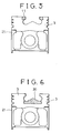
- Figs. 5 to 7 each show an embodiment in which a metal-ceramic insert composite of the present invention is applied to a two-piece piston of a direct injection diesel engine, ceramics being used only for parts where the heat load is large.
- a lip portion 11 provided at the opening of a piston combustion chamber is formed using silicon nitride having excellent heat resistance, the outer side of the lip portion comprises a low-expansion cast ferrous alloy member 3.
- the numeral 21 indicates a skirt portion made of aluminum.
- Fig. 6 shows an embodiment in which silicon nitride having excellent heat resistance and thermal insulation is used for a relatively large part 20 ⁇ which occupies the whole bottom portion including the center of the piston combustion chamber.
- silicon nitride having excellent heat resistance and thermal insulation is used for a relatively large part 20 ⁇ which occupies the whole bottom portion including the center of the piston combustion chamber.
- Fig. 7 shows an embodiment combining the embodiment of Fig. 5 with that of Fig. 6, where the measures against heat load are more effective and heat insulation of the combustion chamber is larger than the embodiment in Fig. 5 or 6. It has been impossible by conventional methods such as shrink fitting to provide a combustion chamber comprising plural ceramic members like the embodiment shown in Fig. 7. However, the present invention makes it possible to use ceramics separately, destruction of the ceramic members being prevented.
- Fig. 8 shows an embodiment which employs a metal-ceramic insert composite of the present invention.
- the inner side of the exhaust port 14 provided in the cylinder head body 13 of a diesel engine was made of a tubular aluminum titanate member, and a valve guide 15 was made of a silicon nitride member.
- a value sheet 16 was made of silicon nitride
- a cylinder head plate 17 serving as a fire-contact surface was made of a silicon nitride disc-shaped member.
- This structure was designed for decreasing heat loss of the exhaust port, abrasion of the valve guide 15 and valve sheet 16, and heat loss of the fire-contact surface.
- the body 13 is insert case of a low-expansion cast ferrous alloy described for other embodiments.
- the metal-ceramic insert composite of the present invention causes small stress in a ceramic at the room temperature and can be produced by a simple process at a low cost because machining of the bond portion between the ceramic and metal is not required.
- the metal-ceramic composite obtained has sufficient bonding strength between the ceramic and metal even at high temperatures.
- the present invention provides a metal-ceramic composite structure which facilitates the use of ceramics having low reliability due to their brittleness as mechanical structural members. Since the invention thus enables the practical use of mechanical structural members which are formed by employing the characteristics of ceramics such as the heat resistance, abrasion resistance, light weight and thermal insulation, this invention is very useful in the industrial feild.
Landscapes
- Engineering & Computer Science (AREA)
- Mechanical Engineering (AREA)
- Chemical & Material Sciences (AREA)
- Combustion & Propulsion (AREA)
- General Engineering & Computer Science (AREA)
- Materials Engineering (AREA)
- Metallurgy (AREA)
- Organic Chemistry (AREA)
- Ceramic Engineering (AREA)
- Ceramic Products (AREA)
Claims (9)
- Composite en céramique et métal comprenant un corps en céramique (1, 6, 11, 14, 18, 20) et un alliage ferreux coulé, à faible dilatation (3, 13) fixé sur celui-ci par coulage par insert,
caractérisé en ce que ledit alliage ferreux coulé, à faible dilatation, a une composition consistant essentiellement en poids en 0,3 à 2,0% de C, 25 à 32% de Ni, 12 à 20% de Co, 0,3 à 2,0% de Si, 0,2 à 0,8% de Nb, 0,01 à 0,2% de Mg ou Ca, 1,0% ou moins de Mn, le restant en Fe et impuretés inévitables et ayant un coefficient de dilatation thermique dans l'intervalle de 3,5 x 10⁻⁶/°C à 5,5 x 10⁻⁶/°C de la température ambiante à 400°C. - Composite en céramique et métal selon la revendication 1, comprenant de plus un alliage d'aluminium (12) fixé par coulage par insert audit alliage ferreux à faible dilatation.
- Composite en céramique et métal selon la revendication 1 ou la revendication 2 dans lequel l'épaisseur moyenne dudit corps en céramique est plus grande que l'épaisseur moyenne dudit alliage ferreux coulé.
- Composite en céramique et métal selon l'une quelconque des revendications 1 à 3 qui est un piston.
- Composite en céramique et métal selon la revendication 4, dans lequel le corps en céramique fournit au moins l'un d'une portion de lèvre à l'ouverture d'une chambre de combustion et du centre de la chambre à combustion.
- Méthode de production d'un insert composite en céramique et métal comprenant un insert en céramique (1, 6, 11, 15, 16, 18, 20) fixé à un alliage ferreux coulé, à faible dilatation (3) par coulage par insert, comprenant les étapes d'arranger l'insert en céramique (1, 6, 11, 15, 16, 18, 20) dans un moule (2) et de couler l'alliage ferreux, à faible dilatation, fondu (3) autour de l'insert en céramique, caractérisée en ce que ledit alliage ferreux coulé, à faible dilatation, a une composition consistant essentiellement en poids en 0,3 à 2,0% de C, 25 à 32% de Ni, 12 à 20% de Co, 0,3 à 2,0% de Si, 0,2 à 0,8% de Nb, 0,01 à 0,2% de Mg ou de Ca, 1,0% ou moins de Mn, le restant en Fe et impuretés inévitables et ayant un coefficient de dilatation thermique dans l'intervalle de 3,5 x 10⁻⁶/°C à 5,5 x 10⁻⁶/°C de la température ambiante à 400°C.
- Méthode selon la revendication 6 dans laquelle une pression est appliquée audit alliage ferreux après qu'il a été coulé dans le moule en évacuant le moule (2) et/ou en appliquant une pression à l'alliage.
- Méthode selon la revendication 6 ou la revendication 7 comprenant l'étape supplémentaire de joindre un insert d'alliage d'aluminium (12, 21) à l'alliage ferreux coulé à faible dilatation (3).
- Méthode selon la revendication 8 dans laquelle le coefficient de dilatation thermique de l'alliage ferreux coulé, à faible dilatation (3) est supérieur à celui de l'insert en céramique (1, 6, 11, 15, 16, 18, 20).
Applications Claiming Priority (2)
| Application Number | Priority Date | Filing Date | Title |
|---|---|---|---|
| JP19445390 | 1990-07-23 | ||
| JP194453/90 | 1990-07-23 |
Publications (2)
| Publication Number | Publication Date |
|---|---|
| EP0468722A1 EP0468722A1 (fr) | 1992-01-29 |
| EP0468722B1 true EP0468722B1 (fr) | 1995-08-23 |
Family
ID=16324821
Family Applications (1)
| Application Number | Title | Priority Date | Filing Date |
|---|---|---|---|
| EP91306653A Expired - Lifetime EP0468722B1 (fr) | 1990-07-23 | 1991-07-22 | Insert en céramique et métal |
Country Status (2)
| Country | Link |
|---|---|
| EP (1) | EP0468722B1 (fr) |
| DE (1) | DE69112314T2 (fr) |
Families Citing this family (3)
| Publication number | Priority date | Publication date | Assignee | Title |
|---|---|---|---|---|
| JP3381845B2 (ja) * | 1999-07-08 | 2003-03-04 | 日立金属株式会社 | 被削性に優れた低熱膨張鋳鋼 |
| DE102007061601A1 (de) * | 2007-12-20 | 2009-06-25 | Mahle International Gmbh | Kolben für einen Verbrennungsmotor sowie Verfahren zu seiner Herstellung |
| DE102016108900B4 (de) * | 2016-05-13 | 2019-05-16 | Phitea GmbH | Kolben für eine Hubkolbenbrennkraftmaschine und Verfahren zum Herstellen eines solchen |
Family Cites Families (2)
| Publication number | Priority date | Publication date | Assignee | Title |
|---|---|---|---|---|
| JPS62107216A (ja) * | 1985-11-05 | 1987-05-18 | Ngk Insulators Ltd | バルブシートインサート及びその製造法並びにそれを使用してなるシリンダーヘッド |
| JPS62182174A (ja) * | 1986-02-05 | 1987-08-10 | 日本碍子株式会社 | セラミツクス・金属複合体 |
-
1991
- 1991-07-22 EP EP91306653A patent/EP0468722B1/fr not_active Expired - Lifetime
- 1991-07-22 DE DE69112314T patent/DE69112314T2/de not_active Expired - Fee Related
Non-Patent Citations (3)
| Title |
|---|
| Metals Handbook, Ninth Edition, 1980, Vol 3, "Low expansion alloys", Fig 3. page 7 * |
| WORLD PATENT INDEX, FILE SUPPLIER, Abstract AN=88-253280, Derwent Publications Ltd., London, GB & JP-A-63183151 (TOSHIBA KK) * |
| WORLD PATENT INDEX, FILE SUPPLIER, Abstract AN=89-110102, Derwent Publications Ltd., London, GB & JP-A-1055364 (NIPPON CHUZO KK) 2-3-89 * |
Also Published As
| Publication number | Publication date |
|---|---|
| DE69112314D1 (de) | 1995-09-28 |
| DE69112314T2 (de) | 1996-04-18 |
| EP0468722A1 (fr) | 1992-01-29 |
Similar Documents
| Publication | Publication Date | Title |
|---|---|---|
| US5137789A (en) | Composite ceramic and metal article | |
| JP2866064B2 (ja) | 内燃機関用鋳造金属ピストン | |
| US4830932A (en) | Heat resistant light alloy articles and method of manufacturing same | |
| CA1157486A (fr) | Pieces pour moteurs thermiques | |
| EP0530854B1 (fr) | Liaison de corps en métal et céramique | |
| JPH0250173B2 (fr) | ||
| EP0710729B1 (fr) | Pistons métalliques à renforcement fibreux | |
| US4709621A (en) | Internal combustion engine piston and a method of producing the same | |
| JPS60190651A (ja) | エンジン用ピストンおよびその製造法 | |
| US5511521A (en) | Light-alloy piston with a combustion bowl | |
| US5144885A (en) | Ceramic-metal friction welding member and ceramic cast-in bonded piston made thereof | |
| EP0468722B1 (fr) | Insert en céramique et métal | |
| JP2920004B2 (ja) | セラミックスと金属の鋳ぐるみ複合体 | |
| US4651630A (en) | Thermally insulating pistons for internal combustion engines and method for the manufacture thereof | |
| JP2591872B2 (ja) | 窒化珪素鋳ぐるみピストン | |
| JPH028894B2 (fr) | ||
| JPH02104950A (ja) | 内燃機関のピストン | |
| EP0447701B1 (fr) | Elément résistant à la chaleur renforcée et son procédé de préparation | |
| JP2002283029A (ja) | ダイカスト用スリーブ | |
| US5013610A (en) | Heat resisting member reinforced locally by an inorganic fiber and a productive method of the same | |
| EP0191008A1 (fr) | Carapace ou objet tubulaire et leur procédé de fabrication | |
| JPH06272614A (ja) | 内燃機関のシリンダライナ | |
| JPH02115555A (ja) | セラミックスー金属の摩擦圧接体およびそれから成るセラミックス鋳ぐるみピストン | |
| JPS60166156A (ja) | セラミツクス−金属系複合体の製造方法 | |
| JP2868164B2 (ja) | セラミック鋳ぐるみピストン及びその製造方法 |
Legal Events
| Date | Code | Title | Description |
|---|---|---|---|
| PUAI | Public reference made under article 153(3) epc to a published international application that has entered the european phase |
Free format text: ORIGINAL CODE: 0009012 |
|
| AK | Designated contracting states |
Kind code of ref document: A1 Designated state(s): DE FR GB IT SE |
|
| 17P | Request for examination filed |
Effective date: 19920610 |
|
| 17Q | First examination report despatched |
Effective date: 19930721 |
|
| GRAA | (expected) grant |
Free format text: ORIGINAL CODE: 0009210 |
|
| AK | Designated contracting states |
Kind code of ref document: B1 Designated state(s): DE FR GB IT SE |
|
| REF | Corresponds to: |
Ref document number: 69112314 Country of ref document: DE Date of ref document: 19950928 |
|
| ITF | It: translation for a ep patent filed | ||
| ET | Fr: translation filed | ||
| PLBE | No opposition filed within time limit |
Free format text: ORIGINAL CODE: 0009261 |
|
| STAA | Information on the status of an ep patent application or granted ep patent |
Free format text: STATUS: NO OPPOSITION FILED WITHIN TIME LIMIT |
|
| 26N | No opposition filed | ||
| PGFP | Annual fee paid to national office [announced via postgrant information from national office to epo] |
Ref country code: GB Payment date: 20010712 Year of fee payment: 11 |
|
| PGFP | Annual fee paid to national office [announced via postgrant information from national office to epo] |
Ref country code: FR Payment date: 20010717 Year of fee payment: 11 |
|
| PGFP | Annual fee paid to national office [announced via postgrant information from national office to epo] |
Ref country code: DE Payment date: 20010721 Year of fee payment: 11 |
|
| PGFP | Annual fee paid to national office [announced via postgrant information from national office to epo] |
Ref country code: SE Payment date: 20010723 Year of fee payment: 11 |
|
| REG | Reference to a national code |
Ref country code: GB Ref legal event code: IF02 |
|
| PG25 | Lapsed in a contracting state [announced via postgrant information from national office to epo] |
Ref country code: GB Free format text: LAPSE BECAUSE OF NON-PAYMENT OF DUE FEES Effective date: 20020722 |
|
| PG25 | Lapsed in a contracting state [announced via postgrant information from national office to epo] |
Ref country code: SE Free format text: LAPSE BECAUSE OF NON-PAYMENT OF DUE FEES Effective date: 20020723 |
|
| PG25 | Lapsed in a contracting state [announced via postgrant information from national office to epo] |
Ref country code: DE Free format text: LAPSE BECAUSE OF NON-PAYMENT OF DUE FEES Effective date: 20030201 |
|
| EUG | Se: european patent has lapsed | ||
| GBPC | Gb: european patent ceased through non-payment of renewal fee |
Effective date: 20020722 |
|
| PG25 | Lapsed in a contracting state [announced via postgrant information from national office to epo] |
Ref country code: FR Free format text: LAPSE BECAUSE OF NON-PAYMENT OF DUE FEES Effective date: 20030331 |
|
| REG | Reference to a national code |
Ref country code: FR Ref legal event code: ST |
|
| PG25 | Lapsed in a contracting state [announced via postgrant information from national office to epo] |
Ref country code: IT Free format text: LAPSE BECAUSE OF NON-PAYMENT OF DUE FEES Effective date: 20050722 |