EP0468738A2 - Process and belt forming drum for assembling a green tyre - Google Patents
Process and belt forming drum for assembling a green tyre Download PDFInfo
- Publication number
- EP0468738A2 EP0468738A2 EP91306681A EP91306681A EP0468738A2 EP 0468738 A2 EP0468738 A2 EP 0468738A2 EP 91306681 A EP91306681 A EP 91306681A EP 91306681 A EP91306681 A EP 91306681A EP 0468738 A2 EP0468738 A2 EP 0468738A2
- Authority
- EP
- European Patent Office
- Prior art keywords
- breaker
- belt
- drum
- tyre
- carcass
- Prior art date
- Legal status (The legal status is an assumption and is not a legal conclusion. Google has not performed a legal analysis and makes no representation as to the accuracy of the status listed.)
- Withdrawn
Links
Images



Classifications
-
- B—PERFORMING OPERATIONS; TRANSPORTING
- B29—WORKING OF PLASTICS; WORKING OF SUBSTANCES IN A PLASTIC STATE IN GENERAL
- B29D—PRODUCING PARTICULAR ARTICLES FROM PLASTICS OR FROM SUBSTANCES IN A PLASTIC STATE
- B29D30/00—Producing pneumatic or solid tyres or parts thereof
- B29D30/06—Pneumatic tyres or parts thereof (e.g. produced by casting, moulding, compression moulding, injection moulding, centrifugal casting)
- B29D30/08—Building tyres
-
- B—PERFORMING OPERATIONS; TRANSPORTING
- B29—WORKING OF PLASTICS; WORKING OF SUBSTANCES IN A PLASTIC STATE IN GENERAL
- B29D—PRODUCING PARTICULAR ARTICLES FROM PLASTICS OR FROM SUBSTANCES IN A PLASTIC STATE
- B29D30/00—Producing pneumatic or solid tyres or parts thereof
- B29D30/06—Pneumatic tyres or parts thereof (e.g. produced by casting, moulding, compression moulding, injection moulding, centrifugal casting)
- B29D30/08—Building tyres
- B29D30/20—Building tyres by the flat-tyre method, i.e. building on cylindrical drums
- B29D30/24—Drums
- B29D30/244—Drums for manufacturing substantially cylindrical tyre components with cores or beads, e.g. carcasses
- B29D30/245—Drums for the single stage building process, i.e. the building-up of the cylindrical carcass and the toroidal expansion of it are realised on the same drum
Definitions
- the present invention relates to a process for assembling green tyres and a belt forming drum for practising the process.
- Figure 7 shows a tyre T for motor vehicles which is generally known and which comprises a carcass 1 having beads 2 within the respective opposed ends along its inner periphery, a tread 4 provided over the outer periphery of the carcass 1 with a breaker 3 interposed therebetween, sidewalls 5 provided on opposite side faces of the carcass 1, and a breaker cushion 6 embedded between the carcass 1 and each edge portion of the breaker 3.
- a breaker 3 which is in the form of a hollow cylinder is adhered to the toroidal carcass 1 to form a green tyre, a space or clearance occurs towards the edges of the breaker and the breaker cushions 6 are positioned on the carcass 1 to fill the space so the breaker 3 may have the desired cylindrical form.
- FIG 8 shows an example of an apparatus for building such a green tyre.
- the apparatus comprises headstocks 8,9 mounted on the respective ends of a base 7 and having a common horizontal axis, a belt drum 12 and a tyre carcass building drum 13 which are both radially expandable and contractible and which are rotatably supported, each at one end, respectively by rotary shafts 10,11 on the headstocks 8,9.
- Belt transport means 14 are provided which can be moved between the two drums 12,13.
- the tyre carcass building drum 13 comprises a drum body composed of a plurality of drum segments divided circumferentially thereof, an annular inflatable shaping bladder 15 around the drum body, and inflatable side bladders 16 arranged on respective axially opposite sides of the forming bladder 15.
- the belt drum 12 is in the form of a hollow cylinder comprising a plurality of drum segments divided circumferentially thereof and radially expandable and contractible.
- a belt B comprising a breaker 3 and a tread 4 is formed using the apparatus shown in Figure 8 as now follows.
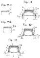
- the breaker is wound on one or a plurality of layers around the belt drum 12 in its radially expanded condition (Figure 9,I).
- the tread 4 is wound around and adhered to the breaker 3 ( Figure 9,II) to form the belt B in the shape of a hollow cylinder.
- the drum 12 is then radially contracted, and the belt B is taken from the drum by means of the belt transport means 14, which is then placed in a stand-by position.
- the tyre carcass building drum 13 is radially contracted and then a tyre carcass component material 1a is wound around the shaping bladder 15 and the side bladders 16 to form a cylindrical tube.
- a pair of beads 2 and a pair of breaker cushions 6 are fitted one to the tube in the positions shown in Figure 10(I).
- the belt building drum 12 is slightly expanded to engage and lock the beads 2.
- the side bladders 16 are then inflated to fold the carcass material 1a around the beads 2, and the shaping bladder 15 is thereafter inflated to shape the carcass 1 into a toroidal shape as seen in Figure 10 (III).
- the waiting transport means 14 is moved to position the belt B around the outer periphery of the carcass 1 as shown in Figure 11, the shaping bladder is then slightly inflated to fixedly position the belt B on the carcass 1 in the required position, and the transport means 14 is retracted.
- the forming bladder 15 is thereafter further inflated to intimately fit together the carcass 1, the breaker 3 and the breaker cushions 6 as seen in Figure 12.
- sidewalls 5 are adhered to the respective side faces of the carcass 1, and the shaping bladder 15 and the building drum 13 are contracted to allow removal of the completed green tyre from the apparatus.
- the green tyre thus formed is subjected to heat and pressure in a vulcanising press to bond the components together and mould the completed tyre with its tread pattern.
- the breaker cushions 6 are affixed to the carcass 1 in the form of a hollow cylinder, which is thereafter radially expanded to the final toroidal shape. This makes extreme difficulties in forming the breaker cushions 6 of the required configuration in the finished tyre. Also it is impossible to position the breaker 3 in the tyre structure with its desired cylindrical shape with any real degree of accuracy. These difficulties lead to variations in the tyre which have an adverse effect on tyre uniformity and impair durability in service.
- An object of the present invention is to provide a green tyre building process and a belt drum which position the breaker with high accuracy.
- the present invention provides a green tyre building process wherein a cylindrical belt comprises a tread and a breaker and sidewalls are applied around a toroidally shaped tyre carcass on a tyre carcass building drum to assemble a green tyre characterised by fitting breaker cushions to the inner circumferential surfaces of the opposite edge portions of the breaker prior to applying the belt around the tyre carcass.
- each of the breaker cushions is wound around the belt forming drum so as to make the inner peripheral surface of the cushion curved or tapered to suit the toroidal shape it has in the completed tyre and to make the outer periphery thereof substantially straight-surfaced so that the breaker may be fitted to the cushions with its correct shape.
- the breaker cushions are initially made and retain a diameter substantially that of the final product and are not radially enlarged or deformed unlike those of the prior art.
- the result is that the breaker can be positioned in the tyre structure axially of the tyre in a cylindrical form with high accuracy. This ensure good tyre uniformity and gives improved durability to the tyre.
- the present invention provides a green tyr ebuilding process wherein a cylindrical belt comprising a tread and a breaker and sidewalls are applied around a toroidally shaped tyre carcass on a tyre band building drum to build a green tyre characterised in that breaker cushions are fitted to the inner circumferential surfaces of the opposite end positions of the breaker prior to applying the belt around the tyre carcass.
- the present invention further provides a belt building drum which is characterised in that the drum is formed at each of its axially opposite ends with a portion for winding a breaker cushions therearound, and this portion is so shaped as to have a diameter decreasing toward the axially outer extremity thereof.
- the portion of decreasing diameter has in cross section a tapered surface or profile. It may alternatively be of curved cross sectional profile.
- the belt drum of the invention is so shaped that the axially opposite end portions of its outer periphery have a diameter decreasing towards the outer extremities. Accordingly, the breaker cushions can be affixed to the respective end portions of inner periphery of the breaker readily, properly and accurately. This permits the breaker to retain its shaped and axial position to result in improved formability.
- FIG. 1 shows a belt drum 12 comprising segments 12a each having at its opposite ends an outer surface slanting radially inwardly of the drum.
- the drum 12 is formed at each of its axially opposite ends with an outer peripheral tapered surface 17 having a diameter decreasing toward its outer edges.
- Each tapered surface 17 provides a breaker cushions supporting surface and the assembly is such that when the drum 12 is radially expanded, the outer periphery of the mid-portion of the drum 12 is level with the outer peripheral surface 6a of the breaker cushion 6 fitted around the tapered surface 17.
- the breaker cushion 6 can be accurately positioned by placing it on its respective tapered surface 17.
- a belt B can be formed in which the breaker cushions 6 are affixed to the respective opposite edge portions of the inner periphery of the breaker 3.
- the belt B is formed by the procedure to be described below with reference to Figure 2 (I) to (IV).
- a breaker cushion 6, which is prepared in advance by extrusion in the form of a ring of triangular cross section, is positioned around each tapered surface 17 of the belt forming drum 12 which is radially contracted.
- the drum 12 is then radially expanded to engage both cushions 6 on the tapered surface 17.
- a breaker 3 is wound around and affixed to the drum 12 as shown in Figure 2,(II) so that it is over both cushions 6.
- a tread 4 is wound around and affixed to the outer periphery of the breaker 3 to complete the subb-assembly of the belt B.
- the belt transport means 14 takes hold of the belt B, the belt drum 12 is contracted, and the transport means 14 is moved towards the tyre carcass building drum 13 to a stand-by position where it meets the holding belt B.
- a liner and carcass ply sheet materials 1a is wrapped around and affixed to the drum 13 in its radially contracted condition to form a hollow cylindrical tube, and a pair of preassembled beads 2 already fitted with apexes is fitted over the tube each positioned as seen in Figure 3,(I).
- the drum 13 is slightly increased in diameter to lock in place the beads 2 and the side bladders 16 are inflated to fold the liner and ply material 1a around the beads as shown in Figure 3,(II).
- the forming bladder 15 is thereafter inflated as seen in Figure 3,(III), whereby the carcass 1 is formed into a toroidal shape.
- the belt transport means 14 is then moved from the stand-by position to place the belt B around the carcass 1 as shown in Figure 4 with an accurately set relative axial arrangement.
- the shaping bladder 15 is slightly inflated to engage the belt B in position on the carcass 1, the transport means 14 is retracted towards the belt forming drum 12, and the forming bladder 15 is further inflated to bring the carcass 1 into full intimate contact with the breaker 3 and the breaker cushions 6 as shown in Figure 5.
- a sidewall 5 is fitted to each opposite side face of the carcass 1 as shown in Figure 6, the shaping bladder 15 is contracted, the drum 13 is radially contracted, and the resulting green tyre assembly is removed from the drum 13.
- the green tyre thus formed is later cured in a mould under heat and pressured to bond and cure the components and complete a tyre having a tread pattern.
- the tread 4 can alternatively be fitted over the outer side of the sidewall 5 as shown in the left half of Figure 7.
- the sidewall 5 is affixed to each of the opposite side faces of the carcass 1 as formed in the toroidal shape, and the belt B is thereafter fitted around and affixed to the carcass 1.
- the invention can be applied to either sidewall over tread or tread over sidewall tyre construction.
- the invention provides an effective method of assembling a tyre and a particular belt drum for said method which allows the breaker to have a predetermined substantially flat shape and provides for cushions to be used at the belt edges.
- the method and apparatus allow great precision in component assembly, substantially eliminates changes of diameter and cross section of the cushions and provides tyres of improved accuracy, uni formity and structural integrity.
Landscapes
- Engineering & Computer Science (AREA)
- Mechanical Engineering (AREA)
- Manufacturing & Machinery (AREA)
- Tyre Moulding (AREA)
Abstract
Description
- The present invention relates to a process for assembling green tyres and a belt forming drum for practising the process.
- Figure 7 shows a tyre T for motor vehicles which is generally known and which comprises a
carcass 1 havingbeads 2 within the respective opposed ends along its inner periphery, atread 4 provided over the outer periphery of thecarcass 1 with abreaker 3 interposed therebetween,sidewalls 5 provided on opposite side faces of thecarcass 1, and abreaker cushion 6 embedded between thecarcass 1 and each edge portion of thebreaker 3. When thebreaker 3 which is in the form of a hollow cylinder is adhered to thetoroidal carcass 1 to form a green tyre, a space or clearance occurs towards the edges of the breaker and thebreaker cushions 6 are positioned on thecarcass 1 to fill the space so thebreaker 3 may have the desired cylindrical form. - Figure 8 shows an example of an apparatus for building such a green tyre. The apparatus comprises
headstocks base 7 and having a common horizontal axis, abelt drum 12 and a tyrecarcass building drum 13 which are both radially expandable and contractible and which are rotatably supported, each at one end, respectively byrotary shafts 10,11 on theheadstocks drums carcass building drum 13 comprises a drum body composed of a plurality of drum segments divided circumferentially thereof, an annularinflatable shaping bladder 15 around the drum body, andinflatable side bladders 16 arranged on respective axially opposite sides of the formingbladder 15. Thebelt drum 12 is in the form of a hollow cylinder comprising a plurality of drum segments divided circumferentially thereof and radially expandable and contractible. - The process illustrated in Figures 9 to 13 is already known as a process for building green tyres. With reference to Figure 9, a belt B comprising a
breaker 3 and atread 4 is formed using the apparatus shown in Figure 8 as now follows. The breaker is wound on one or a plurality of layers around thebelt drum 12 in its radially expanded condition (Figure 9,I). Thetread 4 is wound around and adhered to the breaker 3 (Figure 9,II) to form the belt B in the shape of a hollow cylinder. Thedrum 12 is then radially contracted, and the belt B is taken from the drum by means of the belt transport means 14, which is then placed in a stand-by position. - The tyre
carcass building drum 13 is radially contracted and then a tyrecarcass component material 1a is wound around theshaping bladder 15 and theside bladders 16 to form a cylindrical tube. A pair ofbeads 2 and a pair ofbreaker cushions 6 are fitted one to the tube in the positions shown in Figure 10(I). Next, as shown in Figure 10 (II), thebelt building drum 12 is slightly expanded to engage and lock thebeads 2. Theside bladders 16 are then inflated to fold thecarcass material 1a around thebeads 2, and theshaping bladder 15 is thereafter inflated to shape thecarcass 1 into a toroidal shape as seen in Figure 10 (III). - Subsequently, the waiting transport means 14 is moved to position the belt B around the outer periphery of the
carcass 1 as shown in Figure 11, the shaping bladder is then slightly inflated to fixedly position the belt B on thecarcass 1 in the required position, and the transport means 14 is retracted. The formingbladder 15 is thereafter further inflated to intimately fit together thecarcass 1, thebreaker 3 and thebreaker cushions 6 as seen in Figure 12. As seen in Figure 13,sidewalls 5 are adhered to the respective side faces of thecarcass 1, and theshaping bladder 15 and thebuilding drum 13 are contracted to allow removal of the completed green tyre from the apparatus. The green tyre thus formed is subjected to heat and pressure in a vulcanising press to bond the components together and mould the completed tyre with its tread pattern. - With the conventional green tyre assembly process described, the
breaker cushions 6 are affixed to thecarcass 1 in the form of a hollow cylinder, which is thereafter radially expanded to the final toroidal shape. This makes extreme difficulties in forming thebreaker cushions 6 of the required configuration in the finished tyre. Also it is impossible to position thebreaker 3 in the tyre structure with its desired cylindrical shape with any real degree of accuracy. These difficulties lead to variations in the tyre which have an adverse effect on tyre uniformity and impair durability in service. - An object of the present invention is to provide a green tyre building process and a belt drum which position the breaker with high accuracy.
- Accordingly the present invention provides a green tyre building process wherein a cylindrical belt comprises a tread and a breaker and sidewalls are applied around a toroidally shaped tyre carcass on a tyre carcass building drum to assemble a green tyre characterised by fitting breaker cushions to the inner circumferential surfaces of the opposite edge portions of the breaker prior to applying the belt around the tyre carcass.
- In the step of winding the breaker cushions, each of the breaker cushions is wound around the belt forming drum so as to make the inner peripheral surface of the cushion curved or tapered to suit the toroidal shape it has in the completed tyre and to make the outer periphery thereof substantially straight-surfaced so that the breaker may be fitted to the cushions with its correct shape.
- By means of the present invention, the breaker cushions are initially made and retain a diameter substantially that of the final product and are not radially enlarged or deformed unlike those of the prior art. The result is that the breaker can be positioned in the tyre structure axially of the tyre in a cylindrical form with high accuracy. This ensure good tyre uniformity and gives improved durability to the tyre.
- Specifically the present invention provides a green tyr ebuilding process wherein a cylindrical belt comprising a tread and a breaker and sidewalls are applied around a toroidally shaped tyre carcass on a tyre band building drum to build a green tyre characterised in that breaker cushions are fitted to the inner circumferential surfaces of the opposite end positions of the breaker prior to applying the belt around the tyre carcass.
- The present invention further provides a belt building drum which is characterised in that the drum is formed at each of its axially opposite ends with a portion for winding a breaker cushions therearound, and this portion is so shaped as to have a diameter decreasing toward the axially outer extremity thereof.
- In one arrangement the portion of decreasing diameter has in cross section a tapered surface or profile. It may alternatively be of curved cross sectional profile.
- Thus, the belt drum of the invention is so shaped that the axially opposite end portions of its outer periphery have a diameter decreasing towards the outer extremities. Accordingly, the breaker cushions can be affixed to the respective end portions of inner periphery of the breaker readily, properly and accurately. This permits the breaker to retain its shaped and axial position to result in improved formability.
- An embodiment of the present invention will now be described by way of example only, in conjunction with the attached diagrammatic drawings in which:
- Figure 1 is a front view partially broken away showing a belt forming drum;
- Figure 2, (I) to (IV) also illustrate a belt forming step;
- Figure 3, (I) to (III) show a carcass forming step;
- Figure 4 shows a carcass and a belt;
- Figure 5 shows the belt as fitted around the carcass in intimate contact therewith;
- Figure 6 shows sidewalls affixed to the carcass;
- Figure 7 is a sectional view of a tyre;
- Figure 8 to Figure 13 show a conventional prior art example;
- Figure 8 is a front view schematically showing a green tyre forming apparatus;
- Figure 9 (I) to (II) illustrate a belt forming step;
- Figure 10 (I) to (III) illustrate a carcass forming step;
- Figure 11 illustrates a belt as fitted around a carcass;
- Figure 12 illustrates the belt fitted to the carcass; and
- Figure 13 shows sidewalls affixed to the carcass.
- Since the structure of the tyre and the basic construction of the forming apparatus are the same as those of the prior art shown in Figure 7 to Figure 13, like parts are designated by like reference numerals.
- Figure 1 shows a
belt drum 12 comprisingsegments 12a each having at its opposite ends an outer surface slanting radially inwardly of the drum. Thus, thedrum 12 is formed at each of its axially opposite ends with an outer peripheraltapered surface 17 having a diameter decreasing toward its outer edges. Eachtapered surface 17 provides a breaker cushions supporting surface and the assembly is such that when thedrum 12 is radially expanded, the outer periphery of the mid-portion of thedrum 12 is level with the outer peripheral surface 6a of thebreaker cushion 6 fitted around thetapered surface 17. Thus, thebreaker cushion 6 can be accurately positioned by placing it on its respectivetapered surface 17. Thus by using thebelt forming drum 12 of the invention a belt B can be formed in which thebreaker cushions 6 are affixed to the respective opposite edge portions of the inner periphery of thebreaker 3. - The belt B is formed by the procedure to be described below with reference to Figure 2 (I) to (IV). First, as shown in Figure 2 (I), a
breaker cushion 6, which is prepared in advance by extrusion in the form of a ring of triangular cross section, is positioned around eachtapered surface 17 of thebelt forming drum 12 which is radially contracted. Thedrum 12 is then radially expanded to engage bothcushions 6 on thetapered surface 17. Next abreaker 3 is wound around and affixed to thedrum 12 as shown in Figure 2,(II) so that it is over bothcushions 6. Then as shown in Figure 2,(III), atread 4 is wound around and affixed to the outer periphery of thebreaker 3 to complete the subb-assembly of the belt B. Subsequently, the belt transport means 14 takes hold of the belt B, thebelt drum 12 is contracted, and thetransport means 14 is moved towards the tyrecarcass building drum 13 to a stand-by position where it meets the holding belt B. - To build a
carcass 1, on the other hand, a liner and carcassply sheet materials 1a is wrapped around and affixed to thedrum 13 in its radially contracted condition to form a hollow cylindrical tube, and a pair of preassembledbeads 2 already fitted with apexes is fitted over the tube each positioned as seen in Figure 3,(I). Thedrum 13 is slightly increased in diameter to lock in place thebeads 2 and theside bladders 16 are inflated to fold the liner and plymaterial 1a around the beads as shown in Figure 3,(II). The formingbladder 15 is thereafter inflated as seen in Figure 3,(III), whereby thecarcass 1 is formed into a toroidal shape. - The belt transport means 14 is then moved from the stand-by position to place the belt B around the
carcass 1 as shown in Figure 4 with an accurately set relative axial arrangement. The shapingbladder 15 is slightly inflated to engage the belt B in position on thecarcass 1, the transport means 14 is retracted towards thebelt forming drum 12, and the formingbladder 15 is further inflated to bring thecarcass 1 into full intimate contact with thebreaker 3 and the breaker cushions 6 as shown in Figure 5. Asidewall 5 is fitted to each opposite side face of thecarcass 1 as shown in Figure 6, the shapingbladder 15 is contracted, thedrum 13 is radially contracted, and the resulting green tyre assembly is removed from thedrum 13. - The green tyre thus formed is later cured in a mould under heat and pressured to bond and cure the components and complete a tyre having a tread pattern.
- Although the
sidewalls 5 are fitted over the outer side of thetread 4 according to the above embodiment as shown in the right half of Figure 7, thetread 4 can alternatively be fitted over the outer side of thesidewall 5 as shown in the left half of Figure 7. In this case, thesidewall 5 is affixed to each of the opposite side faces of thecarcass 1 as formed in the toroidal shape, and the belt B is thereafter fitted around and affixed to thecarcass 1. Thus the invention can be applied to either sidewall over tread or tread over sidewall tyre construction. - The invention provides an effective method of assembling a tyre and a particular belt drum for said method which allows the breaker to have a predetermined substantially flat shape and provides for cushions to be used at the belt edges. The method and apparatus allow great precision in component assembly, substantially eliminates changes of diameter and cross section of the cushions and provides tyres of improved accuracy, uni formity and structural integrity.
Claims (6)
- A green tyre building process wherein a cylindrical belt (B) comprising a tread (A) and a breaker (3) and sidewalls (5) are applied around a toroidally shaped tyre carcass (1) on a tyre carcass building drum (13) to assemble a green tyre characterised by fitting breaker cushions (6) to the inner circumferential surfaces of the opposite edge portions of the breaker (3) prior to applying the belt (B) around the tyre carcass (1).
- A process according to Claim 1 characterised by assembling the belt B in the form of a hollow cylinder by fitting breaker cushions 6 around the respective axially opposite end portions of a belt forming drum 12, wrapping a breaker 3 around the belt forming drum 12 over the breaker cushions 6 and thereafter winding a tread 4 around the breaker 3 removing the cylindrical belt B from the belt forming drum 12.
- The process as defined in claim 2 characterised in that in the step of fitting the breaker cushions 6, each of the breaker cushions 6 is wound around the belt forming drum 12 so as to make the inner peripheral surface of the cushion curved or tapered to allow conformity of the toroidal shape of the carcass to be fitted and to make the outer periphery of the cushion 6 straight-surfaced.
- A belt forming drum characterised in that the belt forming drum 12 is formed at each of its axially opposite ends with a tapered portion (17) for winding a breaker cushion therearound, each said portion (17) being so shaped as to have a diameter decreasing towards the axially outer extremity thereof.
- A drum as defined in claim 4 characterised in that said portion (17) of decreasing diameter has in cross section a tapered surface or profile.
- A drum as defined in claim 4 characterised in that said portion (17) of decreasing diameter has in cross section a curved surface of profile.
Applications Claiming Priority (2)
| Application Number | Priority Date | Filing Date | Title |
|---|---|---|---|
| JP197385/90 | 1990-07-25 | ||
| JP2197385A JPH089204B2 (en) | 1990-07-25 | 1990-07-25 | Raw tire forming method and belt forming drum |
Publications (2)
| Publication Number | Publication Date |
|---|---|
| EP0468738A2 true EP0468738A2 (en) | 1992-01-29 |
| EP0468738A3 EP0468738A3 (en) | 1992-05-27 |
Family
ID=16373633
Family Applications (1)
| Application Number | Title | Priority Date | Filing Date |
|---|---|---|---|
| EP19910306681 Withdrawn EP0468738A3 (en) | 1990-07-25 | 1991-07-23 | Process and belt forming drum for assembling a green tyre |
Country Status (3)
| Country | Link |
|---|---|
| US (1) | US5248357A (en) |
| EP (1) | EP0468738A3 (en) |
| JP (1) | JPH089204B2 (en) |
Cited By (3)
| Publication number | Priority date | Publication date | Assignee | Title |
|---|---|---|---|---|
| WO2006058599A1 (en) * | 2004-12-04 | 2006-06-08 | Continental Aktiengesellschaft | Method and device for constructing a radial tyre |
| WO2008099236A1 (en) * | 2007-02-15 | 2008-08-21 | Pirelli Tyre S.P.A. | Process and apparatus for manufacturing tyres |
| WO2009081221A1 (en) * | 2007-12-21 | 2009-07-02 | Pirelli Tyre S.P.A. | Process and plant for building tyres for vehicle wheels |
Families Citing this family (14)
| Publication number | Priority date | Publication date | Assignee | Title |
|---|---|---|---|---|
| JPH07266453A (en) * | 1994-03-28 | 1995-10-17 | Bridgestone Corp | Production of flat pneumatic radial tire |
| DE19831747A1 (en) * | 1998-07-15 | 2000-01-20 | Continental Ag | Building vehicle tire by winding-on strips of rubber for sidewalls, tread and belt reinforcements employs continuous extrusion with forming rolls, enabling two-stage vulcanization and incorporation of antistatic structure |
| US20040231779A1 (en) * | 2003-05-20 | 2004-11-25 | Jean-Claude Girard | Method and apparatus for tread belt assembly |
| JP4580424B2 (en) * | 2004-03-31 | 2010-11-10 | ピレリ・タイヤ・ソチエタ・ペル・アツィオーニ | Method and apparatus for manufacturing wheel tires |
| JP5019595B2 (en) * | 2007-05-24 | 2012-09-05 | 東洋ゴム工業株式会社 | Pneumatic tire manufacturing method |
| WO2009056907A1 (en) * | 2007-10-31 | 2009-05-07 | Pirelli Tyre S.P.A. | A process for building tyres and tyre obtainable by said process |
| JP5552996B2 (en) * | 2010-10-21 | 2014-07-16 | 横浜ゴム株式会社 | Pneumatic tire molding method and apparatus |
| US8991804B2 (en) | 2011-10-07 | 2015-03-31 | The Goodyear Tire & Rubber Company | Method and apparatus for adjusting a tire building machine |
| EP3200987B1 (en) | 2014-09-30 | 2020-01-15 | Compagnie Générale des Etablissements Michelin | Stiffeners for sipe-molding members |
| WO2017058226A1 (en) | 2015-09-30 | 2017-04-06 | Compagnie Generale Des Etablissements Michelin | Variable thickness sipes |
| WO2017058224A1 (en) | 2015-09-30 | 2017-04-06 | Compagnie Generale Des Etablissements Michelin | Egg crate sidewall features for sipes |
| JP2018024109A (en) * | 2016-08-08 | 2018-02-15 | 住友ゴム工業株式会社 | Manufacturing method for pneumatic tire |
| JP2020110947A (en) * | 2019-01-09 | 2020-07-27 | 住友ゴム工業株式会社 | Tire manufacturing method |
| US11833861B2 (en) * | 2019-08-27 | 2023-12-05 | Bridgestone Americas Tire Operations, Llc | Tire with multiple body plies |
Family Cites Families (10)
| Publication number | Priority date | Publication date | Assignee | Title |
|---|---|---|---|---|
| US4007069A (en) * | 1970-12-29 | 1977-02-08 | Bridgestone Tire Company Limited | Process for making radial tires |
| US4269646A (en) * | 1977-03-28 | 1981-05-26 | The Goodyear Tire & Rubber Company | Method of making a belted tire |
| JPS577703A (en) * | 1980-06-17 | 1982-01-14 | Bridgestone Corp | Pneumatic radial tire with reduced rolling resistance |
| JPS5745665A (en) * | 1980-09-02 | 1982-03-15 | Fujitsu Ltd | Forgery preventing system for voting ticket |
| GB2133357B (en) * | 1983-01-15 | 1987-05-20 | Apsley Metals Ltd | Manufacture of vehicle tyres |
| GB8317687D0 (en) * | 1983-06-29 | 1983-08-03 | Bates W & A Ltd | Machinery |
| JPS63116906A (en) * | 1986-11-05 | 1988-05-21 | Sumitomo Rubber Ind Ltd | Pneumatic radial tire and its manufacture |
| JPH01110940A (en) * | 1987-06-26 | 1989-04-27 | Bridgestone Corp | Manufacture of belt for tire |
| GB2223988B (en) * | 1988-10-18 | 1993-03-31 | Apsley Metals | Apparatus and method for manufacturing a tire |
| JPH03101922A (en) * | 1989-09-18 | 1991-04-26 | Bridgestone Corp | Manufacture of tire |
-
1990
- 1990-07-25 JP JP2197385A patent/JPH089204B2/en not_active Expired - Lifetime
-
1991
- 1991-07-23 EP EP19910306681 patent/EP0468738A3/en not_active Withdrawn
- 1991-07-25 US US07/735,814 patent/US5248357A/en not_active Expired - Fee Related
Cited By (8)
| Publication number | Priority date | Publication date | Assignee | Title |
|---|---|---|---|---|
| WO2006058599A1 (en) * | 2004-12-04 | 2006-06-08 | Continental Aktiengesellschaft | Method and device for constructing a radial tyre |
| US7931768B2 (en) | 2004-12-04 | 2011-04-26 | Continental Aktiengesellschaft | Method and device for constructing a radial tire |
| WO2008099236A1 (en) * | 2007-02-15 | 2008-08-21 | Pirelli Tyre S.P.A. | Process and apparatus for manufacturing tyres |
| US9630369B2 (en) | 2007-02-15 | 2017-04-25 | Pirelli Tyre S.P.A. | Process and apparatus for manufacturing tyres |
| US10940654B2 (en) | 2007-02-15 | 2021-03-09 | Pirelli Tyre S.P.A. | Process and apparatus for manufacturing tyres |
| WO2009081221A1 (en) * | 2007-12-21 | 2009-07-02 | Pirelli Tyre S.P.A. | Process and plant for building tyres for vehicle wheels |
| CN101903164A (en) * | 2007-12-21 | 2010-12-01 | 倍耐力轮胎股份公司 | Method and apparatus for building tires for vehicle wheels |
| CN101903164B (en) * | 2007-12-21 | 2014-08-27 | 倍耐力轮胎股份公司 | Process and plant for building tyres for vehicle wheels |
Also Published As
| Publication number | Publication date |
|---|---|
| EP0468738A3 (en) | 1992-05-27 |
| JPH04219225A (en) | 1992-08-10 |
| US5248357A (en) | 1993-09-28 |
| JPH089204B2 (en) | 1996-01-31 |
Similar Documents
| Publication | Publication Date | Title |
|---|---|---|
| US5248357A (en) | Process for assembling a green tire | |
| EP0997263B1 (en) | Manufacturing method and apparatus for pneumatic tyres | |
| CA1211260A (en) | Manufacture of vehicle tyres | |
| US7931768B2 (en) | Method and device for constructing a radial tire | |
| EP0647522B1 (en) | A method and apparatus for looping a coating structure around a bead core in motor-vehicle tyres | |
| US7361243B2 (en) | Tire manufacturing method and green tire manufacturing apparatus | |
| US5215612A (en) | Method for manufacturing tires | |
| KR100454523B1 (en) | Pneumatic tires and method of making | |
| CA1069423A (en) | Method and apparatus for building a closed torus tire | |
| US6398893B1 (en) | Method of manufacturing pneumatic tire | |
| JP3364280B2 (en) | Tire building drum and raw tire manufacturing method | |
| GB2133357A (en) | Manufacture of vehicle tyres | |
| EP2242642B1 (en) | Process and plant for building tyres for vehicle wheels | |
| EP0302935B1 (en) | Radial tire for aircraft and manufacturing method thereof | |
| JPH06254990A (en) | Molding of green tire | |
| EP1323517B1 (en) | Method of making a pneumatic tyre | |
| CN100436114C (en) | Building method and drum for manufacturing tyres for vehicle wheels | |
| US7431787B2 (en) | Method, shaping drum, and plant for manufacturing a tire for a vehicle wheel | |
| JPH03118144A (en) | Pneumatic tire and production thereof | |
| RU2373056C2 (en) | Method and device to produce auromotive wheel tires | |
| US3867223A (en) | Method for shaping pneumatic tire | |
| JP4514294B2 (en) | Pneumatic tire manufacturing method | |
| JPH0647274B2 (en) | Manufacturing method of radial tire for aircraft | |
| JPS6241121B2 (en) | ||
| CA2352237A1 (en) | Hot forming system to produce pre-cured innerliners |
Legal Events
| Date | Code | Title | Description |
|---|---|---|---|
| PUAI | Public reference made under article 153(3) epc to a published international application that has entered the european phase |
Free format text: ORIGINAL CODE: 0009012 |
|
| AK | Designated contracting states |
Kind code of ref document: A2 Designated state(s): DE FR GB IT |
|
| PUAL | Search report despatched |
Free format text: ORIGINAL CODE: 0009013 |
|
| AK | Designated contracting states |
Kind code of ref document: A3 Designated state(s): DE FR GB IT |
|
| 17P | Request for examination filed |
Effective date: 19920826 |
|
| 17Q | First examination report despatched |
Effective date: 19940628 |
|
| STAA | Information on the status of an ep patent application or granted ep patent |
Free format text: STATUS: THE APPLICATION IS DEEMED TO BE WITHDRAWN |
|
| 18D | Application deemed to be withdrawn |
Effective date: 19941109 |