EP0468744B1 - Magnetkopftreibervorrichtung für Magnetaufzeichnung und -wiedergabe - Google Patents
Magnetkopftreibervorrichtung für Magnetaufzeichnung und -wiedergabe Download PDFInfo
- Publication number
- EP0468744B1 EP0468744B1 EP91306697A EP91306697A EP0468744B1 EP 0468744 B1 EP0468744 B1 EP 0468744B1 EP 91306697 A EP91306697 A EP 91306697A EP 91306697 A EP91306697 A EP 91306697A EP 0468744 B1 EP0468744 B1 EP 0468744B1
- Authority
- EP
- European Patent Office
- Prior art keywords
- head
- reproduction
- amplifier
- record
- switch
- Prior art date
- Legal status (The legal status is an assumption and is not a legal conclusion. Google has not performed a legal analysis and makes no representation as to the accuracy of the status listed.)
- Expired - Lifetime
Links
Images


Classifications
-
- G—PHYSICS
- G11—INFORMATION STORAGE
- G11B—INFORMATION STORAGE BASED ON RELATIVE MOVEMENT BETWEEN RECORD CARRIER AND TRANSDUCER
- G11B5/00—Recording by magnetisation or demagnetisation of a record carrier; Reproducing by magnetic means; Record carriers therefor
- G11B5/48—Disposition or mounting of heads or head supports relative to record carriers ; arrangements of heads, e.g. for scanning the record carrier to increase the relative speed
- G11B5/52—Disposition or mounting of heads or head supports relative to record carriers ; arrangements of heads, e.g. for scanning the record carrier to increase the relative speed with simultaneous movement of head and record carrier, e.g. rotation of head
- G11B5/53—Disposition or mounting of heads on rotating support
- G11B5/531—Disposition of more than one recording or reproducing head on support rotating cyclically around an axis
-
- G—PHYSICS
- G11—INFORMATION STORAGE
- G11B—INFORMATION STORAGE BASED ON RELATIVE MOVEMENT BETWEEN RECORD CARRIER AND TRANSDUCER
- G11B15/00—Driving, starting or stopping record carriers of filamentary or web form; Driving both such record carriers and heads; Guiding such record carriers or containers therefor; Control thereof; Control of operating function
- G11B15/02—Control of operating function, e.g. switching from recording to reproducing
- G11B15/12—Masking of heads; circuits for Selecting or switching of heads between operative and inoperative functions or between different operative functions or for selection between operative heads; Masking of beams, e.g. of light beams
- G11B15/125—Masking of heads; circuits for Selecting or switching of heads between operative and inoperative functions or between different operative functions or for selection between operative heads; Masking of beams, e.g. of light beams conditioned by the operating function of the apparatus
-
- G—PHYSICS
- G11—INFORMATION STORAGE
- G11B—INFORMATION STORAGE BASED ON RELATIVE MOVEMENT BETWEEN RECORD CARRIER AND TRANSDUCER
- G11B5/00—Recording by magnetisation or demagnetisation of a record carrier; Reproducing by magnetic means; Record carriers therefor
- G11B5/48—Disposition or mounting of heads or head supports relative to record carriers ; arrangements of heads, e.g. for scanning the record carrier to increase the relative speed
- G11B5/52—Disposition or mounting of heads or head supports relative to record carriers ; arrangements of heads, e.g. for scanning the record carrier to increase the relative speed with simultaneous movement of head and record carrier, e.g. rotation of head
- G11B5/53—Disposition or mounting of heads on rotating support
Definitions
- the present invention relates to a driver device for magnetic heads for use in a magnetic record and reproduction apparatus such as a video tape recorder (VTR) or the like.
- VTR video tape recorder
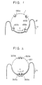
- FIG. 1 of the accompanying drawings, there is shown a rotary drum of an independent 4 head type for use in a conventional video tape recorder (VTR).
- a rotary drum 1 is rotated at a speed of 1800 r.p.m. in a direction shown by an arrow X, and a magnetic tape 2, a recording medium having a thickness of 19 ⁇ m is wound around approximately half the rotary drum 1 and runs at a speed of 3.335 cm/sec in a direction indicated by an arrow y in the VHS system.
- the rotary drum 1 is provided with four rotary video heads 100a, 100b, 100c and 100d having an azimuth angle of +6° or -6° on its periphery.
- the two heads 100a and 100b having a track width of 58 ⁇ m for covering a standard mode are correctly arranged in opposite positions on the rotary drum 1, and the two heads 100c and 100d having a track width of 19 ⁇ m for covering a triple speed mode are arranged on the rotary drum 1 in the same manner as the heads 100a and 100b.
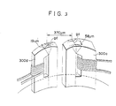
- FIGs. 2 and 3 there is shown another rotary drum of a combined 4 head type for use in a conventional VTR.
- a head 300a having a track width of 58 ⁇ m for standard mode record and reproduction and a head 300d having a track width of 19 ⁇ m for triple speed mode record and reproduction are mounted on a head base 203 at a distance of 1H, i.e., 370 ⁇ m to constitute combined heads.
- Heads 300b and 300c constitute combined heads in the same manner as the heads 300a and 300d.
- Two pairs of combined heads 300a, 300d, 300b and 300c are arranged in opposite positions on a rotary drum 201 as shown in Fig. 2.
- the heads 100a and 100b or 300a and 300b are operated, but the head 100c and 100d or 300c and 300d are just idled in an inoperative state.
- the heads 100c and 100d or 300c and 300d are operated, but the heads 100a and 100b or 300a and 300b are in the inoperative state.
- the azimuth angle of the heads 300a and 300c is determined to an equal angle +6° and the azimuth angle of the heads 300b and 300d is determined to an equal angle -6°
- the rotary drum of the combined 4 head type is widely used for a public VTR.
- a rotary transformer 315 includes four primary coils 315a, 315b, 315c and 315d and four secondary coils 315e, 315f, 315g and 315h corresponding to the respective primary coils 315a, 315b, 315c and 315d.
- the two video heads 300a and 300b for the standard mode are connected to the two primary coils 315a and 315b, respectively, while the two video heads 300c and 300d for the triple speed mode are connected to the two primary coils 315c and 315d, respectively.
- a pair of reproduction head amplifiers 309L and 309R corresponding to the respective video heads 300a and 300b are connected to one end of the secondary coils 315e and 315f, respectively.
- a record amplifier 312 is coupled to the other ends of the secondary coils 315e and 315f through a capacitor 316.
- a 2H (2 hour) record video signal is applied to the record amplifier 312 in a 2 hour standard mode recording.
- a pair of reproduction head amplifiers 310L and 310R corresponding to the respective video heads 300c and 300d are connected to one ends of the secondary coils 315g and 315h, respectively.
- Another record amplifier 313 is coupled to the other ends of the secondary coils 315g and 315h through another capacitor 317.
- a 6H (6 hour) record video signal is applied to the record amplifier 313 in a 6 hour triple speed mode recording.
- a pair of switches a1 and b1 are connected between the ends of the respective secondary coils 315e and 315f and ground, and a switch c1 is connected between the other ends of the secondary coils 315e and 315f and ground.
- a pair of switches a2 and b2 are connected between the end of the respective secondary coils 315g and 315h and ground, and a switch c2 is connected between the other ends of the secondary coils 315g and 315h and ground.
- a switch d1 selects one output of the reproduction head amplifiers 309L and 309R
- a switch d2 selects one output of the reproduction head amplifiers 310L and 310R
- a switch e1 selects one of 2H and 6H terminals connecting common terminals of the switches d1 and d2, that is, one output of the switches d1 and d2.
- a reproduction video signal is output from a common terminal of the switch e1.
- the switches a1 and b1 are closed and the switch c1 is open.
- the 2H record video signal is recorded on a magnetic tape through the record amplifier 312, the rotary transformer 315 and the video head 300a or 300b.
- the switches a1 and b1 are open and the switch c1 is closed.
- the switch d1 is turned over every field, and the switch e1 selects the 2H terminal.
- the reproduction video signal picked up by the video head 300a or 300b is output through the rotary transformer 315, the reproduction head amplifier 309L or 309R and the switches d1 and e1.
- the switches a2 and b2 are closed and the switch c2 is open.
- the 6H record video signal is recorded on the magnetic tape through the record amplifier 313, the rotary transformer 315 and the video head 300c or 300d.
- the switches a2 and b2 are open and the switch c2 is closed.
- the switch d2 is turned over every field, and the switch e1 selects the 6H terminal.
- the reproduction video signal picked up by the video head 300c or 300d is output through the rotary transformer 315, the reproduction head amplifier 310L or 310R and the switches d2 and e1.
- the tape running speed is changed depending on the standard and triple speed modes
- the track width is also changed depending on the standard and triple speed modes.
- the heads having the suitable different track widths are required for the standard and triple speed modes.
- the unoperated head 100c or 300c for the triple speed mode contacts the magnetic tape. Since the head generally projects 40 ⁇ m from the outer peripheral surface of the rotary drum, when the head contacts the magnetic tape, the head beats on the magnetic tape to give vibrations to the magnetic tape and to cause the vibrations in the directions of X-, Y- and Z-axes.
- the vibration in the tape running direction (X-axis) causes the signals on the magnetized magnetic tape to carry out a speed modulation which causes a strong jitter phenomenon and brings about jitters in the reproduced image.
- the unoperated head 100c or 300c beats the magnetic tape at a different portion to cause the vibrations, and as an inevitable result, the vibrations are transmitted to another head 200b or 300b via the magnetic tape.
- JP-A-61-90306 discloses a recording/reproducing head in which the secondary windings receiving signals from multiple magnetic cores in a combined head can be connected in series in a high speed mode. In a low speed mode the connection point is grounded.
- a recording/reproducing apparatus with a standard and a n-time speed mode for recording and reproducing comprising a driver device for at least one magnetic combined head mounted on a peripheral surface of a rotary drum, the combined head having an effective gap width and including at least two winding coils for head members for the magnetic recording and reproduction, the driver device comprising:
- EP-A-0427008 which falls under Art.54(3) EPC and is hence not relevant for to the question of inventive step, already describes with figure 4 a very similar arrangement, but wherein no short-circuiting of the unused head winding coil is realized; instead, this winding is left open.
- figure 9 this document already describes another very similar arrangement, in which such a short-circuiting is realized, but wherein no combined head with a changeable gap width is employed; instead different separate but neighbouring heads are used.
- the driver device can further include a video record amplifier arranged outside the rotary drum for amplifying a record video signal; a record amplifier arranged to rotate together with the rotary drum for further amplifying the record video signal amplified by the video record amplifier to output an amplified record video signal to the combined head; a reproduction head amplifier arranged to rotate together with the rotary drum for amplifying a reproduction video signal picked up by the combined head; a reproduction signal amplifier arranged outside the rotary drum for further amplifying the reproduction video signal amplified by the reproduction head amplifier to output an amplified reproduction video signal; and a rotary transformer for electrically connecting either the record amplifier with the video record amplifier, when recording, or the reproduction head amplifier with the reproduction signal amplifier, when reproducing, while the rotary drum is rotated.
- the second switch means includes a first switch arranged outside the rotary drum and interposed between ground and a connection point of the video record amplifier with the rotary transformer; a second switch arranged outside the rotary drum and interposed between ground and a connection point of the reproduction signal amplifier with the rotary transformer; a third switch arranged so as to rotate together with the rotary drum and interposed between the record amplifier and a connection point of the reproduction head amplifier with the rotary transformer; and a fourth switch arranged so as to rotate together with the rotary drum for changing a connection either between ground and a connection point of the reproduction head amplifier with the combined head or between ground and a connection point of the record amplifier with the combined head.
- the controller means further controls the second switch means so that either, the first switch is open, the second and third switches are closed, and the fourth switch connects between ground and the connection point of the reproduction head amplifier with the combined head when in the recording mode, or so that the first switch is closed, the second and third switches are open, and the fourth switch connects between ground and the connection point of the record amplifier with the combined head when in the reproducing mode.
- the driver device may be adapted for at least two magnetic combined head in which case it comprises at least two switch means one for each of the two combined head.
- a driver device of a magnetic head for use in magnetic record and reproduction free from the aforementioned defects and disadvantages of the prior art, which is capable of preventing problems at the contact surface between the head and the magnetic tape, removing jitters, improving the signal-to-noise ratio of the reproduction signal, improving adjacent crosstalk, reducing the manufacturing cost and simplifying the construction of the head driving circuit.
- a rotary drum 401 provided with a pair of combined heads 500e and 500f on opposite sides of its periphery for magnetic record and reproduction, the combined heads 500e and 500f being controlled by a driver device according to the present invention.
- a magnetic tape 402 as a recording medium is loaded around approximately half the rotary drum 401, and standard mode record and reproduction and triple speed mode record and reproduction are carried out by using the combined heads 500e and 500f.
- the combined head 500e having the same structure as the combined head 500f.
- the combined head 500e includes two head chips 501 and 511 composed of ferrite single crystal.
- the head chips 501 and 511 possess sliding surfaces 501a and 511a, respectively, to be contacted with the magnetic tape 402, having head gap portions 502 and 512, respectively, for directly carrying out the record and reproduction onto or off the magnetic tape 402.
- the widths of the head gap portions 502 and 512 are 39 ⁇ m and 19 ⁇ m, respectively.
- Numerals 503 and 513 denote respective glass reinforcement portions composed of a kind of adhesive for reinforcing the junctions of the head gap portions 502 and 512.
- the head chips 501 and 511 are formed with window portions 505 and 515, respectively, through which respective coils 504 and 514 wound around the respective chips 501 and 511 pass.
- the head chips 501 and 511 are also formed with hollow portions 506 and 516, respectively, on alternate sides of their contact surfaces for clearing the respective coils 514 and 504 wound around the other head chips 511 and 501 from contact with the respective head chips 501 and 511.
- the head chips 501 and 511 are secured to a head base 403 generally made of brass.
- the above-described two head chips 501 and 511 are put together so that the head gap portions 502 and 512 may be correctly aligned in their width direction, as shown in Fig. 7, and are then integrally adhered to each other.
- the thickness of the adhesive layer at the sliding surface is several ⁇ m, and, assuming that this several ⁇ m is ⁇ ⁇ m, the exact gap width of the head gap 502 becomes (39 - ⁇ ) ⁇ m.
- ⁇ 0.
- the coils 504 and 514 are fitted in the respective hollow portions 516 and 506 and are strongly adhered.
- each combined head 500e or 500f is provided with a head gap width of 39 ⁇ m of one head chip 501 and a head gap width of 19 ⁇ m of the other head chip 511, that is, a total head gap width of 58 ⁇ m.
- the width of the head gap portion 502 is determined to (39 - ⁇ ) ⁇ m counting on the thickness of the adhesive layer.
- the thickness of the adhesive layer is several ⁇ m, and the width of the head gap portions 502 or 512 may be determined to ⁇ 58 - (19 or 39) - several ⁇ ⁇ m.
- the curvatures of the sliding surfaces 501a and 511a of the head chips 501 and 511 are preferably equal, and this can be achieved by rubbing by means of a polishing tape to make uniform the curvatures after the two head chips 501 and 511 are adhered.
- the obtained combined heads 500e and 500f are correctly mounted onto the rotary drum 401 so that the combined heads may project 40 ⁇ m from the peripheral surface of the rotary drum 401 and be arranged in opposite positions at an exact angle of 180° around the center of the rotary drum 401.
- the magnetic tape 402 is loaded around approximately half the rotary drum 401, as shown in Fig. 5.
- both the head chips 501 and 511 are actuated. That is, the two coils 504 and 514 are connected by a switch so that the winding directions of the two coils 504 and 514 are the same so as to add the magnetic flux circulating through the head chips 501 and 511 to actuate the combined head as a head having a gap width equivalent to 58 ⁇ m.
- the head chip 511 In the triple speed mode recording or reproducing, only the head chip 511 is actuated so as to use the combined head as a head having a gap width of 19 ⁇ m.
- the coil 504 of the head chip 501 having a head gap of 39 ⁇ m is short-circuited in the rotary drum 401 to short-circuit the reproduction signal picked up by the head chip 501.
- the head gap portion 512 of the head chip 511 is actuated, and it is considered that the magnetic path of the head gap portion 512 is leaked to the adjacent head gap portion 502 having the gap width of 39 ⁇ m, as indicated by a broken arrow in Fig. 6.
- the coil 504 for the head gap width of 39 ⁇ m is directly short-circuited, hardly any leakage occurs.
- the combined head is actuated as a head having the gap width of exactly 19 ⁇ m.
- a driver device or more specifically, a driver circuit of combined heads shown in Figs. 5 to 7 for magnetic record and reproduction according to the present invention.
- one combined head 500e comprises two head members 501 and 511 having an azimuth angle of +6° and the other combined head 500f comprises two head members 601 and 611 having an azimuth angle of -6°.
- a rotary transformer 415 includes two primary coils 415a and 415b and two secondary coils 415c and 415d.
- a pair of reproduction head amplifiers 410a and 410b, arranged within the rotary drum 410, are connected between one terminal of the respective head members 501 and 601 and one end of the respective primary coils 415a and 415b of the rotary transformer 415.
- a pair of record amplifiers 411b and 411b, arranged within the rotary drum 410, are connected between one terminal of the respective head members 511 and 611 and one end of the respective primary coils 415a and 415b through respective electronic switches 416c and 416d.
- the other ends of the primary coils 415a and 415b are connected to ground.
- One of the terminals of either one of the head members 501 or 511 is selectively linked to ground by an electronic switch 416a, and either one of the terminals of either one of the head members 601 or 611 is selectively linked to ground by an electronic switch 416b.
- the electronic switches 416a, 416b, 416c and 416d constitute linked switches, as hereinafter described in detail.
- the other terminals of the head members 501 and 511 are coupled together, and the other terminals of the head members 601 and 611 are coupled together.
- An electronic switch 412a is interposed between one terminal of the head member 501 and the other terminals of the head members 501 and 511, and another electronic switch 412b is interposed between one terminal of the head member 601 and the other terminals of the head members 601 and 611.
- the two electronic switches 412a and 412b constitute linked switches for selectively short-circuiting the respective winding coils 504 and 514 of the respective head members 501 and 601 so as to change the head gap width to 58 ⁇ m (open) or 19 ⁇ m (closed) corresponding to the standard or triple speed mode.
- a pair of reproduction signal amplifiers 413a and 413b are connected to one end of the respective secondary coils 415c and 415d.
- An FM video record amplifier 414 is connected to the other ends of the secondary coils 415c and 415d through a capacitor 420.
- a record video signal is supplied to the FM video record amplifier 414.
- a pair of switches 417a and 417b are connected between one end of each of the respective secondary coils 415c and 415d and ground, and a switch 417c is connected between the other ends of the secondary coils 415c and 415d and ground.
- the switches 417a, 417b and 417c constitute linked switches, as hereinafter described in detail.
- a switch 418 selects one output of the reproduction signal amplifiers 413a and 413b, and a reproduction video signal is output from a common terminal of the switch 418.
- a numeral 401A designates the circuit components within the rotary drum 401, and a numeral 401B denotes the circuit components outside the rotary drum 401 (in a fixed drum portion).
- a controller 419 controls the switches depending on the standard and triple speed modes and the record and reproduction modes to be selected by an operator.
- the switches 412a and 412b are closed to short-circuit the head members 501 and 601 having the gap width of 39 ⁇ m.
- the switches 416a and 416b are turned over to connect one terminal of each of the head members 501 and 601 to ground, and the switches 416c and 416d are closed at the same time.
- the switches 417a and 417b are closed, but the switch 417c is open.
- the record video signal amplified in the record signal amplifier 414 drives the record amplifiers 411a and 411b through the rotary transformer 415 to actuate the head members 511 and 611 having the gap width of 19 ⁇ m, and the head members 511 and 611 record the video signal onto the magnetic tape 402.
- the head members 501 and 601 having the gap width of 39 ⁇ m are short-circuited, no record signal is applied to the same, and, since the short-circuited head members 501 and 601 have a large reluctance, the leaking magnetic flux of the head members 511 and 611 can not drive the head members 501 and 601.
- the switches 412a and 412b are still closed.
- the switches 416a and 416b are turned over to connect one terminal of each of the head members ill and 611 to ground, and the switches 416c and 416d are open at the same time. Further, the switches 417a and 417b are simultaneously open, and the switch 417c is closed.
- the respective slight reproduction video signals picked up from the magnetic tape 402 by the respective head members 511 and 611 pass through the respective switches 412a and 412b and are amplified in the respective reproduction head amplifiers 410a and 410b.
- the respective amplified reproduction video signals are fed to the respective reproduction signal amplifiers 413a and 413b via the rotary transformer 415 and are amplified again in the reproduction signal amplifiers 413a and 413b.
- the amplified reproduction video signals output from the respective reproduction signal amplifiers 413a and 413b are switched every field by the switch 418, and frame video signals having a certain continuous level are output from the common terminal of the switch 418.
- the reproduction video signals picked up by the head members 501 and 601 are not applied to the rotary transformer 415. Since the short-circuited head members 501 and 601 have a large reluctance, the leaking magnetic flux of the reproduction FM video signals from the head members 501 and 601 to the head members 511 and 611 can be almost ignored.
- the switches 412a and 412b are open.
- the switches 416a and 416b are turned over to connect one terminal of each of the head members 501 and 601 to ground, and the switches 416c and 416d are closed at the same time.
- the switches 417a and 417b are closed, but the switch 417c is open. In this mode, the operation is carried out in the same manner as the triple speed recording described above.
- the adhesive layer portion of ⁇ ⁇ m at the adhered surface between the two head members does not cause any problems.
- the switches 412a and 412b are still open.
- the switches 416a and 416b are turned over to connect one terminal of each of the head members 511 and 611 to ground, and the switches 416c and 416d are open at the same time.
- the switches 417a and 417b are simultaneously open, and the switch 417c is closed.
- the operation is carried out in the same manner as the triple speed reproduction described above, and the combined head is actuated as a head having a gap width of 58 ⁇ m in the same manner as the standard speed recording.
- a driver device of the present invention drives combined heads mounted on the peripheral surface of a rotary drum.
- Each combined head includes at least two head members contacted with one another for magnetic recording and reproduction, each head member including a winding coil and a gap having a gap width.
- Each combined head is formed with a continuous gap composed of the gaps of the head members, and the gap width of the continuous gap of the combined head is composed of the gap widths of the head members.
- a magnetic reccording and reproduction apparatus such as a VTR
- circuits rotating together with a rotary drum and circuits arranged outside the rotary drum can be electrically connected.
- switches for short-circuiting the winding coils of the head members are arranged within the rotary drum, and output signals of the combined heads are amplified within the rotary drum.
- the amplified output signals are output to the outside of the rotary drum through the rotary transformer. In this case, even when obstructive signals such as noise are added to the rotary transformer, the influences can be ignored and so improve the S/N ratio.
- the number of the heads arranged on the rotary drum 401 is reduced to half, and as shown in Fig. 5, when one combined head 500e is contacted with the running magnetic tape 402, the other combined head 500f does not contact with the magnetic tape 402 and thus prevents the tape beating. Further, since there is only one gap portion, the stuffing and smudging can be largely reduced, and the contact between the gap portion and the magnetic tape becomes uniform and stable. Hence, the slide contact noise is largely reduced to enable the reduction of any jitter.
- the winding coils of the head members having the gap width of 39 ⁇ m are directly short-circuited by the electronic switches mounted within the drum, the reluctance of the short-circuited head members is high, and no leakage of the magnetic flux from the head members having the gap width of 39 ⁇ m to the head members having the gap width of 19 ⁇ m is caused which prevents the generation of crosstalk components.
- the processing of the drum for mounting the heads and the mounting operation of the heads are also reduced to half.
- the electronic switches analog switches are possible
- the electronic switches can be composed of MOS ICs of a low power consumption type, a power supply system by electromagnetic coupling of the rotary transformer 415 is possible.
- the number of the combined heads is reduced, and the standard and triple speed modes and the recording and reproducing modes can be changed by switches. Hence, the structure of the driver device can be simplified and manufactured at a low cost.
- the gap widths can not be restricted to these values and can, of course, be changed.
- At least three head members can be contacted with one another to prepare a combined head, and at least three kinds of gap widths for the standard and triple speed recording and reproduction modes and a particular reproduction mode can be determined.
- the position of the winding coil can be changed to any position of the head chip as long as the magnetic flux is circulated in a closed loop.
- the head chips can be contacted with each other by a sputtering method without using an adhesive.
- the head width (corresponding to 39 ⁇ m) of a supplemented head member can be reduced by that amount.
- the switching circuits shown in Fig. 8 are only examples and thus the switching circuits are not restricted to these circuits.
- the winding coil direction and the driving current are determined so that the magnetic flux of one head member such as a supplemental head member may be added to that of the other head member.
- the triple speed mode operation only one head member such as a head member having a narrow width is actuated and the other head member such as an unoperated head member is short-circuited to reduce the crosstalk generated by the unoperated head member in the same manner as described above with the same effects.
- the combined head can be changed to a suitable head width to remove crosstalk components of an adjacent track of a magnetic tape, enabling record and reproduction operations with an excellent S/N ratio. Further, the number of the heads can be reduced to at most half as compared with a conventional combined head system, and hence the tape beating by an unoperated head or heads will not be caused.
- the contact condition between the gap portion and the running tape can readily be kept uniform and stable in order to reduce the slide contact noise to half and to obtain high quality images with less jitter in the recording and reproducing modes.
- the combined head is operated as a head having a narrow gap width, since the winding coil of the unoperated head member mechanically contacting and sliding with the magnetic tape is short-circuited within the rotary drum, the short-circuited head member has a large reluctance to enable the reduction of the crosstalk signals to half.
- the gains of the reproduction head amplifiers positioned within the rotary drum can be calculated in consideration of the balance with reference to the reproduction signal amplifiers of the rear stage and can thus be designed without consideration of the S/N ratio.
- the winding coil grooves of the rotary transformer are reduced to half, and in addition to the reduction of the cost as the rotary transformer is arranged within the limited rotary drum, the designing surplus can be taken in the combined inductance, the leakage inductance and the combine factor to enable a signal transmittance with an excellent S/N ratio.
- the head structure by the head structure, the change in the coil winding system within the rotary drum and the reduction of the winding coil grooves of the rotary transformer, the signal quality of the high quality VTR can be largely improved.
Landscapes
- Recording Or Reproducing By Magnetic Means (AREA)
Claims (5)
- Aufnahme- und Wiedergabegerät mit einem Normal- und einem n-fachen Geschwindigkeitsbetrieb bei Aufnahme und Wiedergabe, mit einer Treibervorrichtung für wenigstens einen magnetischen Kombinationskopf (500e; 500f), der auf einer äußeren Oberfläche einer Drehtrommel (401) montiert ist, wobei der Kombinationskopf (500e; 500f) eine effektive Luftspaltweite aufweist und wenigstens zwei Wicklungen (501, 511, 601, 611) für Kopfglieder für die magnetische Aufnahme und Wiedergabe enthält, wobei die Treibervorrichtung ausgestattet ist mit:in der Drehtrommel (401) vorgesehenen Schaltmitteln (412a, 412b), die mit den Wicklungen (501, 601, 511, 611) zur Änderung der effektiven Luftspaltbreite durch selektives Kurzschließen wenigstens einer der Wicklungen (500e; 500f) verbunden sind, so daß die effektive Spaltbreite des Kombinationskopfes entweder in eine erste effektive Spaltbreite für einen n- (n ist ein ganze Zahl von wenigstens zwei) fachen Geschwindigkeitsbetrieb durch Schließen des Schaltmittels (412a, 412b) geändert wird, oder in eine zweite effektive Spaltbreite für einen Normalgeschwindigkeitsbetrieb durch Öffnen des Schaltmittels (412a, 412b); und mitSteuermitteln (417) entweder zum Schließen des Schaltmittels im n- fachen Geschwindigkeitsbetrieb bei Aufnahme und Wiedergabe oder zum Öffnen des Schaltmittels (412a, 412b) im Normalgeschwindigkeitsbetrieb bei Aufnahme und Wiedergabe, so daß wenigstens eine der Wicklungen (500e; 500f) während der Aufnahme und Wiedergabe kurzgeschlossen ist.
- Gerät nach Anspruch 1, das weiterhin ausgestattet ist mit:zweiten Schaltmitteln (416a- d, 417a-c) einschließlich wenigstens zweier Schalter (416a- d, 417a-c) mit ersten und zweiten Schaltzuständen, zur Auswahl entweder des Aufnahmebetriebs, wenn die Schalter den ersten Schaltzustand einnehmen, um ein Videoaufnahmesignal an den Kombinationskopf (500e; 500f) zu liefern oder des Wiedergabebetriebs, wenn die Schalter (416a- d, 417a- c) den zweiten Schaltzustand einnehmen, um ein Videowiedergabesignal aus dem Kombinationskopf zu empfangen,wobei die Steuermittel (417) die Schalter (416a- d, 417a- c) befähigen, entweder den ersten Schaltzustand im Aufnahmebetrieb oder den zweiten Schaltzustand im Wiedergabebetrieb einzunehmen.
- Gerät nach Anspruch 2, das weiterhin ausgestattet ist mit:einem außerhalb der Drehtrommel (401) zur Verstärkung eines Videoaufnahmesignals vorgesehenen Videoaufnahmeverstärker (414);einem sich gemeinsam mit der Drehtrommel (401) drehenden Aufnahmeverstärker (411a, b), um das vom Videoaufnahmeverstärker (414) zur Ausgabe eines verstärkten Videoaufnahmesignals für den Kombinationskopf (500e; 500f) verstärkte Videoaufnahmesignal weiter zu verstärken;einem sich gemeinsam mit der Drehtrommel (401) drehenden Vorverstärker (410a, b), um ein vom Kombinationskopf (500e; 500f) empfangenes Videowiedergabesignal zu verstärken;einem außerhalb der Drehtrommel (401) angeordneten Wiedergabesignalverstärker (413a, b), der das vom Vorverstärker (410a, b) verstärkte Videowiedergabesignal weiterverstärkt, um ein verstärktes Videowiedergabesignal abzugeben; und miteinem Drehtransformator (415) zur elektrischen Verbindung entweder des Aufnahmeverstärkers (411a, b) mit dem Videoaufnahmeverstärker (414) im Aufnahmebetrieb oder mit dem Vorverstärker (410a, b) mit dem Wiedergabeverstärker (413a, b) im Wiedergabebetrieb, während sich die Drehtrommel (401) dreht,wobei die zweiten Schaltmittel ausgestattet sind mit:einem ersten außerhalb der Drehtrommel (401) zwischen Masse und einem Verbindungspunkt des Videoaufnahmeverstärkers (414) mit dem Drehtransformator (415) eingefügten Schalter (417c);einem zweiten außerhalb der Drehtrommel (401) und zwischen Masse und einem Verbindungspunkt des Wiedergabesignalverstärkers (413a, b) mit dem Drehtransformator (415) eingefügten Schalter (417a, b);einem dritten sich gemeinsam mit der Drehtrommel (401) drehenden und zwischen den Aufnahmeverstärker (411a, b) und einem Verbindungspunkt des Vorverstärker (410a, b) mit dem Drehtransformator (415) eingefügten Schalter (416c, d); und miteinem vierten sich gemeinsam mit der Drehtrommel (401) drehenden Schalter (416a, b) zur Änderung einer Verbindung entweder zwischen Masse und einem Verbindungspunkt des Vorverstärkers (410a, b) mit dem Kombinationskopf (500e; 500f) oder zwischen Masse und einem Verbindungspunkt des Aufnahmeverstärkers (411a, b) mit dem Kombinationskopf (500e; 500f),wobei das Steuermittel (417) die zweiten Schaltmittel (416a- d, 417a- c) entweder so steuert, daß im Aufnahmebetrieb der erste Schalter (417c) geöffnet ist, der zweite und dritte Schalter (417a, b; 416c, d) geschlossen und der vierte Schalter (416a, b) eine Verbindung zwischen Masse und dem Verbindungspunkt des Vorverstärkers (410a, b) mit dem Kombinationskopf (500e; 500f) herstellt, oder derart, daß im Wiedergabebetrieb der erste Schalter (417) geschlossen ist, der zweite und dritte Schalter (417a, b; 416c, d) offen ist und der vierte Schalter (416a, b) eine Verbindung zwischen Masse und dem Verbindungspunkt des Aufnahmeverstärkers (411a, b) mit dem Kombinationskopf (500e; 500f) herstellt.
- Gerät nach Anspruch 1, 2, oder 3 für wenigstens zwei magnetische Aufnahme- Wiedergabeköpfe, das wenigstens zwei der Schaltmittel enthält, eines für jeden der beiden Aufnahme-Wiedergabeköpfe.
- Gerät nach Anspruch 1, das einen einzelnen Schalter (416a, b) enthält, der die Kopfseite des Aufnahmeverstärkers (411a, b) im Wiedergabebetrieb oder den Vorverstärker (410a, b) im Aufnahmebetrieb selektiv mit Masse verbindet.
Applications Claiming Priority (2)
| Application Number | Priority Date | Filing Date | Title |
|---|---|---|---|
| JP2197484A JPH0482006A (ja) | 1990-07-23 | 1990-07-23 | 磁気記録再生用磁気ヘッドの駆動装置 |
| JP197484/90 | 1990-07-23 |
Publications (3)
| Publication Number | Publication Date |
|---|---|
| EP0468744A2 EP0468744A2 (de) | 1992-01-29 |
| EP0468744A3 EP0468744A3 (en) | 1992-07-08 |
| EP0468744B1 true EP0468744B1 (de) | 1997-03-05 |
Family
ID=16375242
Family Applications (1)
| Application Number | Title | Priority Date | Filing Date |
|---|---|---|---|
| EP91306697A Expired - Lifetime EP0468744B1 (de) | 1990-07-23 | 1991-07-23 | Magnetkopftreibervorrichtung für Magnetaufzeichnung und -wiedergabe |
Country Status (4)
| Country | Link |
|---|---|
| US (1) | US5311377A (de) |
| EP (1) | EP0468744B1 (de) |
| JP (1) | JPH0482006A (de) |
| DE (1) | DE69124862T2 (de) |
Families Citing this family (4)
| Publication number | Priority date | Publication date | Assignee | Title |
|---|---|---|---|---|
| DE4221237A1 (de) * | 1992-06-27 | 1994-01-05 | Philips Patentverwaltung | Schaltungsanordnung zur Aufzeichnung von Datensignalen |
| JP3086768B2 (ja) * | 1993-06-30 | 2000-09-11 | 株式会社東芝 | 磁気記録再生装置用増幅回路 |
| US5712739A (en) * | 1993-11-08 | 1998-01-27 | Kabushiki Kaisha Toshiba | Magnetic disk drive system with a composite head unit including a magnetoresistive read only head and an inductive write only head |
| JP2869695B2 (ja) * | 1993-12-08 | 1999-03-10 | ニチアス株式会社 | 軽量有機発泡体の製造方法 |
Citations (4)
| Publication number | Priority date | Publication date | Assignee | Title |
|---|---|---|---|---|
| JPS59175004A (ja) * | 1983-03-23 | 1984-10-03 | Toshiba Corp | 磁気記録再生装置 |
| JPS60242502A (ja) * | 1984-05-16 | 1985-12-02 | Hitachi Ltd | 回転ヘツド型記録再生装置 |
| JPS61246950A (ja) * | 1985-04-25 | 1986-11-04 | Toshiba Corp | 磁気記録再生装置 |
| JPS6390110A (ja) * | 1986-10-02 | 1988-04-21 | Mitsubishi Electric Corp | ロ−タリトランスのクロスト−ク低減装置 |
Family Cites Families (13)
| Publication number | Priority date | Publication date | Assignee | Title |
|---|---|---|---|---|
| US3813693A (en) * | 1970-08-28 | 1974-05-28 | Ampex | Magnetic head with protective pockets of glass adjacent the corners of the gap |
| US4302790B1 (en) * | 1979-04-11 | 1999-06-08 | Eastman Kodak Co | Magnetic recording head with effective magnetic gap length less than about 15mu inches |
| US4520405A (en) * | 1981-06-22 | 1985-05-28 | Victor Company Of Japan, Ltd. | Insert recording system for a video signal |
| JPS5965961A (ja) * | 1982-10-06 | 1984-04-14 | Matsushita Electric Ind Co Ltd | ビデオテ−プレコ−ダ |
| JPS6013303A (ja) * | 1983-07-05 | 1985-01-23 | Olympus Optical Co Ltd | 回転ヘツド装置 |
| JPS60242501A (ja) * | 1984-05-16 | 1985-12-02 | Hitachi Ltd | 回転ヘツドシリンダ |
| JPS6190307A (ja) * | 1984-10-08 | 1986-05-08 | Canon Inc | ヘツド装置 |
| JPS6190306A (ja) * | 1984-10-08 | 1986-05-08 | Canon Inc | 記録または再生装置 |
| KR910000367B1 (ko) * | 1985-12-18 | 1991-01-24 | 미쓰비시전기 주식회사 | 영상기록 재생장치 |
| KR910006487B1 (ko) * | 1986-06-26 | 1991-08-26 | 미쓰비시덴기 가부시기가이샤 | 영상 재생 장치 |
| JPS6374101A (ja) * | 1986-09-17 | 1988-04-04 | Mitsubishi Electric Corp | 回転ヘツド型磁気記録再生装置 |
| DE277000T1 (de) * | 1987-01-27 | 1988-11-24 | Victor Company Of Japan, Ltd., Yokohama, Kanagawa | Geraet zur magnetischen aufzeichnung und/oder wiedergabe. |
| DE69031157T2 (de) * | 1989-11-10 | 1998-01-29 | Mitsubishi Electric Corp | Rotierender Magnetkopf-Zusammenbau |
-
1990
- 1990-07-23 JP JP2197484A patent/JPH0482006A/ja active Pending
-
1991
- 1991-07-22 US US07/733,843 patent/US5311377A/en not_active Expired - Lifetime
- 1991-07-23 EP EP91306697A patent/EP0468744B1/de not_active Expired - Lifetime
- 1991-07-23 DE DE69124862T patent/DE69124862T2/de not_active Expired - Fee Related
Patent Citations (4)
| Publication number | Priority date | Publication date | Assignee | Title |
|---|---|---|---|---|
| JPS59175004A (ja) * | 1983-03-23 | 1984-10-03 | Toshiba Corp | 磁気記録再生装置 |
| JPS60242502A (ja) * | 1984-05-16 | 1985-12-02 | Hitachi Ltd | 回転ヘツド型記録再生装置 |
| JPS61246950A (ja) * | 1985-04-25 | 1986-11-04 | Toshiba Corp | 磁気記録再生装置 |
| JPS6390110A (ja) * | 1986-10-02 | 1988-04-21 | Mitsubishi Electric Corp | ロ−タリトランスのクロスト−ク低減装置 |
Also Published As
| Publication number | Publication date |
|---|---|
| DE69124862T2 (de) | 1997-06-26 |
| DE69124862D1 (de) | 1997-04-10 |
| US5311377A (en) | 1994-05-10 |
| EP0468744A3 (en) | 1992-07-08 |
| EP0468744A2 (de) | 1992-01-29 |
| JPH0482006A (ja) | 1992-03-16 |
Similar Documents
| Publication | Publication Date | Title |
|---|---|---|
| EP0468744B1 (de) | Magnetkopftreibervorrichtung für Magnetaufzeichnung und -wiedergabe | |
| EP0554867B1 (de) | Magnetisches Aufzeichnungs-/Wiedergabegerät | |
| EP0427008B1 (de) | Rotierender Magnetkopf-Zusammenbau | |
| US5953482A (en) | Magnetic recording/reproducing apparatus with the recording/reproducing heads preceding the erasing heads | |
| US5249087A (en) | Rotating head amplifier for vcr | |
| JPS5845082B2 (ja) | 回転トランス装置 | |
| JP2795973B2 (ja) | 回転磁気ヘッド装置 | |
| US6222701B1 (en) | Magnetic head with (411) plane single crystal ferrite medium facing surface and (122) plane gap surface | |
| JP2732405B2 (ja) | 磁気記録再生ヘッド | |
| JP2595097B2 (ja) | 回転磁気ヘッド装置 | |
| US5721653A (en) | Head base for giving an azimuth angle to a magnetic gap of a head for use in a video cassette recorder | |
| JPH06101104B2 (ja) | 磁気ヘッド装置 | |
| USRE39029E1 (en) | Magnetic recording/reproducing apparatus with the recording/reproducing heads preceding the erasing heads | |
| JPH0416241Y2 (de) | ||
| JP3603538B2 (ja) | 単結晶フェライト磁気ヘッド | |
| KR100202487B1 (ko) | 회전트랜스가 없는 기록재생장치의 헤드드럼 | |
| JPH01312703A (ja) | 磁気消去回路 | |
| JPS6316016Y2 (de) | ||
| JPS6233311A (ja) | 磁気ヘツド | |
| JPH08315307A (ja) | 磁気記録データの再生装置 | |
| JPH0525042Y2 (de) | ||
| JPH0614437Y2 (ja) | 回転トランス装置 | |
| JPH0366014A (ja) | 複合型薄膜磁気ヘッド | |
| JPH0520624A (ja) | 磁気ヘツドコア | |
| JPH03154209A (ja) | 磁気記録再生用複合ヘッド |
Legal Events
| Date | Code | Title | Description |
|---|---|---|---|
| PUAI | Public reference made under article 153(3) epc to a published international application that has entered the european phase |
Free format text: ORIGINAL CODE: 0009012 |
|
| AK | Designated contracting states |
Kind code of ref document: A2 Designated state(s): DE FR GB |
|
| PUAL | Search report despatched |
Free format text: ORIGINAL CODE: 0009013 |
|
| AK | Designated contracting states |
Kind code of ref document: A3 Designated state(s): DE FR GB |
|
| 17P | Request for examination filed |
Effective date: 19920814 |
|
| 17Q | First examination report despatched |
Effective date: 19940419 |
|
| GRAG | Despatch of communication of intention to grant |
Free format text: ORIGINAL CODE: EPIDOS AGRA |
|
| GRAH | Despatch of communication of intention to grant a patent |
Free format text: ORIGINAL CODE: EPIDOS IGRA |
|
| GRAH | Despatch of communication of intention to grant a patent |
Free format text: ORIGINAL CODE: EPIDOS IGRA |
|
| GRAA | (expected) grant |
Free format text: ORIGINAL CODE: 0009210 |
|
| AK | Designated contracting states |
Kind code of ref document: B1 Designated state(s): DE FR GB |
|
| REF | Corresponds to: |
Ref document number: 69124862 Country of ref document: DE Date of ref document: 19970410 |
|
| ET | Fr: translation filed | ||
| PLBE | No opposition filed within time limit |
Free format text: ORIGINAL CODE: 0009261 |
|
| STAA | Information on the status of an ep patent application or granted ep patent |
Free format text: STATUS: NO OPPOSITION FILED WITHIN TIME LIMIT |
|
| 26N | No opposition filed | ||
| PGFP | Annual fee paid to national office [announced via postgrant information from national office to epo] |
Ref country code: FR Payment date: 20010712 Year of fee payment: 11 |
|
| PGFP | Annual fee paid to national office [announced via postgrant information from national office to epo] |
Ref country code: DE Payment date: 20010716 Year of fee payment: 11 |
|
| PGFP | Annual fee paid to national office [announced via postgrant information from national office to epo] |
Ref country code: GB Payment date: 20010718 Year of fee payment: 11 |
|
| REG | Reference to a national code |
Ref country code: GB Ref legal event code: IF02 |
|
| PG25 | Lapsed in a contracting state [announced via postgrant information from national office to epo] |
Ref country code: GB Free format text: LAPSE BECAUSE OF NON-PAYMENT OF DUE FEES Effective date: 20020723 |
|
| PG25 | Lapsed in a contracting state [announced via postgrant information from national office to epo] |
Ref country code: DE Free format text: LAPSE BECAUSE OF NON-PAYMENT OF DUE FEES Effective date: 20030201 |
|
| GBPC | Gb: european patent ceased through non-payment of renewal fee |
Effective date: 20020723 |
|
| PG25 | Lapsed in a contracting state [announced via postgrant information from national office to epo] |
Ref country code: FR Free format text: LAPSE BECAUSE OF NON-PAYMENT OF DUE FEES Effective date: 20030331 |
|
| REG | Reference to a national code |
Ref country code: FR Ref legal event code: ST |