EP0468795A2 - Gepulster Laser - Google Patents
Gepulster Laser Download PDFInfo
- Publication number
- EP0468795A2 EP0468795A2 EP91306803A EP91306803A EP0468795A2 EP 0468795 A2 EP0468795 A2 EP 0468795A2 EP 91306803 A EP91306803 A EP 91306803A EP 91306803 A EP91306803 A EP 91306803A EP 0468795 A2 EP0468795 A2 EP 0468795A2
- Authority
- EP
- European Patent Office
- Prior art keywords
- light
- laser
- pumping
- pulse
- deflector
- Prior art date
- Legal status (The legal status is an assumption and is not a legal conclusion. Google has not performed a legal analysis and makes no representation as to the accuracy of the status listed.)
- Granted
Links
Images


Classifications
-
- H—ELECTRICITY
- H01—ELECTRIC ELEMENTS
- H01S—DEVICES USING THE PROCESS OF LIGHT AMPLIFICATION BY STIMULATED EMISSION OF RADIATION [LASER] TO AMPLIFY OR GENERATE LIGHT; DEVICES USING STIMULATED EMISSION OF ELECTROMAGNETIC RADIATION IN WAVE RANGES OTHER THAN OPTICAL
- H01S3/00—Lasers, i.e. devices using stimulated emission of electromagnetic radiation in the infrared, visible or ultraviolet wave range
- H01S3/10—Controlling the intensity, frequency, phase, polarisation or direction of the emitted radiation, e.g. switching, gating, modulating or demodulating
- H01S3/11—Mode locking; Q-switching; Other giant-pulse techniques, e.g. cavity dumping
- H01S3/1123—Q-switching
- H01S3/117—Q-switching using intracavity acousto-optic devices
-
- H—ELECTRICITY
- H01—ELECTRIC ELEMENTS
- H01S—DEVICES USING THE PROCESS OF LIGHT AMPLIFICATION BY STIMULATED EMISSION OF RADIATION [LASER] TO AMPLIFY OR GENERATE LIGHT; DEVICES USING STIMULATED EMISSION OF ELECTROMAGNETIC RADIATION IN WAVE RANGES OTHER THAN OPTICAL
- H01S3/00—Lasers, i.e. devices using stimulated emission of electromagnetic radiation in the infrared, visible or ultraviolet wave range
- H01S3/10—Controlling the intensity, frequency, phase, polarisation or direction of the emitted radiation, e.g. switching, gating, modulating or demodulating
- H01S3/106—Controlling the intensity, frequency, phase, polarisation or direction of the emitted radiation, e.g. switching, gating, modulating or demodulating by controlling devices placed within the cavity
- H01S3/108—Controlling the intensity, frequency, phase, polarisation or direction of the emitted radiation, e.g. switching, gating, modulating or demodulating by controlling devices placed within the cavity using non-linear optical devices, e.g. exhibiting Brillouin or Raman scattering
-
- H—ELECTRICITY
- H01—ELECTRIC ELEMENTS
- H01S—DEVICES USING THE PROCESS OF LIGHT AMPLIFICATION BY STIMULATED EMISSION OF RADIATION [LASER] TO AMPLIFY OR GENERATE LIGHT; DEVICES USING STIMULATED EMISSION OF ELECTROMAGNETIC RADIATION IN WAVE RANGES OTHER THAN OPTICAL
- H01S3/00—Lasers, i.e. devices using stimulated emission of electromagnetic radiation in the infrared, visible or ultraviolet wave range
- H01S3/05—Construction or shape of optical resonators; Accommodation of active medium therein; Shape of active medium
- H01S3/08—Construction or shape of optical resonators or components thereof
- H01S3/08018—Mode suppression
- H01S3/0804—Transverse or lateral modes
- H01S3/0805—Transverse or lateral modes by apertures, e.g. pin-holes or knife-edges
Definitions
- the present invention relates to a pulse laser used in, e.g., a YAG-laser and, more particularly, to an apparatus for instantaneously switching an optical path of light emitted from a laser medium by a light deflector to extract the switched light outside a laser resonator, and outputting the light as pulse laser light.
- an A/O or E/O device is used as a deflector for these oscillator.
- an ultrasonic wave is supplied to an acoustooptic crystal such as LiNbO3, PbMoO4, TeO2, or the like to bend emission light.
- the ultrasonic wave is repetitively supplied to instantaneously extract emission light from the laser medium outside a laser resonator at the same period as the ultrasonic wave, thereby outputting pulse laser light.
- a voltage is applied to an electrooptic crystal such as LiNbO3, KDP, ADP, or the like to bend emission light. The voltage is repetitively applied to instantaneously extract emission light, thereby outputting pulse laser light.
- the conventional light deflector supplies an ultrasonic wave or applies an electric field to an optical crystal, its high-speed operation as an optical switch for switching emission light is limited.
- a beam of the emission light generated by exciting the laser medium is bent by the light-light deflection member to be instantaneously extracted outside the laser resonator, and upon repetition of this operation, laser pulses are output. Deflection of the beam of the emission light by the light-light deflection member is performed by controlling the radiation amount of pumping light from the pumping means.
- a speed determining the pulse width in the ON state is defined as a switching speed.
- the pulse laser of the present invention high-speed switching can be attained in synchronism with pumping light, and as a result, a laser pulse having an extremely small pulse width and large peak power can be output.
- the deflector comprises a light-light deflection member in which a refractive index change region is formed by pumping light radiated from a direction perpendicular to the optical path of the emission light to bend the emission light, and a pumping source for radiating the pumping light into the light-light deflection member.
- a beam of the emission light generated by exciting the laser medium is deflected by the light-light deflection member to be instantaneously extracted outside the laser resonator, and upon repetition of this operation, a laser pulse is output.
- Deflection control of emission light by the light-light deflection member is attained by repeating an ON state wherein the pumping source is turned on to form the refractive index change region in the light-light deflection member so as to bend the beam of the emission light, and an OFF state wherein the pumping source is turned off to cause the emission light to go straight through the light-light deflection member.
- a speed determining the pulse width of the ON state is defined as a switching speed.
- the pulse laser may comprise a Q-switch, a cavity damper, or a mode locker having the deflector.
- the laser medium is kept excited in the laser resonator, and emission light is caused to fall outside its optical path to increase a loss.
- the pumping light for the light-light deflection member is set in the ON state to deflect the beam of the emission light, and to abruptly decrease the loss, thereby extracting laser light in a high-output state outside the laser resonator.
- the ON/OFF operations of the pumping source are repeated to output laser pulses.
- pumping light is set in the ON state to cause emission light to escape outside the resonator by deflection so as to increase a loss.
- the loss is abruptly decreased by the next OFF state of the pumping light to oscillate the emission light. Upon repetition of these operations, laser pulses can be output.
- the laser medium is kept excited, and emission light is reciprocated in the laser resonator to keep a laser oscillation state, thereby increasing internal energy.
- pumping light for the light-light deflection member is set in the ON state to instantaneously extract the accumulated energy outside the resonator, thereby oscillating laser light.
- the ON/OFF operations of the pumping source are repeated to output pulse laser beams.
- laser pulses may be output in the OFF state of the pumping light like in the Q-switch.
- the deflector serves as opening/closing means for a mode synchronization shutter. More specifically, the shutter is opened/closed in the ON/OFF states of pumping light, and pulse laser light is output in the open or closed state.
- a portion of the laser medium may be used commonly as the light-light deflection member to simplify the structure of the apparatus.
- the refractive index of the light-light deflection member is changed depending on the intensity of pumping light
- the light-light deflection member preferably comprises a mask formed with an opening for defining the radiation region or the refractive index change region capable of bending the beam of the emission light on the side of a surface irradiated with pumping light.
- emission light can be deflected in a desired bending state in accordance with the intensity of pumping light or a mask pattern.
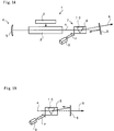
- a pulse laser according to the first embodiment of the present invention will be described below.
- the pulse laser 1 is a so-called YAG laser.
- a lamp sealed with, e.g., xenon gas is used as an excitation medium 2
- a Y 3-X Nd X Al5O12 crystal is used as a laser medium 3 for emitting stimulated light A upon excitation of the excitation medium 2.
- a Fabry-Pérot resonator comprising back and front mirrors 5 and 6 is used as a laser resonator 4 for oscillating the emission light A.
- the back mirror 5 of the resonator 4 comprises a total reflection mirror
- the front mirror 6 comprises a partial transmission mirror as an output mirror.
- the front mirror 6 is inclined with respect to the back mirror 5 not to normally constitute a laser cavity.
- a Q-switch 7 is inserted on an optical path between the laser medium 3 and the front mirror 6.
- the Q-switch 7 comprises a light-light deflector 8 as a light-light deflecting member, and a pumping source 9 for radiating pumping light P onto the deflector 8.
- the pumping source 9 comprises a pulse laser or an LED which can be repetitively turned on/off at high speed.
- a refractive index change region 10 equivalent to a prism can be formed in the light-light deflector 8. More specifically, an ON state of the pumping light P wherein the pumping source 9 is turned on to form the refractive index change region 10 in the light-light deflector 8 so as to bend the optical path of the emission light A, and an OFF state of the pumping light P wherein the pumping source 9 is turned off to cause the emission light A to go straight through the light-light deflector 8, can be repeated at high speed.
- the laser medium 3 excited by the excitation medium 2 induces the emission light A.
- the emission light A is reflected by the back mirror 5, reaches the front mirror 6, and falls outside the optical path. More specifically, the emission light A is escaped to suppress laser oscillation, while excitation energy from the excitation medium 2 is accumulated in the laser medium 3 as an inverted population, thereby forming a high-loss state of the laser resonator 4.
- the pumping light P having a predetermined light intensity is radiated onto the light-light deflector 8 to form the equivalent prism in the light-light deflector (ON state).
- the emission light A is deflected by the prism, and a cavity is formed between the mirrors 5 and 6.
- the resonator 4 is instantaneously set in a low-loss state, and the energy accumulated as the inverted population is immediately converted into photon energy in the resonator 4, thus causing laser oscillation.
- the above-mentioned ON and OFF states are repeated by turning on/off the pumping source 9, and the photon energy is output from the front mirror 6 as pulse laser light B.
- the laser light B is output by constituting the equivalent prism in the light-light deflector 8 upon radiation of the pumping light P, and the characteristic of output pulses are determined by the ON/OFF operations of the pumping source 9, i.e., the ON/OFF states (switching) of the pumping light P.
- a speed determining the pulse width of the ON state corresponds to a switching speed. Since switching is optically performed, a high-speed operation can be attained, and as a result, the laser light B having a small pulse width can be obtained. Since the pulse width can be decreased, the laser light B having a large peak value can be obtained.
- pulse oscillation of the laser light B can be easily controlled since it is obtained in synchronism with the ON/OFF operations of the pumping source 9, i.e., the ON/OFF states of the pumping light P.
- Fig. 1B shows a case wherein the ON/OFF states of the pumping light P for the light-light deflector 8 are reversed. More specifically, the mirrors 5 and 6 are arranged to be parallel to each other so as to constitute a cavity in the OFF state of the pumping light P.
- the pumping light P is initially set in the ON state, and the equivalent prism is formed in the light-light deflector 8 to deflect the emission light A, so that the emission light A falls outside the optical path to suppress laser oscillation. From this state, the pumping light P is set in the OFF state to instantaneously form a cavity, thereby extracting the laser light B. Upon repetition of these operations, the pulse laser light B is output. In this case, the same effect as described above can be provided. However, since the emission light A need only be deflected to fall outside the optical path, a deflection angle can be arbitrarily set, and the light intensity of the pumping light P for determining the angle need not be adjusted.
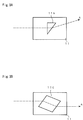
- the light-light deflector 8 will be described in detail below with reference to Fig. 2.
- the light-light deflector 8 comprises a quadrangular-prism crystal of a nonlinear medium for forming an equivalent prism in a portion irradiated with the pumping light P to deflect the emission light A.
- a mask 11 having a triangular opening 11a is arranged at an end portion of the deflector 8 which is irradiated with the pumping light P, and the other end portion is subjected to the transmission treatment over the entire surface.
- the prism-like refractive index change region 10 having a refractive index different from the remaining portion is formed in the nonlinear medium.
- the refractive index of the refractive index change region 10 is changed according to the intensity of the pumping light P. More specifically, the emission light A is incident on the deflector 8 in a direction perpendicular to the pumping light P, and is switched between a state wherein it goes straight and a state wherein it is deflected, depending on the ON/OFF states of the pumping light P. The emission light A is deflected by the refractive index change region 10. Since the refractive index of the region 10 is changed according to the intensity of the pumping light P, a deflection angle a can be desirably controlled by the intensity of the pumping light P.
- the prism-like refractive index change region 10 is formed using the mask 11 having the triangular opening 11a.
- the opening pattern of the mask 11 can be arbitrarily modified as long as the normals to input and output surfaces 10a and 10b of the emission light A do not coincide with the incident direction of the emission light A.
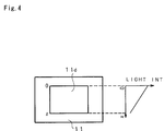
- Fig. 3A shows a modification wherein a right-triangular opening 11b is formed in the mask 11.
- the emission light A is incident on the refractive index change region 10 in a direction perpendicular thereto, and is deflected upward when it emerges from the region 10.
- Fig. 3B shows a modification wherein a parallelogram opening 11c is formed in the mask 11.
- the optical path of the emission light A is shifted in parallel by the refractive index change region 10. Therefore, the emission light A cannot be extracted outside the cavity unless the optical path of the emission light A is largely moved.
- the opening pattern of the mask 11 is not limited to the illustrated ones as long as the input and output surfaces 10a and 10b cross each other.
- the mask 11 having a lens-shaped opening may be used.
- the refractive index can be changed by the outer shape and the like of the mask 11.
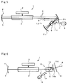
- Fig. 4 shows a modification wherein a filter 11d is arranged on the opening of the mask 11.
- the upper portion of the filter 11d has a high transmittance, and its lower portion has a low transmittance. Therefore, the intensity distribution of the pumping light passing through the filter 11d is as shown in a graph shown on the right side of Fig. 4.
- the upper portion of the quadrangular-prism refractive index change region 10 supplied with strong pumping light has a relatively high refractive index.
- the mask 11 shown in Fig. 4 is equivalent to the mask 11 having the inverse-triangular opening 11a shown in Fig. 2.
- the pulse oscillation of the laser light B can be attained in synchronism with the ON/OFF states of the pumping light P. More specifically, since switching can be optically realized, very high-speed switching characteristics, i.e., switching characteristics having a very small pulse width can be obtained. Furthermore, when the wavelengths and polarization of the pumping light and the emission light, or the axial direction of the light-light deflection member are controlled beforehand to obtain a considerable change in refractive index for light in a direction P in Fig.
- a pulse oscillation laser semiconductor laser
- a large-output, high-speed switching pulse laser a pulse laser having a very small pulse width and large power
- a low-output laser a pulse laser having a very small pulse width and large power
- a pulse laser 1 comprising a so-called cavity damper 12.
- a front mirror 6 comprises a pair of total reflection mirrors 6a and 6b, and these mirrors serve as both reflection and output mirrors.
- the mirror 6b is arranged at an intermediate position between a back mirror 5 and the mirror 6a, and a cavity is constituted by these three mirrors 5, 6a, and 6b.
- the cavity damper 12 is constituted by a light-light deflector 8 interposed between the mirrors 6a and 6b. Emission light A is deflected by the light-light deflector 8 to be extracted from the mirror 6b, as indicated by a broken line in Fig. 5.
- a laser medium 3 is kept excited to reciprocate the emission light A in a laser resonator 4 constituting the cavity so as to maintain a laser oscillation state, thereby increasing internal energy.
- pumping light P for the light-light deflector 8 is set in the ON state to instantaneously form an equivalent prism in the deflector 8, thereby deflecting the emission light A.
- the accumulated energy can be instantaneously extracted.
- pulse laser light B is output.
- the pulse laser light B having a small pulse width and a high peak output can be obtained by the high-speed switching.
- the pulse laser light B can be obtained in synchronism with the ON/OFF states of the pumping light P.
- pulse laser oscillation can be obtained in the OFF state of the pumping light P.
- This embodiment relates to a pulse laser 1 comprising a so-called mode locker 13.
- a front mirror 6 formed of a partial transmission mirror, and the mode locker 13 is constituted by the mirror 6, a light-light deflector 8 inserted between a laser medium 3 and the front mirror 6, and an aperture 14.
- the position of a slit 14a of the aperture 14, and the angle of the front mirror 6 are adjusted to coincide with the deflection angle of the light-light deflector 8, and a cavity is formed between the front mirror 6 and a back mirror 5 in an ON state of pumping light.
- the distance between the front and back mirrors 6 and 5, i.e., the length of a resonator 4 is set to be c/(2 ⁇ f) (where f is the repeating frequency of a pumping source 9).
- the light-light deflector 8 and the aperture 14 constitute a shutter (to be described later), and by utilizing opening/closing operations of the shutter, the phases of a large number of longitudinal modes simultaneously oscillated in the resonator 4 are locked.
- the shutter is opened/closed upon repetition of the ON/OFF states of the pumping light P for the light-light deflector 8.
- the OFF state of the pumping light corresponds to a closed state for stopping light by the aperture 14, and the ON state corresponds to an open state wherein the emission light from a laser medium 3 is deflected, passes through the slit 14a of the aperture 14, and reaches the front mirror 6.
- the pumping source 9 is turned on/off at the repeating frequency f (mode interval), and the shutter is opened/closed in synchronism with one reciprocal movement of the emission light A in the resonator 4, thus performing the same operation as in a case wherein the transmittance is changed in synchronism with one reciprocal movement.
- the emission light A which has passed the slit 14a is subjected to a higher transmittance every time it reciprocates in the resonator 4, and contrary to this, the non-synchronized emission light A is always subjected to a low transmittance.
- the emission light is concentrated on a portion having a high transmittance in association with the gain of the laser medium 3, and is finally output from the front mirror 6.
- pulse laser light B is output.
- the high-speed opening/closing operation of the shutter can be performed in accordance with the ON/OFF states of the pumping light P, and the pulse laser light B having an extremely small pulse width and large peak power can be output.
- the front and back mirrors 6 and 5 may be arranged parallel to each other, and the slit 14a of the aperture 14 may be arranged at a position of the resonator, where central light components pass.
- the opening state of the shutter can be defined by the OFF state of the pumping light P.
- the aperture 14 may be omitted to perform the same operation as described above.
- Fig. 7 shows a modification of the light-light deflector 8 in the above-mentioned three embodiments.
- the laser medium 3 itself comprises an optical crystal of a nonlinear medium which performs light-light deflection by external pumping light P, and the laser medium 3 and the light-light deflector 8 are integrally constituted.
- the pulse laser 1 can be rendered compact, and optical axis alignment can be facilitated.
Landscapes
- Physics & Mathematics (AREA)
- Electromagnetism (AREA)
- Engineering & Computer Science (AREA)
- Plasma & Fusion (AREA)
- Optics & Photonics (AREA)
- Nonlinear Science (AREA)
- Lasers (AREA)
Applications Claiming Priority (2)
| Application Number | Priority Date | Filing Date | Title |
|---|---|---|---|
| JP2200970A JPH0485979A (ja) | 1990-07-27 | 1990-07-27 | パルスレーザ装置 |
| JP200970/90 | 1990-07-27 |
Publications (3)
| Publication Number | Publication Date |
|---|---|
| EP0468795A2 true EP0468795A2 (de) | 1992-01-29 |
| EP0468795A3 EP0468795A3 (en) | 1992-09-16 |
| EP0468795B1 EP0468795B1 (de) | 1995-04-12 |
Family
ID=16433351
Family Applications (1)
| Application Number | Title | Priority Date | Filing Date |
|---|---|---|---|
| EP91306803A Expired - Lifetime EP0468795B1 (de) | 1990-07-27 | 1991-07-25 | Gepulster Laser |
Country Status (4)
| Country | Link |
|---|---|
| US (1) | US5220579A (de) |
| EP (1) | EP0468795B1 (de) |
| JP (1) | JPH0485979A (de) |
| DE (1) | DE69108810T2 (de) |
Families Citing this family (4)
| Publication number | Priority date | Publication date | Assignee | Title |
|---|---|---|---|---|
| US5408480A (en) * | 1993-07-15 | 1995-04-18 | The United States Of America As Represented By The Administrator Of The National Aeronautics And Space Administration | Laser with optically driven Q-switch |
| JP5964779B2 (ja) * | 2013-04-22 | 2016-08-03 | 日本電信電話株式会社 | テラヘルツ波発生装置及びテラヘルツ波発生方法 |
| US9181692B1 (en) | 2014-07-02 | 2015-11-10 | Overly Manufacturing Co. | Covering system for a building substrate |
| CN108275429A (zh) * | 2018-01-17 | 2018-07-13 | 山东钢铁集团日照有限公司 | 一种组合式跑偏开关立柱 |
Family Cites Families (5)
| Publication number | Priority date | Publication date | Assignee | Title |
|---|---|---|---|---|
| US3395961A (en) * | 1964-10-28 | 1968-08-06 | Honeywell Inc | Light deflector |
| FR2506530A1 (fr) * | 1981-05-22 | 1982-11-26 | Thomson Csf | Source coherente de rayonnement generant un faisceau de direction de propagation reglable |
| US4585301A (en) * | 1985-04-23 | 1986-04-29 | Utah State Universtiy Foundation | Optically actuated optical switch apparatus and methods |
| US4825442A (en) * | 1988-04-19 | 1989-04-25 | U.S. Government As Represented By Director, National Security Agency | Planar optical logic |
| US5048051A (en) * | 1990-03-02 | 1991-09-10 | Massachusetts Institute Of Technology | Optically-stabilized plano-plano optical resonators |
-
1990
- 1990-07-27 JP JP2200970A patent/JPH0485979A/ja active Pending
-
1991
- 1991-07-25 EP EP91306803A patent/EP0468795B1/de not_active Expired - Lifetime
- 1991-07-25 US US07/735,647 patent/US5220579A/en not_active Expired - Lifetime
- 1991-07-25 DE DE69108810T patent/DE69108810T2/de not_active Expired - Fee Related
Also Published As
| Publication number | Publication date |
|---|---|
| DE69108810D1 (de) | 1995-05-18 |
| EP0468795A3 (en) | 1992-09-16 |
| EP0468795B1 (de) | 1995-04-12 |
| DE69108810T2 (de) | 1995-09-07 |
| US5220579A (en) | 1993-06-15 |
| JPH0485979A (ja) | 1992-03-18 |
Similar Documents
| Publication | Publication Date | Title |
|---|---|---|
| US5025446A (en) | Intra-cavity beam relay for optical harmonic generation | |
| US5446749A (en) | Diode pumped, multi axial mode, intracavity doubled laser | |
| JP3421184B2 (ja) | 波長可変レーザーにおける波長選択方法および波長可変レーザーにおける波長選択可能なレーザー発振装置 | |
| US3339151A (en) | Beam deflecting lasers | |
| AU6429090A (en) | Coupled-cavity q-switched laser | |
| US20120250706A1 (en) | Transverse laser mode switching | |
| JP5657139B2 (ja) | Co2レーザ装置およびco2レーザ加工装置 | |
| CN101554683A (zh) | 激光振荡器和激光加工设备 | |
| EP0805532B1 (de) | Optischer parametrischer Oszillator | |
| KR100451115B1 (ko) | 파장가변레이저에서의파장선택가능레이저오실레이터 | |
| EP0468795B1 (de) | Gepulster Laser | |
| US3992681A (en) | Method and means for controlling population inversion and electronically scanning solid state laser output deflections | |
| KR100451116B1 (ko) | 파장가변레이저에서의파장선택가능레이저오실레이터 | |
| WO2009130894A1 (ja) | パルスファイバレーザ光源、波長変換レーザ光源、2次元画像表示装置、液晶表示装置、レーザ加工装置及びファイバ付レーザ光源 | |
| US5173916A (en) | Optically pulsed laser having coupled adjoint beams | |
| JP3646465B2 (ja) | レーザ光発生装置 | |
| US5173907A (en) | Modelocked high power laser having an adjoint feedback beam | |
| US20090219955A1 (en) | Laser oscillation method, laser, laser processing method and laser measurement method | |
| JPH07131102A (ja) | Qスイッチレーザ発振装置 | |
| KR20100032055A (ko) | 광매개 공진기 | |
| JPH0643514A (ja) | 波長変換レーザ装置および波長変換レーザプロセシング装置 | |
| JP2006324601A (ja) | レーザ装置及びレーザ加工装置 | |
| RU2095899C1 (ru) | Лазерное устройство одномодового излучения | |
| JPH118430A (ja) | レーザ装置および投影露光装置、並びにパルスレーザ発振方法 | |
| JPH0330380A (ja) | 固体レーザ発振器 |
Legal Events
| Date | Code | Title | Description |
|---|---|---|---|
| PUAI | Public reference made under article 153(3) epc to a published international application that has entered the european phase |
Free format text: ORIGINAL CODE: 0009012 |
|
| AK | Designated contracting states |
Kind code of ref document: A2 Designated state(s): DE FR GB |
|
| PUAL | Search report despatched |
Free format text: ORIGINAL CODE: 0009013 |
|
| AK | Designated contracting states |
Kind code of ref document: A3 Designated state(s): DE FR GB |
|
| 17P | Request for examination filed |
Effective date: 19921102 |
|
| 17Q | First examination report despatched |
Effective date: 19930817 |
|
| GRAA | (expected) grant |
Free format text: ORIGINAL CODE: 0009210 |
|
| AK | Designated contracting states |
Kind code of ref document: B1 Designated state(s): DE FR GB |
|
| ET | Fr: translation filed | ||
| REF | Corresponds to: |
Ref document number: 69108810 Country of ref document: DE Date of ref document: 19950518 |
|
| PLBE | No opposition filed within time limit |
Free format text: ORIGINAL CODE: 0009261 |
|
| STAA | Information on the status of an ep patent application or granted ep patent |
Free format text: STATUS: NO OPPOSITION FILED WITHIN TIME LIMIT |
|
| 26N | No opposition filed | ||
| PGFP | Annual fee paid to national office [announced via postgrant information from national office to epo] |
Ref country code: DE Payment date: 19990723 Year of fee payment: 9 |
|
| PG25 | Lapsed in a contracting state [announced via postgrant information from national office to epo] |
Ref country code: DE Free format text: LAPSE BECAUSE OF NON-PAYMENT OF DUE FEES Effective date: 20010501 |
|
| REG | Reference to a national code |
Ref country code: GB Ref legal event code: IF02 |
|
| PGFP | Annual fee paid to national office [announced via postgrant information from national office to epo] |
Ref country code: FR Payment date: 20050708 Year of fee payment: 15 |
|
| PGFP | Annual fee paid to national office [announced via postgrant information from national office to epo] |
Ref country code: GB Payment date: 20050720 Year of fee payment: 15 |
|
| PG25 | Lapsed in a contracting state [announced via postgrant information from national office to epo] |
Ref country code: GB Free format text: LAPSE BECAUSE OF NON-PAYMENT OF DUE FEES Effective date: 20060725 |
|
| GBPC | Gb: european patent ceased through non-payment of renewal fee |
Effective date: 20060725 |
|
| REG | Reference to a national code |
Ref country code: FR Ref legal event code: ST Effective date: 20070330 |
|
| PG25 | Lapsed in a contracting state [announced via postgrant information from national office to epo] |
Ref country code: FR Free format text: LAPSE BECAUSE OF NON-PAYMENT OF DUE FEES Effective date: 20060731 |