EP0468851A1 - Coussin gonflable et dégonflable et vérin d'extension muni d'un tel coussin - Google Patents
Coussin gonflable et dégonflable et vérin d'extension muni d'un tel coussin Download PDFInfo
- Publication number
- EP0468851A1 EP0468851A1 EP91401968A EP91401968A EP0468851A1 EP 0468851 A1 EP0468851 A1 EP 0468851A1 EP 91401968 A EP91401968 A EP 91401968A EP 91401968 A EP91401968 A EP 91401968A EP 0468851 A1 EP0468851 A1 EP 0468851A1
- Authority
- EP
- European Patent Office
- Prior art keywords
- cushion
- block
- internal slot
- elastically deformable
- inflatable
- Prior art date
- Legal status (The legal status is an assumption and is not a legal conclusion. Google has not performed a legal analysis and makes no representation as to the accuracy of the status listed.)
- Withdrawn
Links
Images


Classifications
-
- B—PERFORMING OPERATIONS; TRANSPORTING
- B25—HAND TOOLS; PORTABLE POWER-DRIVEN TOOLS; MANIPULATORS
- B25B—TOOLS OR BENCH DEVICES NOT OTHERWISE PROVIDED FOR, FOR FASTENING, CONNECTING, DISENGAGING, OR HOLDING
- B25B5/00—Clamps
- B25B5/06—Arrangements for positively actuating jaws
- B25B5/061—Arrangements for positively actuating jaws with fluid drive
- B25B5/065—Arrangements for positively actuating jaws with fluid drive involving the use of flexible pressure bags or diaphragms
-
- B—PERFORMING OPERATIONS; TRANSPORTING
- B25—HAND TOOLS; PORTABLE POWER-DRIVEN TOOLS; MANIPULATORS
- B25B—TOOLS OR BENCH DEVICES NOT OTHERWISE PROVIDED FOR, FOR FASTENING, CONNECTING, DISENGAGING, OR HOLDING
- B25B29/00—Accessories
- B25B29/02—Bolt tensioners
-
- F—MECHANICAL ENGINEERING; LIGHTING; HEATING; WEAPONS; BLASTING
- F15—FLUID-PRESSURE ACTUATORS; HYDRAULICS OR PNEUMATICS IN GENERAL
- F15B—SYSTEMS ACTING BY MEANS OF FLUIDS IN GENERAL; FLUID-PRESSURE ACTUATORS, e.g. SERVOMOTORS; DETAILS OF FLUID-PRESSURE SYSTEMS, NOT OTHERWISE PROVIDED FOR
- F15B15/00—Fluid-actuated devices for displacing a member from one position to another; Gearing associated therewith
- F15B15/08—Characterised by the construction of the motor unit
- F15B15/10—Characterised by the construction of the motor unit the motor being of diaphragm type
Definitions
- the present invention relates to an inflatable and deflatable cushion and an extension cylinder provided with such a cushion.
- the cover is fixed to the tank by connecting elements, such as for example studs, which are screwed into threads provided in the upper part of said tank and which penetrate through through bores provided in the flange of the cover and corresponding to said threads.
- These studs are generally used in fairly large numbers and relatively close to each other, so that the disassembly and reassembly of the cover requires the positioning, screwing and unscrewing of all these studs.
- a tension device is exerted on the studs in order to put them in a pre-stressed state.
- This device is composed of several inflatable membranes superimposed and arranged above the elements to be stretched.
- the membranes are mounted in a support forming an envelope.
- a tensioning device for tightening bolts in which an expandable waterproof member is used composed of a layer of rubber rolled on a metal template.
- the fluid under pressure forces the elastic layer to expand so as to exert a piston action on the element to be stretched.
- a bolt tightening device comprising a cylinder ring with a torus deformable by fluid under pressure.
- the inflatable and deflatable cushions used up to now, in particular in devices for tensioning a connecting element consist of at least one hollow envelope providing, in the deflated state, a chamber internal inflation.
- the developed force is limited taking into account the resistance of the envelope so that to obtain a sufficient force, it is necessary either to increase the active section which is not always possible taking into account the environment and the space available, or superimpose several cushions which complicates the assembly and the pressurized fluid supply system.
- the object of the present invention is to avoid these drawbacks and to propose an inflatable and deflatable cushion whose use requires no particular means. for its installation, while being able to be used in a very wide pressure range.
- the inflatable and deflatable cushion is characterized in that it is formed by a block of elastically deformable material comprising an internal slot whose walls are joined in the initial state to form a solid section of said block and a channel inflation comprising a first end disposed opposite said internal slot and a second end connected to a source of pressurized fluid.
- the present invention also relates to an extension cylinder of a connecting element comprising a member for clamping a workpiece and, at its upper end, a gripping member forming the body of said cylinder and intended to cooperate with a base resting on said part and comprising a housing for said clamping member, said cylinder comprising means exerting a piston action on said connecting element via said gripping member, characterized in that said means exerting a piston action are formed by an inflatable and deflatable cushion as mentioned above.
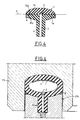
- the inflatable and deflatable cushion 1 according to the invention as shown in FIG. 1 is, in the deflated state, in the form of a block of elastically deformable material such as for example an elastomer or an equivalent material.
- the block has an internal slot 2 and an inflation channel 3 comprising a first end 3a disposed opposite said internal slot 2 and a second end 3b connected to a source of pressurized fluid not shown.
- the walls of the slot 2 are joined so that the cushion 1 has, when deflated, a solid section.
- this elasticity causes a narrowing of the internal slit so that in the initial state, this slit disappears and the inflatable and deflatable cushion is full.
- the cushion according to the present invention does not include any inflation chamber.
- the block is obtained for example by molding, and in this case said channel 3 can be formed by a cylindrical conduit 4, molded directly with said block.
- an insert 5 made of non-stick material is placed in the internal slot 2.
- This insert 5 has the same section and follows the shape of the internal slot 2 so that in the deflated state the walls of said slot are applied to the insert 5 to form an inflatable and deflatable cushion having a solid section.
- the channel 3 is formed in an inflation duct 6, one end of which is attached to a conical bore 7 formed in the block of said cushion 1.
- the inflating and deflatable cushion 1 is formed of two solid parts 1a and 1b each comprising a flat face respectively 10a and 10b opposite a corresponding face of the other part so as to delimit a joint plane "P".
- peripheral portions of the faces 10a and 10b are fixed by any suitable means to each other so as to form between the parts 1a and 1b of the cushion 1 the internal slot 2.
- the walls of the slot 2 are contiguous so that the cushion 1 has, when it is deflated, a solid section, comprising no inflation chamber.
- An insert 5 made of non-stick material can be placed in this internal slot 2.
- the channel 3 can be formed in a duct molded directly with the corresponding part 1a or 1b or in a duct, one end of which is attached in a conical bore formed in said corresponding part.
- the inflatable and deflatable cushion 1 made of elastically deformable material has any shape and section such as for example lenticular and may comprise on its lateral edges at least one rigid segment 9 for example metallic and of triangular shape added or embedded in the material constituting the block of the cushion so as to obstruct the extrusion of said material under pressure, as will be seen later.
- the pressurized fluid arrives through the channel 3 in the internal slot 2 in such a way that the walls of said internal slot move apart to form a chamber.
- the inflatable and deflatable cushion 1 according to the present invention is autoclave, that is to say that the higher the pressure the more the seal is total which makes it possible to increase the reliability and to eliminate the sealing problems.
- this inflatable and deflatable cushion can be, by design, used in a very wide pressure range which can reach values of the order of 3000 bars.
- This jack designated as a whole by the reference 20 allows the tensioning of a connecting element constituted for example by a stud 30.
- the stud 30 is intended for fixing a cover 31 on a tank 32 for example of a nuclear reactor.
- the tank 32 comprises in the upper part, a set of threads 33 distributed symmetrically on a circumference with respect to the main axis of the said tank and intended to each receive the end of a stud 30.
- the cover 31 is provided with a peripheral flange 31a pierced with through bores 34 corresponding to the threads 33 of the tank 32 and distributed symmetrically on a circumference concentric with respect to the main axis of said cover.
- Each through bore 34 is intended for the passage of a stud 30.
- a gripping member 35 On the filtered upper end of the stud 30 is screwed a gripping member 35, constituted for example by a nut, coming to bear on the upper face of the flange 31a for fixing the cover 31 to the tank 32.
- the jack 20 consists of a base 21 resting on the upper face of the flange 31a of the cover 31 and provided with a housing 21a to allow the tightening member 35 to be screwed in or unscrewed by a suitable means, not shown, optionally by means of a pin which can be introduced into the orifices 35a of the clamping member 35.
- This base 21 is surmounted by a tubular part 21b provided at its upper end with a housing 21c.
- This housing 21c is intended to receive the inflatable and deflatable cushion 1 and, for this purpose, has a shape complementary to the half-section of said cushion.
- the base 21 comprises a conduit 22 into which the inflation tube of the cushion 1 penetrates so as to put in communication a source of pressurized fluid, not shown, and the internal slot 2 of said cushion.
- the cushion 1 is also placed in a housing 25a of a shape complementary to the half-section of said cushion, formed in the lower part of a gripping member 25 screwed onto the threaded upper end of the stud 30.
- the upper end of the tubular part 21b of the base 21 enters an annular recess 25b formed in the lower part of the gripper 25 and of slightly larger dimensions to the radial size of the airbag 1 so that its installation is carried out without risk of snagging or jamming.
- the inflatable and deflatable cushion 1 has a toric shape with a lenticular section which makes it possible to reduce the stresses in the parts in contact.
- this insert has, in this case, the shape of a washer.
- the size of the cushion 1 does not exceed the diameter of the gripping member.
- the pressurized fluid emerges, via the conduits 22 and 3, at the level of the internal slot 2 formed in the cushion 1, which causes the walls of said slot to separate (Fig. 6) .
- the segments 9 obstruct the extrusion of the material under pressure.
- the tensioning of the stud 30 thus produced can be followed by the various screwing or unscrewing operations of the clamping member 35.
- the extension cylinder according to the invention is composed of a minimum of elements so that its use does not require any particular means for its installation.
Landscapes
- Engineering & Computer Science (AREA)
- Mechanical Engineering (AREA)
- Physics & Mathematics (AREA)
- Fluid Mechanics (AREA)
- General Engineering & Computer Science (AREA)
- Actuator (AREA)
- Pit Excavations, Shoring, Fill Or Stabilisation Of Slopes (AREA)
- Vibration Dampers (AREA)
- Pressure Vessels And Lids Thereof (AREA)
- Medicines That Contain Protein Lipid Enzymes And Other Medicines (AREA)
- Manipulator (AREA)
Applications Claiming Priority (2)
| Application Number | Priority Date | Filing Date | Title |
|---|---|---|---|
| FR9009513 | 1990-07-25 | ||
| FR9009513A FR2665235B1 (fr) | 1990-07-25 | 1990-07-25 | Coussin gonflable et verin d'extension muni d'un tel coussin. |
Publications (1)
| Publication Number | Publication Date |
|---|---|
| EP0468851A1 true EP0468851A1 (fr) | 1992-01-29 |
Family
ID=9399093
Family Applications (1)
| Application Number | Title | Priority Date | Filing Date |
|---|---|---|---|
| EP91401968A Withdrawn EP0468851A1 (fr) | 1990-07-25 | 1991-07-15 | Coussin gonflable et dégonflable et vérin d'extension muni d'un tel coussin |
Country Status (12)
| Country | Link |
|---|---|
| EP (1) | EP0468851A1 (cs) |
| JP (1) | JPH04290681A (cs) |
| KR (1) | KR920002275A (cs) |
| CN (1) | CN1058461A (cs) |
| AU (1) | AU8049091A (cs) |
| CA (1) | CA2047808A1 (cs) |
| CS (1) | CS230791A3 (cs) |
| FI (1) | FI913548A7 (cs) |
| FR (1) | FR2665235B1 (cs) |
| NO (1) | NO912871L (cs) |
| RU (1) | RU2046225C1 (cs) |
| ZA (1) | ZA915799B (cs) |
Cited By (2)
| Publication number | Priority date | Publication date | Assignee | Title |
|---|---|---|---|---|
| WO2002018103A1 (en) * | 2000-08-28 | 2002-03-07 | John Paul Mckelvey | Inflatable tensioning device |
| WO2006024833A1 (en) * | 2004-09-03 | 2006-03-09 | Tentec Limited | Fastening apparatus |
Families Citing this family (4)
| Publication number | Priority date | Publication date | Assignee | Title |
|---|---|---|---|---|
| RU2204061C2 (ru) * | 1999-08-27 | 2003-05-10 | Марти Александр Николаевич | Торовая механическая мышца |
| CN102117665B (zh) * | 2009-12-31 | 2013-01-02 | 中国核动力研究设计院 | 反应堆压力容器主螺栓孔密封塞的操作工具 |
| DE202010011337U1 (de) * | 2010-08-12 | 2010-10-21 | Bohnet, Hans | System zur Abdichtung eines Rohrleitungssystems |
| JP5854220B2 (ja) * | 2012-01-27 | 2016-02-09 | Smc株式会社 | 電動クランプ装置 |
Citations (5)
| Publication number | Priority date | Publication date | Assignee | Title |
|---|---|---|---|---|
| US2815966A (en) * | 1951-06-04 | 1957-12-10 | Nat Clay Pipe Manufacturers In | Pipe joint and inflatable gasket therefor |
| FR1457173A (fr) * | 1965-01-27 | 1966-10-28 | Charmilles Sa Ateliers | Dispositif d'étanchéité entre deux organes |
| FR2307200A1 (fr) * | 1975-04-11 | 1976-11-05 | Noel Jean Louis | Dispositif d'obturation avec etancheite d'une ouverture par un panneau |
| US4342336A (en) * | 1979-10-03 | 1982-08-03 | Satterthwaite J Glenn | Double-acting inflatable seal |
| FR2580742A1 (fr) * | 1985-04-18 | 1986-10-24 | Sealol | Procede et dispositif de serrage de boulonnerie |
-
1990
- 1990-07-25 FR FR9009513A patent/FR2665235B1/fr not_active Expired - Fee Related
-
1991
- 1991-07-15 EP EP91401968A patent/EP0468851A1/fr not_active Withdrawn
- 1991-07-17 AU AU80490/91A patent/AU8049091A/en not_active Abandoned
- 1991-07-23 NO NO91912871A patent/NO912871L/no unknown
- 1991-07-23 CS CS912307A patent/CS230791A3/cs unknown
- 1991-07-24 KR KR1019910012653A patent/KR920002275A/ko not_active Withdrawn
- 1991-07-24 RU SU915001189A patent/RU2046225C1/ru active
- 1991-07-24 FI FI913548A patent/FI913548A7/fi not_active Application Discontinuation
- 1991-07-24 CA CA002047808A patent/CA2047808A1/fr not_active Abandoned
- 1991-07-24 ZA ZA915799A patent/ZA915799B/xx unknown
- 1991-07-24 CN CN91105083A patent/CN1058461A/zh active Pending
- 1991-07-25 JP JP3208510A patent/JPH04290681A/ja not_active Withdrawn
Patent Citations (5)
| Publication number | Priority date | Publication date | Assignee | Title |
|---|---|---|---|---|
| US2815966A (en) * | 1951-06-04 | 1957-12-10 | Nat Clay Pipe Manufacturers In | Pipe joint and inflatable gasket therefor |
| FR1457173A (fr) * | 1965-01-27 | 1966-10-28 | Charmilles Sa Ateliers | Dispositif d'étanchéité entre deux organes |
| FR2307200A1 (fr) * | 1975-04-11 | 1976-11-05 | Noel Jean Louis | Dispositif d'obturation avec etancheite d'une ouverture par un panneau |
| US4342336A (en) * | 1979-10-03 | 1982-08-03 | Satterthwaite J Glenn | Double-acting inflatable seal |
| FR2580742A1 (fr) * | 1985-04-18 | 1986-10-24 | Sealol | Procede et dispositif de serrage de boulonnerie |
Cited By (3)
| Publication number | Priority date | Publication date | Assignee | Title |
|---|---|---|---|---|
| WO2002018103A1 (en) * | 2000-08-28 | 2002-03-07 | John Paul Mckelvey | Inflatable tensioning device |
| US6813955B2 (en) | 2000-08-28 | 2004-11-09 | Mckelvey John Paul | Inflatable tensioning device |
| WO2006024833A1 (en) * | 2004-09-03 | 2006-03-09 | Tentec Limited | Fastening apparatus |
Also Published As
| Publication number | Publication date |
|---|---|
| FI913548L (fi) | 1992-01-26 |
| CS230791A3 (en) | 1992-02-19 |
| FR2665235B1 (fr) | 1993-12-03 |
| AU8049091A (en) | 1992-01-30 |
| RU2046225C1 (ru) | 1995-10-20 |
| CN1058461A (zh) | 1992-02-05 |
| ZA915799B (en) | 1993-03-31 |
| NO912871L (no) | 1992-01-27 |
| KR920002275A (ko) | 1992-02-28 |
| FI913548A7 (fi) | 1992-01-26 |
| FI913548A0 (fi) | 1991-07-24 |
| NO912871D0 (no) | 1991-07-23 |
| FR2665235A1 (fr) | 1992-01-31 |
| JPH04290681A (ja) | 1992-10-15 |
| CA2047808A1 (fr) | 1992-01-26 |
Similar Documents
| Publication | Publication Date | Title |
|---|---|---|
| EP0096645B1 (fr) | Dispositif d'étanchéité pour robinet à tournant sphérique | |
| FR2484049A1 (fr) | Dispositif d'accouplement comportant des parties male et femelle associees a des elements de blocage interdisant leur separation | |
| FR2493467A1 (fr) | Dispositif de raccordement hydraulique a accouplement rapide | |
| EP1148207A1 (fr) | Dispositif de connexion d'une ligne immergée de transport de fluide | |
| FR2514439A1 (fr) | Rotule pour pied de colonne montante | |
| FR2533641A1 (fr) | Perfectionnements aux reservoirs de pression a prix de revient reduit | |
| FR2781274A1 (fr) | Raccord pour tubes, comprenant un troncon de raccordement conforme a une extremite d'un tube | |
| FR2571459A3 (fr) | Ressort pneumatique comprenant deux elements relies par une membrane flexible impermeable aux gaz | |
| FR2665235A1 (fr) | Coussin gonflable et verin d'extension muni d'un tel coussin. | |
| EP0222625B2 (fr) | Dispositif de tension pour le serrage et le desserrage de boulons ou goujons | |
| FR2488662A1 (fr) | Dispositif reservoir de pression, notamment accumulateur de pression a vessie remplacable | |
| FR2544828A1 (fr) | Dispositif d'etancheite pour tube d'etambot | |
| EP2309164B1 (fr) | Dispositif de raccordement instantané ayant des zones de guidage et d'étanchéité inversées | |
| FR2562958A1 (fr) | Pompe a membrane a piston | |
| FR2544432A1 (fr) | Verin parasismique pour structure elastiquement appuyee | |
| EP0198733A1 (fr) | Dispositif de suspension hydroélastique pour plates-formes mobiles de forage auto-élévatrices | |
| EP0257455A1 (fr) | Tête d'obturation pour banc d'épreuve hydraulique de tubes | |
| FR2504974A1 (fr) | Valve hydraulique de coulissement pour verin de mine | |
| WO2023187212A1 (fr) | Tête de connexion rapportable sur une ouverture d'un élément de tuyauterie à bride pour son contrôle sous pression | |
| FR2681931A1 (fr) | Raccord a soupape, en particulier raccord de mesure pour circuits de fluide sous hautes tensions. | |
| FR2518698A1 (fr) | Raccord a deconnection rapide | |
| FR2790056A1 (fr) | Dispositif de connexion pour le raccordement d'une extremite de conduite a un organe | |
| FR2504993A1 (fr) | Reservoir de pression reparable | |
| CA1297923C (fr) | Raccord tournant et etanche pour fluide sous pression | |
| EP0350394B1 (fr) | Système d'évacuation d'eaux pluviales |
Legal Events
| Date | Code | Title | Description |
|---|---|---|---|
| PUAI | Public reference made under article 153(3) epc to a published international application that has entered the european phase |
Free format text: ORIGINAL CODE: 0009012 |
|
| 17P | Request for examination filed |
Effective date: 19911206 |
|
| AK | Designated contracting states |
Kind code of ref document: A1 Designated state(s): BE CH DE ES GB IT LI NL SE |
|
| 17Q | First examination report despatched |
Effective date: 19940208 |
|
| STAA | Information on the status of an ep patent application or granted ep patent |
Free format text: STATUS: THE APPLICATION HAS BEEN WITHDRAWN |
|
| 18W | Application withdrawn |
Withdrawal date: 19941219 |