EP0468887B1 - Struktur zur Absorption von elektromagnetischen Wellen in Breitband-Hochfrequenz - Google Patents
Struktur zur Absorption von elektromagnetischen Wellen in Breitband-Hochfrequenz Download PDFInfo
- Publication number
- EP0468887B1 EP0468887B1 EP19910402059 EP91402059A EP0468887B1 EP 0468887 B1 EP0468887 B1 EP 0468887B1 EP 19910402059 EP19910402059 EP 19910402059 EP 91402059 A EP91402059 A EP 91402059A EP 0468887 B1 EP0468887 B1 EP 0468887B1
- Authority
- EP
- European Patent Office
- Prior art keywords
- magnetic
- composite
- absorber
- permittivity
- dielectric
- Prior art date
- Legal status (The legal status is an assumption and is not a legal conclusion. Google has not performed a legal analysis and makes no representation as to the accuracy of the status listed.)
- Expired - Lifetime
Links
- 238000010521 absorption reaction Methods 0.000 title claims description 10
- 229910000859 α-Fe Inorganic materials 0.000 claims description 102
- 239000002131 composite material Substances 0.000 claims description 72
- 239000000463 material Substances 0.000 claims description 58
- 239000006096 absorbing agent Substances 0.000 claims description 50
- 230000005291 magnetic effect Effects 0.000 claims description 43
- 239000006185 dispersion Substances 0.000 claims description 39
- 238000001228 spectrum Methods 0.000 claims description 28
- 230000035699 permeability Effects 0.000 claims description 23
- 238000002310 reflectometry Methods 0.000 claims description 23
- 239000011230 binding agent Substances 0.000 claims description 18
- 238000000034 method Methods 0.000 claims description 11
- 230000007423 decrease Effects 0.000 claims description 10
- 239000011159 matrix material Substances 0.000 claims description 8
- 239000008187 granular material Substances 0.000 claims description 7
- 239000000696 magnetic material Substances 0.000 claims description 7
- 230000005293 ferrimagnetic effect Effects 0.000 claims description 6
- 239000000203 mixture Substances 0.000 claims description 6
- 238000002156 mixing Methods 0.000 claims description 5
- 230000005294 ferromagnetic effect Effects 0.000 claims description 4
- 238000005245 sintering Methods 0.000 claims description 4
- 239000011324 bead Substances 0.000 claims description 3
- 239000003989 dielectric material Substances 0.000 claims description 3
- 238000012360 testing method Methods 0.000 claims description 3
- 230000010287 polarization Effects 0.000 claims description 2
- 230000009467 reduction Effects 0.000 claims description 2
- 239000000126 substance Substances 0.000 claims description 2
- 230000001902 propagating effect Effects 0.000 claims 2
- 230000005684 electric field Effects 0.000 claims 1
- 230000000694 effects Effects 0.000 description 16
- 238000013461 design Methods 0.000 description 15
- XEEYBQQBJWHFJM-UHFFFAOYSA-N Iron Chemical compound [Fe] XEEYBQQBJWHFJM-UHFFFAOYSA-N 0.000 description 14
- 239000000843 powder Substances 0.000 description 13
- 229910018605 Ni—Zn Inorganic materials 0.000 description 8
- 230000005415 magnetization Effects 0.000 description 6
- 239000000758 substrate Substances 0.000 description 6
- 229910052742 iron Inorganic materials 0.000 description 5
- 230000008569 process Effects 0.000 description 5
- 206010022979 Iron excess Diseases 0.000 description 4
- 238000013459 approach Methods 0.000 description 4
- 239000011521 glass Substances 0.000 description 4
- 238000004519 manufacturing process Methods 0.000 description 4
- 230000004888 barrier function Effects 0.000 description 3
- 238000004364 calculation method Methods 0.000 description 3
- 230000008859 change Effects 0.000 description 3
- 150000001875 compounds Chemical class 0.000 description 3
- 238000001033 granulometry Methods 0.000 description 3
- 238000004088 simulation Methods 0.000 description 3
- 229910052725 zinc Inorganic materials 0.000 description 3
- 239000002202 Polyethylene glycol Substances 0.000 description 2
- VYPSYNLAJGMNEJ-UHFFFAOYSA-N Silicium dioxide Chemical compound O=[Si]=O VYPSYNLAJGMNEJ-UHFFFAOYSA-N 0.000 description 2
- GWEVSGVZZGPLCZ-UHFFFAOYSA-N Titan oxide Chemical compound O=[Ti]=O GWEVSGVZZGPLCZ-UHFFFAOYSA-N 0.000 description 2
- 229910007564 Zn—Co Inorganic materials 0.000 description 2
- 239000013590 bulk material Substances 0.000 description 2
- 230000002950 deficient Effects 0.000 description 2
- 239000002902 ferrimagnetic material Substances 0.000 description 2
- 239000003302 ferromagnetic material Substances 0.000 description 2
- 238000010304 firing Methods 0.000 description 2
- 230000004927 fusion Effects 0.000 description 2
- 150000002505 iron Chemical class 0.000 description 2
- JEIPFZHSYJVQDO-UHFFFAOYSA-N iron(III) oxide Inorganic materials O=[Fe]O[Fe]=O JEIPFZHSYJVQDO-UHFFFAOYSA-N 0.000 description 2
- VNWKTOKETHGBQD-UHFFFAOYSA-N methane Chemical compound C VNWKTOKETHGBQD-UHFFFAOYSA-N 0.000 description 2
- 238000005457 optimization Methods 0.000 description 2
- 229920001223 polyethylene glycol Polymers 0.000 description 2
- 238000001556 precipitation Methods 0.000 description 2
- 238000012545 processing Methods 0.000 description 2
- 150000003839 salts Chemical class 0.000 description 2
- 229920001342 Bakelite® Polymers 0.000 description 1
- VEXZGXHMUGYJMC-UHFFFAOYSA-M Chloride anion Chemical compound [Cl-] VEXZGXHMUGYJMC-UHFFFAOYSA-M 0.000 description 1
- 229910017518 Cu Zn Inorganic materials 0.000 description 1
- 229910017752 Cu-Zn Inorganic materials 0.000 description 1
- 229910017943 Cu—Zn Inorganic materials 0.000 description 1
- 239000004593 Epoxy Substances 0.000 description 1
- 206010022971 Iron Deficiencies Diseases 0.000 description 1
- 229910008405 Li-Zn Inorganic materials 0.000 description 1
- 229910007049 Li—Zn Inorganic materials 0.000 description 1
- 239000004642 Polyimide Substances 0.000 description 1
- 239000004809 Teflon Substances 0.000 description 1
- 229920006362 Teflon® Polymers 0.000 description 1
- 241000656145 Thyrsites atun Species 0.000 description 1
- 230000006978 adaptation Effects 0.000 description 1
- 238000004458 analytical method Methods 0.000 description 1
- 239000004637 bakelite Substances 0.000 description 1
- DSAJWYNOEDNPEQ-UHFFFAOYSA-N barium atom Chemical group [Ba] DSAJWYNOEDNPEQ-UHFFFAOYSA-N 0.000 description 1
- 230000008901 benefit Effects 0.000 description 1
- WMWLMWRWZQELOS-UHFFFAOYSA-N bismuth(III) oxide Inorganic materials O=[Bi]O[Bi]=O WMWLMWRWZQELOS-UHFFFAOYSA-N 0.000 description 1
- 239000000919 ceramic Substances 0.000 description 1
- 239000012707 chemical precursor Substances 0.000 description 1
- 229910052681 coesite Inorganic materials 0.000 description 1
- TVZPLCNGKSPOJA-UHFFFAOYSA-N copper zinc Chemical compound [Cu].[Zn] TVZPLCNGKSPOJA-UHFFFAOYSA-N 0.000 description 1
- 229910052906 cristobalite Inorganic materials 0.000 description 1
- 230000003247 decreasing effect Effects 0.000 description 1
- 230000006735 deficit Effects 0.000 description 1
- 229910003460 diamond Inorganic materials 0.000 description 1
- 239000010432 diamond Substances 0.000 description 1
- 238000009826 distribution Methods 0.000 description 1
- 239000000839 emulsion Substances 0.000 description 1
- 230000002349 favourable effect Effects 0.000 description 1
- 238000009472 formulation Methods 0.000 description 1
- 239000003292 glue Substances 0.000 description 1
- 238000010438 heat treatment Methods 0.000 description 1
- 238000001453 impedance spectrum Methods 0.000 description 1
- 230000006872 improvement Effects 0.000 description 1
- 238000010348 incorporation Methods 0.000 description 1
- 238000009434 installation Methods 0.000 description 1
- 239000011810 insulating material Substances 0.000 description 1
- 230000010354 integration Effects 0.000 description 1
- 230000003993 interaction Effects 0.000 description 1
- 238000009766 low-temperature sintering Methods 0.000 description 1
- 238000002844 melting Methods 0.000 description 1
- 230000008018 melting Effects 0.000 description 1
- 238000012986 modification Methods 0.000 description 1
- 230000004048 modification Effects 0.000 description 1
- 238000005325 percolation Methods 0.000 description 1
- 239000004033 plastic Substances 0.000 description 1
- 229920001721 polyimide Polymers 0.000 description 1
- 229920000642 polymer Polymers 0.000 description 1
- 239000011148 porous material Substances 0.000 description 1
- 239000002243 precursor Substances 0.000 description 1
- 230000000750 progressive effect Effects 0.000 description 1
- 238000000197 pyrolysis Methods 0.000 description 1
- 229920005989 resin Polymers 0.000 description 1
- 239000011347 resin Substances 0.000 description 1
- 238000007493 shaping process Methods 0.000 description 1
- 239000000377 silicon dioxide Substances 0.000 description 1
- 235000012239 silicon dioxide Nutrition 0.000 description 1
- 229910052682 stishovite Inorganic materials 0.000 description 1
- 230000001629 suppression Effects 0.000 description 1
- 229920001169 thermoplastic Polymers 0.000 description 1
- 239000004416 thermosoftening plastic Substances 0.000 description 1
- 230000007704 transition Effects 0.000 description 1
- 229910052905 tridymite Inorganic materials 0.000 description 1
- 239000002966 varnish Substances 0.000 description 1
Images


Classifications
-
- B—PERFORMING OPERATIONS; TRANSPORTING
- B82—NANOTECHNOLOGY
- B82Y—SPECIFIC USES OR APPLICATIONS OF NANOSTRUCTURES; MEASUREMENT OR ANALYSIS OF NANOSTRUCTURES; MANUFACTURE OR TREATMENT OF NANOSTRUCTURES
- B82Y25/00—Nanomagnetism, e.g. magnetoimpedance, anisotropic magnetoresistance, giant magnetoresistance or tunneling magnetoresistance
-
- H—ELECTRICITY
- H01—ELECTRIC ELEMENTS
- H01Q—ANTENNAS, i.e. RADIO AERIALS
- H01Q17/00—Devices for absorbing waves radiated from an antenna; Combinations of such devices with active antenna elements or systems
Definitions
- Both can vary with frequency, i.e. their "spectra” are to be considered ; both can be superposed in the same material, describing so a "dielectro-magnetic" lossy material.
- German Patent 1 014 616 a single adaptation layer with a high refraction index for the reflexion free transition of an electromagnetic ray, from a medium like air in another medium.
- a first aim of the invention is to describe a conductive backed absorber, covering the very wide frequency range of 30 MHz - 1 GHz and higher with reduced electromagnetic reflectivity : indeed, such frequency range corresponds to the range of mandatory performance for ALC testing.
- the related site attenuation or SAD, site attenuation deviation
- a second aim is to describe several unexpected interesting materials / combinations thereof, allowing to achieve the above results.
- a third aim is to describe a related surprising effect that the simulation of such "artificial ferrites” can be made at the macroscopic level, i.e. where an equivalent to the high volume concentrations is achieved by equivalent “gaps" between bulk ferrite tiles, achieving thus the simulation of the desired permeability spectra.
- a fourth aim is related to the presence of non (or low) magnetic intersticial material, inside the composite, (on the microscopic level), or outside the ferrite (on a macroscopic level) :
- the overall effective permittivity can be controlled, and a useful permittivity dispersion introduced, for broadband operation.
- non magnetic intersticial binder material can be thermoplastic or thermosettable, allowing the implementation by a low temperature process, rather than high temperature sintering, with the advantages of easy shaping, dimensioning and global application.
- a fifth aim is to optimize the broad low reflectivity range, by the superposition of several layers of different dielectromagnetica, each optimized for a given frequency band, within the overall frequency range.
- Such layers can use different "artificial ferrites"(various C v′s , various magnetica), and/or different effective airgaps, between tiles, in different layers, simulating the corresponding dispersion spectra.
- a composite dielectromagnetic electromagnetic wave absorber material adapted to reduce electromagnetic wave reflectivity over the 30 MHz to 1 GHz and higher frequency range in which at least one ferro- or ferrimagnetic granular material is surrounded by an essentially non-magnetic matrix binding material, said granular material having an effective volume concentration of 10 to 99,9 %, said absorber showing an imaginary permeability varying as the reciprocal of the frequency over said frequency range, said absorber material being characterized by the combination of:
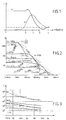
- Figure 1 shows a typical permeability spectrum. Between O and f1, the real part ⁇ ′ is constant, and losses ⁇ ⁇ are small : this is the area of normal use of a ferrimagnetic or ferromagnetic material. Region f1 to f4 corresponds to the dispersion area, where ⁇ ′ decreases, and losses ⁇ ⁇ are maximum : this area is used in this invention.
- concentrations are much higher than those described and used in classical absorptive composites : but one can thus achieve, with a composite, an equivalency of the bulk Ni-Zn etc. ferrites mentioned.
- ⁇ is the gyromagnetic factor
- Ms the saturation magnetization
- f the frequency.
- the product ( ⁇ ′- I).f (in MHz) is approximatively equal to 3500.
- Fig. 3 shows ⁇ ′ and ⁇ ⁇ values for the same composites, with Mn-Zn ferrite of Fig. 2.
- ⁇ ′ have been achieved with the use of high permittivity, good insulating matrix material, where the ferrite grains of the composite are more or less conductive (including carbonyl iron), or with higher resistivity ferrites, with a more or a less conductive matrix material.
- the very principle of composite structure allows the integration of other dielectric relaxation effects (causing the dispersion), of dipolar resonance effects (causing additional dispersion), of dipolar resonances (causing additional absorption), chiral effects (causing additional dispersion and absorption, i.e. the spectra of permittivity, can be controlled as opposed to the built-in permittivity of a bulk ferrite.
- Fig. 2 suggests a concentration C v between 60 and 75 %.
- the calculation, for C v 68 % for example, shows curve B, Fig. 4, for a thickness of 10 mm for this absorber : for 245 MHz, a maximum of reflectivity of approx. 30 dB is achieved.
- Fig. 5 shows how this maximum varies, with the thickness - and too the appearance of a maximum for a 3 ⁇ /4 resonance, as mentioned earlier.
- This example demonstrates the design of composites, where frequency behaviour is modeled according to the concentration C v of ferro-ferrimagnetica in a composite material.
- Multilayer Absorber for the 30-1000 MHz range
- the wave-impedance of the above mentioned composites decreases, when the magnetic concentration C v increases ; whereas the propagation constant increases with C v .
- the overall reflectivity achieved (Fig. 6, wave D), shows a good improvement around 250 MHz, but a decrease of performance towards the upper end of the frequency range.
- a reflectivity of better than 8 dB is achieved over the 30 MHz - 1 GHz frequency range.
- the exact calculation, taking in account interactions between the layers, achieves a better than 10 dB reflectivity, with an overall thickness reduced from 16,5 + 10 + 7,5 34 mm to 25 mm.
- Mn-Zn ferrite iron-excess ferrite composite
- Each layer is calculated to represent the quarter-wavelength at the above spot-frequencies (thicknesses 16,5, 9,5 and 7 mm) : Reflectivity is better than 15 dB over the frequency range, for this non-optimized design.
- Ni-Zn ferrite composite outerlayer with much reduced wave impedance, achieves a reflectivity of better than 20 dB over the frequency range, without optimization (Example 2.3).
- the same Mn-Zn ferrite, with high low frequency permeability has been used to implement three very different composites, with volume concentrations C v of 90,6, 68 and 40 % of the ferrite.
- the third layer (7 mm thickness) has to have relative airgaps of about 0,20, i.e. a spacing of about 2 cm between tiles of 10 x 10 cm size.
- the same reasoning can be applied to bulk ferrite (instead of C v 90,6 % composite).
- the first inside layer has to have a relative spacing of about 0,024, to represent the ⁇ * spectra of the 90,6 % composite. This corresponds to a spacing between 10 cm square tiles of about 2,4 mm.
- This figure shows, on another hand, the fallacy to achieve specified reflectivity data, with adjoined bulk ferrite absorber tiles.
- the very sensivity of high C v (including the bulk ferrite) towards airgaps, can be reduced by spacing lower C V composites as interfacial layer or "glue" between such tiles.
- Variable spacing offers, following the invention, an interesting possibility to change reflectivity spectra, during the installation of the absorbers in ALC chambers, etc... : this feature is interesting to consider, when reflectivity v.s incidence angles has to be optimized, as for "site attenuation" in test sites.
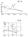
- Fig. 7bis shows the reflectivities for the bulk iron deficit Mn-Zn ferrite of example 2 (curve I), and for the simulated "composite", consisting of the same bulk ferrite, with the airgaps (curve II).
- Ni-Zn and Mg-Zn ferrites can thus be diluted, as well as Ni-Zn-Co, Li-Zn, etc.. ferrites, for even higher frequencies.
- the graph shows that reflexion cancelling can be achieved, down to lower frequencies (i.e. 1 MHz), but that such designs need the implementation of high and precise values of concentration C v , with no quarter-wave design possible with bulk Mn-Zn or Fe-Mn-Zn ferrites.
- Graph 8 shows the wave impedance of several ferrite: composites, of volume concentration C v of 68,5 %.
- Curve I shows the Mn-Zn (with excess iron) ferrite wave impedance of example 1, relative to the free-space impedance:Zm/Zo.
- Curve II shows the relative impedance for the Mn-Zn (with iron deficiency), of example 1, and curve III the wave impedance for the (Ni 0,5 Zn 0,5 ) ferrite of example 2.3.
- reflectivity cancellations can thus be introduced, adding to or independantly from the ⁇ /4 (and3/4 ⁇ ..) cancellations presented.
- thermosettable or other non-flexible binders can be used.
- Classical techniques use polyvinyl-riglycol (PVA) and polyethyleneglycol (PEC), well known for the implementation of "green" materials, in ferrite manufacturing ; these or other matrix materials then disappear more or less during the firing process, and allow the implementation of high controlled values of concentration C v .
- Resintering of already finally sintered ferrite powders is a typical approach to achieve such high concentrations, according to the invention.
- Hot fusion techniques with bakelite powder are known in the process for manufacturing molded magnetic forms.
- Other techniques include epoxy and other resins, polyimide varnishes, emulsions of teflon on vinydilene chloride, polyallylate powder ; furthermore, low temperature sintering can be used with ad-hoc glasses, ferroelectric powders, i.e. substances which fuse at temperature below the ferrite melting temperature.
- the invention includes such dielectrics, and furthermore dielectrics which show a permittivity dispersion, in the considered frequency range : here, the conduction effects of the magnetic grains, the conduction of the binder material and the dielectric behaviour of both,have to be considered, with eventually ferro-electric and barrier-layer effects : such effects can combine and show conductive dispersion, Debye relaxation effects, Maxwell-Wagner interface resonance, and dipolar resonance effects : one of the interesting unexpected results is the presence of dielectric dispersion spectra, similar to those of Fig. 2, for relaxation and resonance effects, i.e. the possibility to model dielectric dispersion, as needed.
- I refer to the ferrites mentioned earlier, presenting a resistivity in the range of 1 ⁇ .m,for the iron excess Mn-Zn ferrite, of 50 ⁇ .m,for the iron deficient ferrite, and 102to 105 ⁇ .m for Mg-Zn and Ni-Zn stocheometric ferrites.
- dielectric loss angles will depend strongly on the presence or absence of percolation, i.e. of the value of C v and the presence of insulating material around each grain.
- the invention considers too, very low resistivity ferrites, which will introduce a strong dielectric dispersion.
- a relatively insulating ferrite is imbedded in a more or less conductive binder, for example, a binder loaded with conductive carbon black, where a very small load is necessary, when C v is high.
- a binder loaded with conductive carbon black where a very small load is necessary, when C v is high.
- permittivity ⁇ ′ varies from 91 to 25, over the 30 MHz to 1 GHz frequency range ; resistivity varies from 1 to 0,1 ⁇ .m approximately.
- the design shows a "quarter-wave" frequency of about 50 MHz, with a thickness of approx. 11 mm.
- the necessary thickness of the new composite layer has been reduced from 16,5 mm to 11 mm and the volume concentration of ferrite from 90,6 % to 68 % - with an additional broading of the low reflectivity frequency range, allowing for a reduced number of layers, in the described multilayers design.
- Such a material is a typical representation of a "synthetic functional compound", in the sense of this invention.
- a low resistivity can be implemented on the surface of the granular material, by thin-layer enduction technique, which are described for example in my french patent N° 8.613. 093.
- barrier layers in the system Sr Ti O3 - Bi2O3 -n.Ti O2, corresponding to the volume of C v desired.
- This dielectric is mixed as a powder (direct or as a precursor) with the ferrite grains .
- the composite is subsequently sintered as low enough tempetatures, so as to avoid modifications of the ferrite.
- the high permittivity powder can be used directly, within a classical polymer or plastic as binder.
- a medium to good conductive ferrite like the Mn-Zn ferrite of Fig. 2 and 3, or the Ni-Zn ferrite described
- such a composite has been implemented, after sintering with a Sr Ti O3 binder, or Sr Ti O3 with a small addition of Bi2 - 2 Ti O2, where the real permittivity varies approximatively from 2000 to 200, from 30 MHz to 1 GHz.
- the corresponding "quarterwavelength" absorber has not only a reduced thickness, but too a very broad range reflectivity, of over 25 dB, from 30 MHz to 3 GHz and higher.
- the modelization ad voluntas of ad hoc dielectromagnetics involves different ferri/ferromagnetic materials, used alone or together, in composites - with a practical range of effective volume concentrations of about 40 to 99,5 % - so as to have, all along, the means to introduce a dielectric factor, independant of the ferrite itself.
- the modelization and implementation of dielectric characteristics makes use of at least two different phases, where one can, so as to achieve the desired results, intervene ad volontas on the intersticial matrix, (without modifying the ferro/ferrimagnetic grains), with low temperature processes, easier to achieve and to control.
- Such structures include applications to electrical lines and wave-guides, shields, filters, and other electromagnetic wave structures and systems.
- composite beads for Common-Mode suppression on wires, cables, ect.
- composites with variable high values of C v can be used, or bulk partioned ferrites (with controlled airgaps), so as to allow frequency optimization.
Landscapes
- Chemical & Material Sciences (AREA)
- Engineering & Computer Science (AREA)
- Nanotechnology (AREA)
- Crystallography & Structural Chemistry (AREA)
- Shielding Devices Or Components To Electric Or Magnetic Fields (AREA)
- Hard Magnetic Materials (AREA)
- Aerials With Secondary Devices (AREA)
- Soft Magnetic Materials (AREA)
Claims (26)
- Ein dielektromagnetisches Absorber-Komposit-Material, für die Dämpfung elektromagnetischer Wellen, in dem 30 MHz bis 1 Ghz (und höher) Frequenzgebiet, in dem wenigstens ein ferro- oder ferrimagnetisches Granularmaterial umgeben ist von einem wenig- oder nicht-magnetischen Bindenmaterial, wo das Granularmaterial eine effektive Volumenkonzentration von 10 bis 99,9% darstellt, wo das Absorbermaterial eine imaginäre Permeabilität aufzeigt, die über das genannte Frequenzbereich sich reziprok der Frequenz ändert, und wo das Absorbermaterial gekennzeichnet ist, durch eine Kombination von :- ausgewählten magnetischen Eigenschaften dieses dielektromagnetischen Materials, so dass das Bereich der magnetischen Dispersion, das heisst, das Frequenzbereich wo die reelle Permeabilität abnimmt mit zunehmender Frequenz und die Verlust-Permeabilität gross oder maximal ist, in dem betroffenen Frequenzbereich, bedingt durch die Volumen-Konzentration in dem Material und/oder durch äussere Luftspalte, das heisst das Einbringen von mikrokopischen wenig oder nicht-magnetischen Spälten und/oder makrokopischen wenig-oder nicht-magnetischen Spälten, und- ausgewählten dielektrischen Eigenshaften dieses dielektromagnetischen Materials, verbunden mit den Eigenschaften der interstiziellen Spälte und/oder des dielektrischen Bindematerials, so dass eine globale hohe dielektrische Permittivität ε erreicht wird, mit gegebenenfalls, einer gewissen dielektrischen Dispersion, das heisst einem Frequenzbereich, wo die komplexe Permittivität gewisse dielektrische Verluste und ein Abnehmen mit steigender Frequenz aufweist, in dem genannten Frequenzbereich.
- Ein Material nach Anspruch 1, wo die Spektra der Permeabilität und Permittivität erhalten werden, durch die Auswahl der Volumen-Konzentration des/der magnetischen Materialien, im Gegensatz von verschiedenen chemischen Kompositionen eines kompakten ferriferromagnetischen Materials.
- Ein Material, nach irgendwelchen der obigen Ansprüche, in dem die reelle Permittivität der Dispersion der reellen Permeabilität folgt.
- Ein Material, nach irgendwelchen der Ansprüche 1 und 2, wo die elektromagnetische Absorption substanziell ist, in dem betroffenen Frequenzbereich, durch die Verbindung von magnetischer und elektrischer Absorption, wo die Kombination von den beiden Verlustwinkeln grösser ist als 0,1 und kleiner als ein gewisser Grenzwert, so dass eine Resonanz bestehen kann.
- Ein Material, nach irgendwelchen der obigen Ansprüche, wo das Komposit-Material eine Kombination von verschiedenen Ferri/Ferromagnetika anwendet, mit verschiedenen Wellenimpedanzen.
- Ein Material, nach irgendwelchen der Ansprüche 1 bis 5, wo die Permittivitätspektra bedingt werden durch die dielektrischen und konduktiven Eigenschaften des magnetischen Materials, verbunden mit den dielektrischen Eigenschaften des Bindemittels.
- Ein Material, nach Anspruch 6, wo die Permittivitätspektra des Komposites erhalten werden durch das Einbringen einer artifiziellen Leitfähigkeit der magnetischen Körner, erreicht durch die Anwendung von Ferri/Ferromagnetia mit guter Leitfähigkeit.
- Ein Material, nach Anspruch 6, wo die Permittivität-Spektra des Komposites erhalten werden durch die Benützung eines dielektrischen Bindematerials, mit guter Leitfähigkeit, und gegebenenfalls, mit dielektrischer Dispersion.
- Ein Material nach Anspruch 6, wo die Permittivität-Spektra des Komposits erhalten werden durch die Benützung eines dielektrischen Matrizen-Materials, mit dielektrischen Dispersion.
- Ein Material, nach Anspruch 6, wo wenigstens ein Teil des Bindematerials von thermoplastischen oder thermoharten Typ ist, wo das Kompositmaterial durch klassischen Misch - und Press technik hergestellt wird, und verdichtet wird durch Polymerization oder Sintern.
- Ein elektromagnetischer Wellenabsorber, dargestellt durch eine Schicht eines Materials, nach irgendwelchen der obigen Ansprüche, um einfallende elektromagnetische Wellen zu absorbieren, und wo ein oder mehrere Wellenreflexionsminima erhalten werden, über einen breiten Frequenzbereich, im Sinne einer "Viertelwellelängen-Absorbers", im Falle, wo die Schicht auf eine leitende Oberfläche aufgebracht ist.
- Ein Absorber nach Anspruch 11, wo die Schicht aufgeteilt ist, und wo die Aufteilungen Spektra verschiedener Kompositionen simulieren, mit verschiedenen Volumenkonzentrationen, mit dem Einbringen von makroskopischen Spälten.
- Ein Absorber nach Auspruch 11 oder 12, wo die Kompositschicht, verbunden mit Ansprüchen 1, 2 und 3, eine komplexe Permeabilität aufweist, die der komplexen Permittivität, für eine oder mehrere Frequenzen, gleich ist.
- Ein Absorber nach irgendwelchen der Ausprüche 11 bis 13, wo, in einer gegebenen Komposit-Schicht, mehrere Reflexions-Minima erhalten werden, in einem gewissen Frequenzbereich, und dass diese Minima so verteilt sind, dass die globale Reflexion minimal wird.
- Ein Absorber nach irgendwelchen der Ausprüche 11 bis 14, wo mehrere Kompositschichten, mit verschiedenen elektromagnetischen Eigenschaften, überlagert sind, so dass jede Schicht eine mehr oder weniger unabhängige "Viertel-Wellenlängen" Aktion aufweist, in einem gewissen Frequenzgebiet, und wo die Reihe der Überlagerung Komposite benützen, deren effektive Wellenimpedanzen nach aussen zunehmen.
- Ein Absorber nach Anspruch 15, wo die verschiedenen Eigenschaften der Schicnten durch verschiedene magnetodielektrische Kompositionen und Schichtdicken erhalten werden.
- Ein Absorber nach Anspruch 15, wo die Komposit-Materialien der verschiedenen Schichten dasselbe magnetische Material benützen, wo die Schicht in Nähe der metallischen Wand die höchste magnetische Konzentration aufweist, und die äussere Schicht, die niedrigste magnetische Material-Konzentration und eine niedrige Permittivität.
- Ein Absorber, nach den Ansprüchen 15 oder 16, wo die Komposit-Materialien der verschiedenen Schichten verschiedene magnetische und/oder dielektrische Materialien benützen, um die respektive Wellen-Impedanz-Verhältnisse zu erhöhen, durch verschiedenen Material-Impedanzen.
- Eine Absorber, nach irgendwelchen der Ansprüche 15 bis 18, wo die Komposit-Materialien von jeden Schicht, ihre eigene Reflexions-Spektra aufweisen, bestimmt durch die effektive dielektromagnetischen Spektra, wie sie bestimmt sind durch lateral Luftspälte zwischen den Segmenten einer gegebenen Schicht.
- Ein Absorber nach irgendwelchen der Ansprüche 15 bis 19, wo wenigstens die erste Schicht repräsentiert ist durch eine kontinuierliche Schicht eines/oder mehrerer kompakten Ferrite, so dass die Volumenkonzentration Cv = 100%, und wo die optionalen oberen Schichten repräsentiert sind durch dielektromagnetische Komposite und/oder equivalente Schichten von kompakten Ferriten oder Kompositen, mit Luftspälten.
- Die Anwendung eines Materials, nach irgendwelchen der Ansprüche 1 bis 10, oder die Anwendung eines Absorbers, nach irgendwelchen der Ansprüche 11 bis 20, wo die Materialien und ihre Ausführung benützt werden als Abdeckung von leitenden Oberflächen, oder Teilen von solchen, um Radar-Reflexionen zu verkleinern, in Kamouflage/Furtivität-Anwendungen, mit einer Reduktion der Radar-Rückstrahlfläche.
- Die Anwendung eines Materials, nach irgendwelchen der Ansprüche 1 bis 10, oder die Anwendung eines Absorbers, nach irgendwelchen der Ansprüche 11 bis 20, wo die Materialien und ihre Ausführung benützt werden als Abdeckung von leitenden Oberflächen, oder Teilen von solchen, um Wellen-Reflexionen zu verkleinern, in Test-Räumen (wie zum Beispiel Absorber-Hallen, TEM-Zellen, GTEM-Zellen), Abschlüsse für koaxiale Leitungen, Abschlüsse für Wellenleiter, und andere Typen von Wellenfortpflanzungs-Strukturen.
- Die Anwendung nach Anspruch 22, wo das/die Reflexionsminimma benützt wird/werden um äussere Resonanzen to unterdrücken, wie zum Beispiel in metallischen Gehäusen (Absorber-Hallen).
- Die Anwendung eines Materials nach irgendwelchen der Ansprüche 1 bis 10 oder die Anwendung eines Absorbers, nach irgendwelchen der Ansprüche 11 bis 20, wo das Absorbermaterial oder der Absorber auf sowohl das magnetische Feld wie auf das elektrische Feld der zu absorbierenden Wellen einwirkt, das heisst das man eine Polarisation-unabhängige Absorption erhält.
- Die Anwendung eines Materials nach irgendwelchen der Ansprüche 1 bis 10, oder die Anwendung eines Absorbers, nach irgendwelchen der Ansprüche 11 bis 20, wo die Materialien und ihre Anwendung benützt werden in andern Strukturen mit Wellenfortpflanzung oder Wellen-reflexion, wie Drähte, Kabel, elektrische Kreise, Abschirmungen, Filter, Filter-kerne, und, in allgemeinen, in allen "Breitband" elektromagnetischen Strukturen, wo die Konzentration der Komposite und/oder die Luftspälte benützt werden um die gewünschte Absorptions-Frequenz-Spektra zu erreichen.
- Die Anwendung eines Materials nach irgendwelchen der Ausprüche 1 bis 10 oder die Anwendung eines Absorbers nach irgendwelchen der Ansprüche 11 bis 20, wo die Materialien und ihre Anwendung, in elektronischen und elektromagnetischen Systemen benützt werden.
Applications Claiming Priority (2)
| Application Number | Priority Date | Filing Date | Title |
|---|---|---|---|
| FR9009600 | 1990-07-27 | ||
| FR9009600A FR2665296B1 (fr) | 1990-07-27 | 1990-07-27 | Structures absorbantes hautes frequences large bande. |
Publications (2)
| Publication Number | Publication Date |
|---|---|
| EP0468887A1 EP0468887A1 (de) | 1992-01-29 |
| EP0468887B1 true EP0468887B1 (de) | 1995-09-27 |
Family
ID=9399156
Family Applications (1)
| Application Number | Title | Priority Date | Filing Date |
|---|---|---|---|
| EP19910402059 Expired - Lifetime EP0468887B1 (de) | 1990-07-27 | 1991-07-24 | Struktur zur Absorption von elektromagnetischen Wellen in Breitband-Hochfrequenz |
Country Status (3)
| Country | Link |
|---|---|
| EP (1) | EP0468887B1 (de) |
| DE (1) | DE69113354D1 (de) |
| FR (1) | FR2665296B1 (de) |
Cited By (1)
| Publication number | Priority date | Publication date | Assignee | Title |
|---|---|---|---|---|
| RU2234175C2 (ru) * | 2000-08-10 | 2004-08-10 | Хермсдорфер Институт Фюр Технише Карамик Е.В. | Электромагнитный поглощающий материал, способ изготовления его и экранирующих устройств |
Families Citing this family (13)
| Publication number | Priority date | Publication date | Assignee | Title |
|---|---|---|---|---|
| FR2698479B1 (fr) * | 1992-11-25 | 1994-12-23 | Commissariat Energie Atomique | Composite hyperfréquence anisotrope. |
| JP3185998B2 (ja) * | 1993-01-29 | 2001-07-11 | 戸田工業株式会社 | 球形導電性磁性体粒子粉末及びその製造方法 |
| DE69836457T2 (de) * | 1997-01-13 | 2007-09-13 | Symetrix Corp., Colorado Springs | Platten und material zur absorbtion elektromagnetischer wellen |
| US5853889A (en) * | 1997-01-13 | 1998-12-29 | Symetrix Corporation | Materials for electromagnetic wave absorption panels |
| US6037046A (en) * | 1997-01-13 | 2000-03-14 | Symetrix Corporation | Multi-component electromagnetic wave absorption panels |
| US5940022A (en) * | 1997-04-10 | 1999-08-17 | Zexel Corporation | Electromagnetic wave absorber |
| FR2783359A1 (fr) * | 1998-09-16 | 2000-03-17 | Ferdy Mayer | Absorbants d'ondes electromagnetiques large bande |
| GB2354371A (en) * | 1999-07-26 | 2001-03-21 | Elettronica | A cable with reduced electromagnetic reflections |
| GB2379331B (en) * | 2001-03-28 | 2005-04-13 | Emcco Res Ltd | Electromagnetic energy absorbing material |
| FR2826188B1 (fr) * | 2001-06-18 | 2004-04-30 | Philippe Gravisse | Materiaux multifonctions a effet thermooptiques controles |
| RU2237376C1 (ru) * | 2003-04-03 | 2004-09-27 | Панков Валерий Тихонович | Устойство для защиты от электромагнитного излучения трубки сотового телефона |
| WO2007046527A1 (ja) | 2005-10-21 | 2007-04-26 | Nitta Corporation | 通信改善用シート体ならびにそれを備えるアンテナ装置および電子情報伝達装置 |
| CN100508716C (zh) * | 2006-10-20 | 2009-07-01 | 财团法人工业技术研究院 | 电磁波吸收材料 |
Family Cites Families (6)
| Publication number | Priority date | Publication date | Assignee | Title |
|---|---|---|---|---|
| DE1014616B (de) * | 1953-04-25 | 1957-08-29 | Electroacustic Gmbh | Anpassungsschicht mit hohem Brechungsindex fuer den reflexionsfreien UEbergang einerelektromagnetischen Strahlung von einem Medium wie Luft in ein anderes Medium |
| DE977537C (de) * | 1954-05-12 | 1966-12-15 | Eltro G M B H & Co Ges Fuer St | Leitungs- und Raumtransformatoren mit verbessertem Frequenzgang |
| US3526896A (en) * | 1961-02-02 | 1970-09-01 | Ludwig Wesch | Resonance absorber for electromagnetic waves |
| US3938152A (en) * | 1963-06-03 | 1976-02-10 | Mcdonnell Douglas Corporation | Magnetic absorbers |
| BE886846Q (fr) * | 1977-11-29 | 1981-04-16 | Mayer Ferdy | Fil ou cable antiparasite pour haute frequence |
| FR2592265B1 (fr) * | 1987-06-24 | 1995-01-27 | Mayer Ferdy | Bande absorbante, large bande pour joint de four micro-onde |
-
1990
- 1990-07-27 FR FR9009600A patent/FR2665296B1/fr not_active Expired - Fee Related
-
1991
- 1991-07-24 DE DE69113354T patent/DE69113354D1/de not_active Expired - Lifetime
- 1991-07-24 EP EP19910402059 patent/EP0468887B1/de not_active Expired - Lifetime
Cited By (1)
| Publication number | Priority date | Publication date | Assignee | Title |
|---|---|---|---|---|
| RU2234175C2 (ru) * | 2000-08-10 | 2004-08-10 | Хермсдорфер Институт Фюр Технише Карамик Е.В. | Электромагнитный поглощающий материал, способ изготовления его и экранирующих устройств |
Also Published As
| Publication number | Publication date |
|---|---|
| FR2665296B1 (fr) | 1993-12-17 |
| FR2665296A1 (fr) | 1992-01-31 |
| EP0468887A1 (de) | 1992-01-29 |
| DE69113354D1 (de) | 1995-11-02 |
Similar Documents
| Publication | Publication Date | Title |
|---|---|---|
| EP0468887B1 (de) | Struktur zur Absorption von elektromagnetischen Wellen in Breitband-Hochfrequenz | |
| Deng et al. | Ultrathin broadband absorber using frequency-selective surface and frequency-dispersive magnetic materials | |
| Singh et al. | Microwave absorption studies of Ca–NiTi hexaferrite composites in X-band | |
| Park et al. | Wide bandwidth pyramidal absorbers of granular ferrite and carbonyl iron powders | |
| Yusoff et al. | Microwave electromagnetic and absorption properties of some LiZn ferrites | |
| Amin et al. | Techniques for utilization of hexagonal ferrites in radar absorbers. Part 1: Broadband planar coatings | |
| Hoang et al. | Lightweight electromagnetic shields using optimized polyaniline composites in the microwave band | |
| Kazantsev et al. | Broadening of operating frequency band of magnetic-type radio absorbers by FSS incorporation | |
| US6359581B2 (en) | Electromagnetic wave abosrber | |
| Peng et al. | Miniaturized anechoic chamber constructed based on an inhomogeneous PML model | |
| JPH0225279B2 (de) | ||
| JPH04150098A (ja) | 電波吸収体 | |
| Kim et al. | Electromagnetic wave absorbing properties of high-permittivity ferroelectrics coated with ITO thin films of 377 Ω | |
| Kim et al. | A study on the behavior of laminated electromagnetic wave absorber | |
| EP0900458B1 (de) | Platten und material zur absorbtion elektromagnetischer wellen | |
| Oraizi et al. | Mathematical formulation for zero reflection from multilayer metamaterial structures and their notable applications | |
| Vallecchi et al. | Metasurfaces with interleaved conductors: Phenomenology and applications to frequency selective and high impedance surfaces | |
| Bakhtiari et al. | A general formulation for admittance of an open-ended rectangular waveguide radiating into stratified dielectrics | |
| Ford et al. | Improvement in the low frequency performance of geometric transition radar absorbers using square loop impedance layers | |
| Lagar’kov et al. | Radar absorbers based on metamaterials | |
| EP0479438B1 (de) | Elektromagnetische Strahlung absorbierendes Material mit doppelt umhüllten Partikeln | |
| Meshram et al. | Transmission line modeling (TLM) for evaluation of absorption in ferrite based multi layer microwave absorber | |
| Vong et al. | 3D-printed multi-material multilayer wideband microwave absorber | |
| Pearson et al. | Characterization of Ni–Zn ferrite double-positive metamaterials for pulsed power systems | |
| Mayer et al. | High frequency broadband absorption structures |
Legal Events
| Date | Code | Title | Description |
|---|---|---|---|
| PUAI | Public reference made under article 153(3) epc to a published international application that has entered the european phase |
Free format text: ORIGINAL CODE: 0009012 |
|
| AK | Designated contracting states |
Kind code of ref document: A1 Designated state(s): DE GB IT |
|
| 17P | Request for examination filed |
Effective date: 19920720 |
|
| 17Q | First examination report despatched |
Effective date: 19931116 |
|
| GRAA | (expected) grant |
Free format text: ORIGINAL CODE: 0009210 |
|
| AK | Designated contracting states |
Kind code of ref document: B1 Designated state(s): DE GB IT |
|
| PG25 | Lapsed in a contracting state [announced via postgrant information from national office to epo] |
Ref country code: IT Free format text: LAPSE BECAUSE OF FAILURE TO SUBMIT A TRANSLATION OF THE DESCRIPTION OR TO PAY THE FEE WITHIN THE PRESCRIBED TIME-LIMIT;WARNING: LAPSES OF ITALIAN PATENTS WITH EFFECTIVE DATE BEFORE 2007 MAY HAVE OCCURRED AT ANY TIME BEFORE 2007. THE CORRECT EFFECTIVE DATE MAY BE DIFFERENT FROM THE ONE RECORDED. Effective date: 19950927 |
|
| REF | Corresponds to: |
Ref document number: 69113354 Country of ref document: DE Date of ref document: 19951102 |
|
| PG25 | Lapsed in a contracting state [announced via postgrant information from national office to epo] |
Ref country code: DE Effective date: 19951228 |
|
| PGFP | Annual fee paid to national office [announced via postgrant information from national office to epo] |
Ref country code: GB Payment date: 19960724 Year of fee payment: 6 |
|
| PLBE | No opposition filed within time limit |
Free format text: ORIGINAL CODE: 0009261 |
|
| STAA | Information on the status of an ep patent application or granted ep patent |
Free format text: STATUS: NO OPPOSITION FILED WITHIN TIME LIMIT |
|
| 26N | No opposition filed | ||
| PG25 | Lapsed in a contracting state [announced via postgrant information from national office to epo] |
Ref country code: GB Free format text: LAPSE BECAUSE OF NON-PAYMENT OF DUE FEES Effective date: 19970724 |
|
| GBPC | Gb: european patent ceased through non-payment of renewal fee |
Effective date: 19970724 |