EP0468909A2 - Méthode et appareil pour les tolérances dans des dessins tridimensionnels - Google Patents
Méthode et appareil pour les tolérances dans des dessins tridimensionnels Download PDFInfo
- Publication number
- EP0468909A2 EP0468909A2 EP91480089A EP91480089A EP0468909A2 EP 0468909 A2 EP0468909 A2 EP 0468909A2 EP 91480089 A EP91480089 A EP 91480089A EP 91480089 A EP91480089 A EP 91480089A EP 0468909 A2 EP0468909 A2 EP 0468909A2
- Authority
- EP
- European Patent Office
- Prior art keywords
- datum
- tolerance
- tolerancing
- centerline
- designated
- Prior art date
- Legal status (The legal status is an assumption and is not a legal conclusion. Google has not performed a legal analysis and makes no representation as to the accuracy of the status listed.)
- Withdrawn
Links
Images


Classifications
-
- G—PHYSICS
- G06—COMPUTING OR CALCULATING; COUNTING
- G06T—IMAGE DATA PROCESSING OR GENERATION, IN GENERAL
- G06T17/00—Three-dimensional [3D] modelling for computer graphics
Definitions
- the present invention relates generally to computer aided design (CAD) and more particularly to a method and an apparatus for tolerancing three dimensional drawings.
- CAD computer aided design
- Geometric dimensioning and tolerancing are a set of symbols and procedures which are applied to a two dimensional drawing.
- a method for placing tolerances on three dimensional objects so that the information can be electronically transferred along with the other data for a drawing in a computer aided design system is disclosed.
- a datum is selected and defined mathematically in three dimensional space.
- the datum is also shown on the computer screen with the aid of a datum symbol.
- a type of tolerance is selected, the numerical amount for the tolerance is input to the computer aided design system, the geometric elements of an object to which a particular tolerance are defined and then the defined datum to which the tolerance is referenced is selected.
- a number of datum linkage relationships are created to allow the computer aided drafting system to retrieve which datum symbol applies to which datum, and the mathematical description of the datum.
- the datums and tolerances to which the datums refer can now be electronically stored in the memory of a computer system along with the other data for a computer aided design drawing.
- This is a major step toward total machine automation.
- the tolerances specified by a designer are no longer subject to human interpretation and therefore the machining procedures will be much less prone to error.
- time will be saved since three dimensional drawings will not be have to be reduced to two dimensions in order to place the tolerances on the drawings. Now a designer is able to place the tolerances for a part directly on the three dimensional drawing which both saves time and reduces errors.
- Fig. 1 is a block diagram of an interactive information handling system in which the method of the present invention may be advantageously employed.
- Fig. 2 is a depiction of a screen display showing datums in three dimensional space according to the invention.
- Figs. 3A (1-4), 3B (1-4), 3C (1-4) and 3D (1-4) depict a series of screen displays showing an example of the user interface used to specify tolerances of various geometric objects with respect to a certain datum or datums.
- Fig. 4 shows the planar datum linkage relationship.
- Figs. 5A, 5B and 5C show the center linkage relationship.
- Fig. 6 shows the center datum linkage relationship.
- Fig. 7 shows the relationship of the type of tolerance to the geometric entity, such as a face, and the datum.
- Fig. 1 is a block diagram of an interactive information handling system 10, which is used to produce and modify three dimensional images.
- the information handling system 10 includes a video display terminal 12 for displaying information to an operator; a keyboard 13 and a mouse 14 for entering data to the information handling system 10; a control panel 16 which includes controls for rotating the image about various axes.
- the system 10 also includes a memory 18 for storing information and a microprocessor 20 which functions as the overall control for the system 10 and interrelates the various system components to perform their specific functions at the appropriate time.
- the system may also include a means for interconnecting one system to another system. Such a means may be a modem 22.
- the modem 22 shown could be replaced with a set of buses to connect the information handling system to a mainframe.
- the information handling system 10 is the hardware that is used with a set of program instructions called software to form what is generally known as a computer aided design (CAD) system.
- CAD computer aided design
- FIG. 2 shows a display or screen of the video display terminal 12.
- computer aided drafting systems are capable of drawing all of the traditional lines and shapes of manual drawing systems and operate under prompting and menu control.
- a screen cursor 30 (see Figs. 3C and 3D) is used to designate coordinate data points and to interact with the drawing.
- Some computer aided drafting systems store standard shapes such as circles and rectangles.
- Shown in Fig. 2 is a wire frame view or wire frame model of an object 32.
- the wire frame View is a three dimensional view showing just the edges of the object 32.
- a typical computer aided drafting system also has the capability of producing two dimensional drawings as well. However, this invention deals mainly with three dimensional views on a computer aided drafting system.
- the screen or display of the video display terminal 12 shown in Fig. 2 also shows a datum plane 34.
- the datum plane 34 is defined mathematically as are the other planes which comprise the wire frame model of the object 32.
- the datum plane 34 is depicted as a box or rectangle coplanar with the same plane in which the datum plane is defined. Depending on the view in a three dimensional perspective drawing, the box or rectangle actually may be depicted as a box or rectangle or a parallelogram. Inside the box or rectangle depicting the datum plane 34 is a letter "A" which is used to designate the datum plane 34 from other datum planes.
- the mathematical description of the datum plane corresponds to one of the planes defined by one of the planar edges of the object 32.
- a centerline 40 which is defined by the axial center of the cylindrical opening in the object 32. It should be noted that a centerline may also be defined as the axial center or a cylinder or shaft as well as the cylindrical opening in an object.
- the centerline can be used to define a centerline datum in the same manner as a face can be used to define a planar datum.
- the centerline is also mathematically defined and referenced in the three dimensional system.
- the centerline 40 has also been designated a datum.
- a datum symbol 26 is attached to the centerline 40 to designate that the centerline 40 has been designated a centerline datum.
- the datum symbol has one of its edges colinear with the centerline 40 and inside the box or rectangle which is part of the symbol 26 is the letter "D".
- the datums are mathematically defined and stored in the memory 18 of the information handling system 10.
- the datums are then defined and known to the computer aided drafting system until the datums are redefined.
- the data used to reference the plane datums and the centerline datums can also be transferred electronically with the other data of the drawings.
- computer aided drafting systems did not have this capability. Three dimensional drawings were reduced to two dimensional drawings and datums for a plane, for example, were actually written near a line in the two dimensional view. The datum would then have to be interpreted by a human since there was no way to describe its three dimensional location in the two dimensional drawing.
- a screen cursor 30 shown in Figs. 3C and 3D
- One method of indicating the tolerance type is to use the standard Geometric Data & Tolerancing symbols as defined be ANSI Standard Number Y14.5M - 1982 ("GD&T Symbols").
- the designer After designating the particular tolerance type, the designer then enters the tolerance value over which the designated geometric element, such as a face or a centerline can vary. If a reference to a datum is desired, then the designer will select the datum or datums which are to be referenced. The next step is to select the various geometric elements to which the tolerance applies.
- the tolerance is for parallelism of a face to a planar datum
- the designer will select parallelism from a menu of choices, then type a numerical value on the keyboard, then select a planar datum symbol and then selects the face to which the parallelism tolerance applies.
- the various tolerance relationships and datums to which they can be referenced is typically defined by the ANSI Standard Number Y14.5M - 1982 for Geometric Dimensioning and Tolerancing ("GD&T). It should be noted that the order of these steps can vary depending on the type of computer aided design system and based on the software design and still be within the scope of this invention. The above described order is merely one way of designating a planar datum.
- the centerline datum is used during the design phase in much the same way as described above.
- the centerline datum is mathematically defined and stored in memory.
- the designer designates the particular geometry, such as a face or cylindrical opening, that will refer to the centerline datum for the tolerance, designates the type of tolerance, designates the allowable tolerance and the centerline datum which is referenced.
- the cylindricity of an opening can be designated with respect to a centerline datum or the angularity of an opening can be designated with respect to a particular face of an object such as a wireframe model, volumetric model or a solid model.
- Other tolerances such as those designated by ANSI Standard Number Y14.5M - 1982 can also be designated with respect to a centerline datum.
- the designer or operator designates the tolerances for geometric elements referring to a centerline datum following the same steps as described in the preceding paragraph.
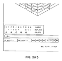
- Figures 3A, 3B, 3C and 3D show an example of a series of screen displays which occur as a designer uses the computer aided drafting system.
- Each of the Figures 3A - 3D includes the object 32 and has three datum planes A, B, and C.
- a centerline 40 which has been designated centerline datum D.
- a tolerance block 35 which is used to interface with the designer or operator of the computer aided drafting system. As shown in Figure 3A, the designer has selected "parallel" as the tolerance type. A symbol 36 which indicates that the designer has selected parallelism appears in the tolerance block 35.
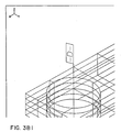
- Figure 3B shows the screen after the designer has typed in the numerical value from the keyboard 13.
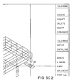
- Figure 3C shows the computer screen after the designer has selected the datum which will be referenced.
- the screen cursor 30 which appears as a circle at the intersection of two lines, is located on the datum A which was selected.
- the particular datum then appears in the tolerance block 35.
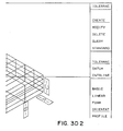
- the designer or operator takes the next step of selecting the geometric element to which the tolerance applies.
- the screen cursor is moved using the mouse 14 to the particular geometric elements or elements to which the tolerance applies.
- the mouse 14 has been used to position the screen cursor 30 on the plane to which the tolerance applies.
- a number of linkage relationships are formed when the designer or user of the computer aided drafting system designates the datum, and the particular geometric body to which a tolerance applies.
- the linkage relationships are simply a set of pointers which link the data items.
- Fig. 4 shows such a linkage relationship for a plane datum.
- the datum linkage relationship is designated by reference numeral 50.
- the particular face from which the plane datum is defined is designated by box 51.
- the plane datum symbol is represented as box 52.
- a mathematical description of the plane datum is represented as box 54.
- a pointer points from the plane datum 52 to the mathematical description of the plane datum 54.
- a pointer also points from the datum linkage relationship 50 to the face 51; another pointer points from the datum linkage relationship 50 to the plane datum symbol 52.
- the datum linkage relationship which is formed thus allows the computer aided drafting system to access the datum symbol 52 and the face from which the datum is defined, for a particular linkage relationship.
- FIG. 5A shows a center linkage relationship for a centerline 40.
- the center linkage relationship is designated by reference numeral 42. Due to the mathematics in a computer aided design system two faces are sometimes used to define a centerline 40.
- Centerline linkage relationship 42 includes a centerline symbol 43 that has a mathematical description depicted by box 44 and a first face 46 and a second face 48. Pointers point from the centerline linkage relationship 42 to the first face 46, the second face 48 and the centerline symbol 43. Another pointer points from the centerline symbol 43 to the mathematical description 44 of the centerline symbol 43.
- the centerline linkage relationship formed allows the computer aided drafting system to access the particular faces 46, 48 to which the centerline is referenced for a particular linkage relationship.
- the centerline linkage relationship allows the computer aided drafting system to access the particular centerline 40 given the particular faces 46 and 48.
- Figures 5B and 5C may similarly show the relationships for a centerplane and a centerpoint. Since the description would be so similar, Figs. 5B and 5C will not be described in detail.
- the center datum linkage relationship 60 includes a center datum symbol 62 that has a mathematical description depicted by box 64 and a center symbol which can include centerlines, centerplanes or centerpoints depicted by box 66. Pointers point from the center datum linkage relationship 60 to the center 66 and to the center datum symbol 62. Another pointer points from the center datum 62 to the mathematical description 64 of the center datum. It should be noted that a tolerance related to a center datum may be based on faces or other datums.
- the center datum linkage relationship formed allows the computer aided drafting system to access the particular center and the datum symbol 62 from which the center datum is defined, for a particular center datum linkage relationship.
- a tolerance relationship 70 is shown as an example. Included with the tolerance relationship 70 is a face 72 and a datum 74 and a tolerance description 76.
- the tolerance description 76 is the type of tolerance, such as flatness of a face.
- the tolerance description also includes the amount of tolerance that is specified with respect to a particular datum or other geometric element.
Landscapes
- Physics & Mathematics (AREA)
- Engineering & Computer Science (AREA)
- Computer Graphics (AREA)
- Geometry (AREA)
- Software Systems (AREA)
- General Physics & Mathematics (AREA)
- Theoretical Computer Science (AREA)
- Processing Or Creating Images (AREA)
Applications Claiming Priority (2)
| Application Number | Priority Date | Filing Date | Title |
|---|---|---|---|
| US55900490A | 1990-07-27 | 1990-07-27 | |
| US559004 | 1990-07-27 |
Publications (2)
| Publication Number | Publication Date |
|---|---|
| EP0468909A2 true EP0468909A2 (fr) | 1992-01-29 |
| EP0468909A3 EP0468909A3 (en) | 1993-03-31 |
Family
ID=24231892
Family Applications (1)
| Application Number | Title | Priority Date | Filing Date |
|---|---|---|---|
| EP19910480089 Withdrawn EP0468909A3 (en) | 1990-07-27 | 1991-06-18 | Method and apparatus for tolerancing three dimensional drawings |
Country Status (3)
| Country | Link |
|---|---|
| US (1) | US5771044A (fr) |
| EP (1) | EP0468909A3 (fr) |
| JP (1) | JPH07109604B2 (fr) |
Cited By (4)
| Publication number | Priority date | Publication date | Assignee | Title |
|---|---|---|---|---|
| WO1998053429A1 (fr) * | 1997-05-23 | 1998-11-26 | 3-Design L.L.C. | Procede de cotation parametrique s'articulant autour d'un systeme de reference et dispositif afferent |
| WO1999045504A1 (fr) * | 1998-03-04 | 1999-09-10 | Amada Company, Limited | Appareil et technique permettant de selectionner, afficher et repositionner a la main les dimensions |
| EP1645925A1 (fr) * | 2004-10-05 | 2006-04-12 | Solidworks Corporation | Génération automatique des annotations de tolérances |
| US7477262B2 (en) | 2004-10-05 | 2009-01-13 | Dassault Systemes Solidworks Corporation | Automatic calculation of minimum and maximum tolerance stack |
Families Citing this family (18)
| Publication number | Priority date | Publication date | Assignee | Title |
|---|---|---|---|---|
| US5894310A (en) * | 1996-04-19 | 1999-04-13 | Visionary Design Systems, Inc. | Intelligent shapes for authoring three-dimensional models |
| JP3212287B2 (ja) * | 1999-03-01 | 2001-09-25 | 富士通株式会社 | 物体断面表示装置及び方法並びにプログラム記録媒体 |
| US6825856B1 (en) * | 2000-07-26 | 2004-11-30 | Agilent Technologies, Inc. | Method and apparatus for extracting measurement information and setting specifications using three dimensional visualization |
| WO2003044452A2 (fr) * | 2001-11-16 | 2003-05-30 | Faro Technologies, Inc. | Procede et systeme aidant un utilisateur a realiser des mesures au moyen d'une machine de mesure de coordonnees |
| US20030179232A1 (en) * | 2002-03-25 | 2003-09-25 | Fousek Daniel P. | Custom drawing symbols |
| US6826510B2 (en) * | 2002-11-14 | 2004-11-30 | General Electric Company | Method, system and computer product for performing geometric dimension and tolerance stack-up analysis |
| JP2006092143A (ja) * | 2004-09-22 | 2006-04-06 | Nsk Ltd | 図面自動生成システム |
| CN100377151C (zh) * | 2005-03-11 | 2008-03-26 | 鸿富锦精密工业(深圳)有限公司 | 量测设备离线编程系统及方法 |
| US8087004B2 (en) * | 2006-09-28 | 2011-12-27 | Robert Bosch Gmbh | Drawing validation tool |
| US8249263B2 (en) * | 2008-05-15 | 2012-08-21 | International Business Machines Corporation | Method and apparatus for providing audio motion feedback in a simulated three-dimensional environment |
| US8065116B2 (en) * | 2008-10-08 | 2011-11-22 | Robert Bosch Gmbh | Systems, methods, and tools for proofing a computer-aided design object |
| US20100087943A1 (en) * | 2008-10-08 | 2010-04-08 | Robert Bosch Gmbh | Systems, methods, and tools for proofing a computer-aided design object |
| US8095341B2 (en) | 2008-10-08 | 2012-01-10 | Robert Bosch Gmbh | Systems, methods, and tools for proofing a computer-aided design object |
| CN101769729A (zh) * | 2008-12-27 | 2010-07-07 | 鸿富锦精密工业(深圳)有限公司 | 量测数据动态提示系统及方法 |
| US9651356B1 (en) | 2014-01-29 | 2017-05-16 | The United States Of America As Represented By The Secretary Of The Navy | Measuremental evaluation of dimensional tolerancing compliance of a cylindrical object |
| US9335146B1 (en) | 2014-01-29 | 2016-05-10 | The United States Of America As Represented By The Secretary Of The Navy | Dimensional measurement apparatus for a cylindrical object |
| US11556234B2 (en) * | 2020-06-12 | 2023-01-17 | Dassault Systemes Solidworks Corporation | WYSIWYG editor for creating and editing a feature control frame for geometric dimensioning and tolerancing in computer-aided design system |
| JP2025088903A (ja) * | 2023-12-01 | 2025-06-12 | 株式会社ミスミ | 情報処理装置、コンピュータプログラム、及び情報処理方法、並びに見積システム |
Family Cites Families (11)
| Publication number | Priority date | Publication date | Assignee | Title |
|---|---|---|---|---|
| US4648062A (en) * | 1985-02-01 | 1987-03-03 | International Business Machines Corporation | Method for providing an on line help facility for interactive information handling systems |
| US4736306A (en) * | 1985-04-29 | 1988-04-05 | The United States Of America As Represented By The United States Department Of Energy | System for conversion between the boundary representation model and a constructive solid geometry model of an object |
| JPH0756678B2 (ja) * | 1985-11-01 | 1995-06-14 | 株式会社日立製作所 | 対話形形状モデリングシステム |
| JPH0785271B2 (ja) * | 1986-06-27 | 1995-09-13 | 株式会社日立製作所 | 形状モデリング方法 |
| GB2230364B (en) * | 1986-08-04 | 1991-01-09 | Fmc Corp | Computer controlled display system |
| JPS63147267A (ja) * | 1986-12-11 | 1988-06-20 | Fujitsu Ltd | 2次元図形の自動寸法記入方式 |
| GB2202659B (en) * | 1987-02-23 | 1991-07-17 | Mitutoyo Corp | Coordinate measuring instrument and method of generating pattern data concerning shape of work to be measured |
| JPS63239557A (ja) * | 1987-03-27 | 1988-10-05 | Hitachi Ltd | Cad装置 |
| US4855939A (en) * | 1987-09-11 | 1989-08-08 | International Business Machines Corp. | 3D Dimensioning in computer aided drafting |
| US5038302A (en) * | 1988-07-26 | 1991-08-06 | The Research Foundation Of State University Of New York | Method of converting continuous three-dimensional geometrical representations into discrete three-dimensional voxel-based representations within a three-dimensional voxel-based system |
| US5101475A (en) * | 1989-04-17 | 1992-03-31 | The Research Foundation Of State University Of New York | Method and apparatus for generating arbitrary projections of three-dimensional voxel-based data |
-
1991
- 1991-06-18 EP EP19910480089 patent/EP0468909A3/en not_active Withdrawn
- 1991-07-11 JP JP3196068A patent/JPH07109604B2/ja not_active Expired - Lifetime
-
1993
- 1993-03-29 US US08/073,257 patent/US5771044A/en not_active Expired - Fee Related
Cited By (8)
| Publication number | Priority date | Publication date | Assignee | Title |
|---|---|---|---|---|
| WO1998053429A1 (fr) * | 1997-05-23 | 1998-11-26 | 3-Design L.L.C. | Procede de cotation parametrique s'articulant autour d'un systeme de reference et dispositif afferent |
| GB2330052A (en) * | 1997-05-23 | 1999-04-07 | Design L L C 3 | A reference based parametric dimensioning method and system |
| GB2330052B (en) * | 1997-05-23 | 2002-01-09 | Design L L C 3 | A reference based parametric dimensioning method and system |
| WO1999045504A1 (fr) * | 1998-03-04 | 1999-09-10 | Amada Company, Limited | Appareil et technique permettant de selectionner, afficher et repositionner a la main les dimensions |
| US6904393B2 (en) | 1998-03-04 | 2005-06-07 | Amada Company, Limited | Apparatus and method for manually selecting, displaying, and repositioning dimensions of a part model |
| EP1645925A1 (fr) * | 2004-10-05 | 2006-04-12 | Solidworks Corporation | Génération automatique des annotations de tolérances |
| US7477262B2 (en) | 2004-10-05 | 2009-01-13 | Dassault Systemes Solidworks Corporation | Automatic calculation of minimum and maximum tolerance stack |
| US7590497B2 (en) | 2004-10-05 | 2009-09-15 | Dassault Systemes Solidworks Corporation | Automatic generation of tolerance schemes |
Also Published As
| Publication number | Publication date |
|---|---|
| JPH07109604B2 (ja) | 1995-11-22 |
| US5771044A (en) | 1998-06-23 |
| EP0468909A3 (en) | 1993-03-31 |
| JPH06342458A (ja) | 1994-12-13 |
Similar Documents
| Publication | Publication Date | Title |
|---|---|---|
| US5771044A (en) | Method and apparatus for tolerancing three dimensional drawings | |
| US4855939A (en) | 3D Dimensioning in computer aided drafting | |
| US5138697A (en) | Graphic data conversion method | |
| US5649080A (en) | Apparatus and method for converting line segment data to three-dimensional data | |
| US5010502A (en) | Method and apparatus for generating representations of 3-dimensional objects | |
| US7119805B2 (en) | Three-dimensional CAD attribute information presentation | |
| US4807143A (en) | System for forming design pattern data | |
| EP1038272B1 (fr) | Appareil et methode pour entree des donnees pour un modele cintrage de toles | |
| US4706187A (en) | Method of and apparatus for preparing numerical control data for inserting components | |
| US20030210244A1 (en) | Information processing apparatus and method | |
| GB2190268A (en) | C.a.d. | |
| US11556234B2 (en) | WYSIWYG editor for creating and editing a feature control frame for geometric dimensioning and tolerancing in computer-aided design system | |
| EP0681243B1 (fr) | Procédé pour effectuer des opérations booléennes un des objets géométriques dans un système C.A.O. (Conception Assistée par Ordinateur) | |
| Nyemba | Computer aided design: Engineering design and modeling using AutoCAD | |
| EP1091325B1 (fr) | Paramètres définissables par l'utilisateur servant pour le calcul d'analyse d'éléments finis dans un programme CAD | |
| US5586232A (en) | Projection view creation method with vector discrimination onto plane-represented curved surfaces | |
| Ewald et al. | Final report of the GSPC state-of-the-art subcommittee | |
| US20060071948A1 (en) | 3D font-engine | |
| JP3157474B2 (ja) | カム設計処理装置及び方法 | |
| Rose et al. | Intuitive and interactive modification of large finite element models | |
| EP1830323A2 (fr) | Appareil et procédé pour la gestion et la distribution d'un modèle et de fabrication d'informations dans une installation de fabrication de feuilles métalliques | |
| Venkatesh | Interactive graphics software for the generation of cubic spline and postprocessor for NC machining | |
| Кальченко et al. | PowerShape in automobile transport. Methodological instructions for practical work from the selective discipline" Computer modeling and design of cars and engines" for students majoring in J8" Automobile transport" for the second (master's) level of higher education full-time and part-time studies | |
| JP2526092B2 (ja) | Cadシステムにおける寸法チェック方式 | |
| JP2889760B2 (ja) | 文字群と図形とを組み合わせる電子組版装置 |
Legal Events
| Date | Code | Title | Description |
|---|---|---|---|
| PUAI | Public reference made under article 153(3) epc to a published international application that has entered the european phase |
Free format text: ORIGINAL CODE: 0009012 |
|
| AK | Designated contracting states |
Kind code of ref document: A2 Designated state(s): DE FR GB |
|
| 17P | Request for examination filed |
Effective date: 19920521 |
|
| PUAL | Search report despatched |
Free format text: ORIGINAL CODE: 0009013 |
|
| AK | Designated contracting states |
Kind code of ref document: A3 Designated state(s): DE FR GB |
|
| 17Q | First examination report despatched |
Effective date: 19970623 |
|
| STAA | Information on the status of an ep patent application or granted ep patent |
Free format text: STATUS: THE APPLICATION IS DEEMED TO BE WITHDRAWN |
|
| 18D | Application deemed to be withdrawn |
Effective date: 19980106 |