EP0469251A1 - Appareil de chauffage avec la combustion catalytique - Google Patents
Appareil de chauffage avec la combustion catalytique Download PDFInfo
- Publication number
- EP0469251A1 EP0469251A1 EP91107373A EP91107373A EP0469251A1 EP 0469251 A1 EP0469251 A1 EP 0469251A1 EP 91107373 A EP91107373 A EP 91107373A EP 91107373 A EP91107373 A EP 91107373A EP 0469251 A1 EP0469251 A1 EP 0469251A1
- Authority
- EP
- European Patent Office
- Prior art keywords
- catalytic combustion
- heating apparatus
- infrared
- apparatus operating
- radiation heating
- Prior art date
- Legal status (The legal status is an assumption and is not a legal conclusion. Google has not performed a legal analysis and makes no representation as to the accuracy of the status listed.)
- Granted
Links
Images


Classifications
-
- F—MECHANICAL ENGINEERING; LIGHTING; HEATING; WEAPONS; BLASTING
- F23—COMBUSTION APPARATUS; COMBUSTION PROCESSES
- F23D—BURNERS
- F23D14/00—Burners for combustion of a gas, e.g. of a gas stored under pressure as a liquid
- F23D14/12—Radiant burners
- F23D14/18—Radiant burners using catalysis for flameless combustion
Definitions
- This invention relates to an apparatus for heating by means of infrared radiation, which can in particular be used in the various applications in the home owing to its safety, reliability, convenience and low-consumption properties.
- Cooking surfaces are well-known in household appliance burners with related caps, pan-support ribs and a underlying hob made of stainless steel or enamelled steel sheet. These cooking surfaces usually have serious drawbacks in connection with both safety and cleanability considerations, since their operation is generally associated with a considerable release of carbon and nitrogen oxides into the atmosphere and, furthermore, they are notoriously connected with a substantial risk of their flames extinguishing due to food overflowing from pans placed thereupon, or a number of different causes, with the well-known, very dangerous consequence of toxic and flammable gas escaping unburnt into closed rooms or spaces.
- the Italian patent application no. 45760 A/89 discloses heating apparatuses, which are intended in particular for food cooking purposes and are embodied through the use of closed-type conduits that are filled with catalytic material and are flowed through by a gas mixture. That enables a combustion apparatus to be obtained which, at least as far as the combustion of fuel gas is concerned, eliminates or reduces to a minumum the afore mentioned environmental pollution effects.
- a catalytic combustion process is used also in the apparatus according to this invention.
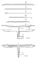
- the fuel gas already duly pre-mixed with air to stoichiometric proportions, is introduced in a preferably flat and horizontal expansion pre-chamber 9, from which said fuel gas mixture propagates in a uniform and continuous way, along the desired path, into a diffusion chamber 10, a face of which, preferably the upper one, is defined by the catalyst element 6.
- Any desired pattern or shape of the combustion surface can be brought about by simply acting on the shape and the size of the diffusion chamber 10 and, therefore, on the flame distributor 5 which forms a wall thereof.
- the catalyst element 6 the structure of which can be compared with the one of a wire-gauze with a suitably selected mesh-size, is treated with a process of the so-called "WASH COAT" type for the deposition of the catalytic material. It is also preferable for said element 6 to be flat and horizontal and it is of importance that it has a high thermal conductivity in order to ensure a uniform heat distribution.
- the fuel gas mixture diffuses into said catalyst element 6, which can for example be made in the form of a thin wire-gauze and which shall be brought to its activation temperature in order to initiate the reaction and start the combustion.
- a variously shaped, electrically fed incandescence-type ignition device 20 which is located near the inlet ports for the air/gas mixture and in contact with the wire-gauze catalyst element 6.
- the high thermal conductivity of the wire-gauze structure ensures an affective heating of the area involved in the initial activation of the catalytic material.
- the ignition device After the reaction process has been initiated in this way, the ignition device is de-energized, or switched off. This whole system provided to ensure ignition (from cold conditions) completes its start- up cycle within a few seconds. If, on the other hand, it is desired to reignite the burner within a few minutes from its extinction, the ignition process will take place also without an intervention of the ignition device, since a minimum residual heat of the wire-gauze structure (ie. a temperature of 250 to 300 deg C) will be perfectly sufficient to reinitiate the reaction and, therefore, the combustion process.
- a minimum residual heat of the wire-gauze structure ie. a temperature of 250 to 300 deg C
- reaction initiation temperature should be as low as possible.
- a palladium and/or platinum- based catalyst is preferred.
- the heat generated and released by the catalyst element 6 is then collected by the inner face of an intercepting surface 8 which encloses said catalyst element 6 that is possibly kept in its position by a holding ring 7.
- Said intercepting surface 8 conducts heat towards the outside and, therefore, its outer face acts as the actual, final heating element.
- Said surface 8 further to acting as the intercepting and heat-transmitting element, can be formed to tightly cover and seal the catalyst element 6 and, as a consequence, is adapted to at the same time acts also as a "cover” to retain flue gases and convey into flue exhaust channels that will be provided appropriately.
- the same surface 8 is closed by having its outer edge fitting against a retaining cap 3 which, through a manifold chamber 16, conveys flue gases into an exhaust fitting 2.
- the air/gas mixture inlet fitting 1 splits open in such a way as to form the partition 4 which delimitates the expansion pre-chamber 9 on the one side and the flue gas collecting chamber 16 on the other one.
- the expansion pre-chamber 9 itself can be delimitated, on its other side, by the flame distributor 5, which in turn delimitates, with its opposite face, the diffusion chamber 10.
- Some parts of said flame distributor 5 can be made to adhere to the catalyst element 6, thereby masking the combustion zones at will and, therefore, achieving any desired combustion pattern.
- a very particular advantage thereof which anyone skilled in the art would have no difficulty in implementing, resides in the possibility of achieving a heating element having just the desired heat emission properties, in terms of thermal power emitted by said element either in a concentrated form or distributed in specific areas, by simply implementing a plurality of individual diffusion chambers of appropriate shape, size and input rating, as well as arranged according to a corresponding pattern.
- the flue gases collected by the intercepting surface 8 can be exhausted through appropriately drilled holes or openings 12 along the outer edge of the partition 4.
- the inlet of the air/gas mixture is governed by a valve which is controlled from the outside.
- An appropriate Venturi tube can be used to obtain the correct air and gas mixture or, as an alternative solution, a fan can be used in view of overcoming the flow resistance opposed by the catalyst material.
- the flue gas temperature is intrinsecally relatively low. However, through an appropriate design it can be further reduced and kept at approx. 100 deg C.
Landscapes
- Engineering & Computer Science (AREA)
- Chemical & Material Sciences (AREA)
- Chemical Kinetics & Catalysis (AREA)
- Combustion & Propulsion (AREA)
- Mechanical Engineering (AREA)
- General Engineering & Computer Science (AREA)
- Gas Burners (AREA)
- Incineration Of Waste (AREA)
Applications Claiming Priority (2)
| Application Number | Priority Date | Filing Date | Title |
|---|---|---|---|
| IT45729A IT1239151B (it) | 1990-05-29 | 1990-05-29 | Dispositivo di riscaldamento utilizzante la combustione catalitica |
| IT4572990 | 1990-05-29 |
Publications (2)
| Publication Number | Publication Date |
|---|---|
| EP0469251A1 true EP0469251A1 (fr) | 1992-02-05 |
| EP0469251B1 EP0469251B1 (fr) | 1994-07-20 |
Family
ID=11257823
Family Applications (1)
| Application Number | Title | Priority Date | Filing Date |
|---|---|---|---|
| EP91107373A Expired - Lifetime EP0469251B1 (fr) | 1990-05-29 | 1991-05-07 | Appareil de chauffage avec la combustion catalytique |
Country Status (4)
| Country | Link |
|---|---|
| EP (1) | EP0469251B1 (fr) |
| DE (1) | DE69102952T2 (fr) |
| ES (1) | ES2062609T3 (fr) |
| IT (1) | IT1239151B (fr) |
Cited By (2)
| Publication number | Priority date | Publication date | Assignee | Title |
|---|---|---|---|---|
| US7721726B2 (en) | 2006-01-03 | 2010-05-25 | Lg Electronics Inc. | Gas radiation burner |
| WO2018095988A1 (fr) * | 2016-11-25 | 2018-05-31 | Frima International Ag | Système de brûleur pour appareil de cuisson et procédé permettant de faire fonctionner un système de brûleur pour appareil de cuisson |
Citations (4)
| Publication number | Priority date | Publication date | Assignee | Title |
|---|---|---|---|---|
| AT211987B (de) * | 1956-03-29 | 1960-11-25 | Schweiz Gasapp Fabrik Solothur | Heizvorrichtung |
| US3067811A (en) * | 1956-07-02 | 1962-12-11 | Otto Bernz Co Inc | Gas burner |
| US3799142A (en) * | 1972-04-26 | 1974-03-26 | F Jensen | Method and apparatus for sequestering open flame combustion gas |
| US4189294A (en) * | 1977-10-18 | 1980-02-19 | Comstock & Wescott Inc. | Flameless combustion burner and method of operation |
-
1990
- 1990-05-29 IT IT45729A patent/IT1239151B/it active IP Right Grant
-
1991
- 1991-05-07 DE DE69102952T patent/DE69102952T2/de not_active Expired - Fee Related
- 1991-05-07 EP EP91107373A patent/EP0469251B1/fr not_active Expired - Lifetime
- 1991-05-07 ES ES91107373T patent/ES2062609T3/es not_active Expired - Lifetime
Patent Citations (4)
| Publication number | Priority date | Publication date | Assignee | Title |
|---|---|---|---|---|
| AT211987B (de) * | 1956-03-29 | 1960-11-25 | Schweiz Gasapp Fabrik Solothur | Heizvorrichtung |
| US3067811A (en) * | 1956-07-02 | 1962-12-11 | Otto Bernz Co Inc | Gas burner |
| US3799142A (en) * | 1972-04-26 | 1974-03-26 | F Jensen | Method and apparatus for sequestering open flame combustion gas |
| US4189294A (en) * | 1977-10-18 | 1980-02-19 | Comstock & Wescott Inc. | Flameless combustion burner and method of operation |
Cited By (3)
| Publication number | Priority date | Publication date | Assignee | Title |
|---|---|---|---|---|
| US7721726B2 (en) | 2006-01-03 | 2010-05-25 | Lg Electronics Inc. | Gas radiation burner |
| WO2018095988A1 (fr) * | 2016-11-25 | 2018-05-31 | Frima International Ag | Système de brûleur pour appareil de cuisson et procédé permettant de faire fonctionner un système de brûleur pour appareil de cuisson |
| US11160417B2 (en) | 2016-11-25 | 2021-11-02 | Rational International Ag | Burner system for a cooking appliance, and method for operating a burner system for a cooking appliance |
Also Published As
| Publication number | Publication date |
|---|---|
| IT1239151B (it) | 1993-09-28 |
| ES2062609T3 (es) | 1994-12-16 |
| DE69102952T2 (de) | 1994-12-08 |
| IT9045729A1 (it) | 1991-11-29 |
| IT9045729A0 (it) | 1990-05-29 |
| EP0469251B1 (fr) | 1994-07-20 |
| DE69102952D1 (de) | 1994-08-25 |
Similar Documents
| Publication | Publication Date | Title |
|---|---|---|
| US5909533A (en) | Electric cooking oven with infrared gas broiler | |
| US3364912A (en) | Self-cleaning gas oven | |
| CA1238796A (fr) | Friteuse | |
| US3783854A (en) | Flow-through self-cleaning gas oven with heat exchanger | |
| US6823859B2 (en) | Flat heating surface type gas stove | |
| US6776151B2 (en) | Positive air flow apparatus for infrared gas broiler | |
| US20100095951A1 (en) | Parallel tube burner with improved cooling and reduced size | |
| JPS5912930B2 (ja) | ガスレンジ | |
| US7631640B2 (en) | Radiant burner | |
| US3507265A (en) | Self-cleaning gas cooking oven | |
| CA2944790C (fr) | Bruleur infrarouge destine a des appareils de nettoyage a pression | |
| JP2006046884A (ja) | ガスコンロ | |
| US3200874A (en) | Premixed gas infrared burner | |
| EP0469251B1 (fr) | Appareil de chauffage avec la combustion catalytique | |
| US3812838A (en) | Oven combustion products distribution system | |
| US2733705A (en) | Open flame heating unit with combus- | |
| US20020157659A1 (en) | Gas broiler | |
| US3266480A (en) | Warm air furnace | |
| RU2052722C1 (ru) | Газогорелочное устройство | |
| KR100751418B1 (ko) | 가스 버너 및 이를 이용한 히팅장치 | |
| US1808866A (en) | Gas oven construction | |
| CN219933991U (zh) | 一种高效率VOCs处理设备 | |
| KR100751417B1 (ko) | 가스 버너 및 이를 이용한 히팅장치 | |
| US238301A (en) | Burner for gas-stoves | |
| JPS5592823A (en) | Portable cooking stove |
Legal Events
| Date | Code | Title | Description |
|---|---|---|---|
| PUAI | Public reference made under article 153(3) epc to a published international application that has entered the european phase |
Free format text: ORIGINAL CODE: 0009012 |
|
| AK | Designated contracting states |
Kind code of ref document: A1 Designated state(s): DE ES FR GB IT SE |
|
| 17P | Request for examination filed |
Effective date: 19920222 |
|
| 17Q | First examination report despatched |
Effective date: 19930316 |
|
| ITF | It: translation for a ep patent filed | ||
| GRAA | (expected) grant |
Free format text: ORIGINAL CODE: 0009210 |
|
| AK | Designated contracting states |
Kind code of ref document: B1 Designated state(s): DE ES FR GB IT SE |
|
| REF | Corresponds to: |
Ref document number: 69102952 Country of ref document: DE Date of ref document: 19940825 |
|
| ET | Fr: translation filed | ||
| EAL | Se: european patent in force in sweden |
Ref document number: 91107373.2 |
|
| PLBE | No opposition filed within time limit |
Free format text: ORIGINAL CODE: 0009261 |
|
| STAA | Information on the status of an ep patent application or granted ep patent |
Free format text: STATUS: NO OPPOSITION FILED WITHIN TIME LIMIT |
|
| 26N | No opposition filed | ||
| REG | Reference to a national code |
Ref country code: ES Ref legal event code: PC2A Owner name: ELECTROLUX ZANUSSI ELETTRODOMESTICI, S.P.A. |
|
| PGFP | Annual fee paid to national office [announced via postgrant information from national office to epo] |
Ref country code: FR Payment date: 19970411 Year of fee payment: 7 |
|
| PGFP | Annual fee paid to national office [announced via postgrant information from national office to epo] |
Ref country code: SE Payment date: 19970416 Year of fee payment: 7 |
|
| PGFP | Annual fee paid to national office [announced via postgrant information from national office to epo] |
Ref country code: GB Payment date: 19970417 Year of fee payment: 7 |
|
| PGFP | Annual fee paid to national office [announced via postgrant information from national office to epo] |
Ref country code: DE Payment date: 19970423 Year of fee payment: 7 |
|
| PGFP | Annual fee paid to national office [announced via postgrant information from national office to epo] |
Ref country code: ES Payment date: 19970513 Year of fee payment: 7 |
|
| PG25 | Lapsed in a contracting state [announced via postgrant information from national office to epo] |
Ref country code: GB Free format text: LAPSE BECAUSE OF NON-PAYMENT OF DUE FEES Effective date: 19980507 |
|
| PG25 | Lapsed in a contracting state [announced via postgrant information from national office to epo] |
Ref country code: SE Free format text: LAPSE BECAUSE OF NON-PAYMENT OF DUE FEES Effective date: 19980508 Ref country code: ES Free format text: LAPSE BECAUSE OF EXPIRATION OF PROTECTION Effective date: 19980508 |
|
| PG25 | Lapsed in a contracting state [announced via postgrant information from national office to epo] |
Ref country code: FR Free format text: LAPSE BECAUSE OF NON-PAYMENT OF DUE FEES Effective date: 19980531 |
|
| REG | Reference to a national code |
Ref country code: ES Ref legal event code: PC2A |
|
| GBPC | Gb: european patent ceased through non-payment of renewal fee |
Effective date: 19980507 |
|
| EUG | Se: european patent has lapsed |
Ref document number: 91107373.2 |
|
| PG25 | Lapsed in a contracting state [announced via postgrant information from national office to epo] |
Ref country code: DE Free format text: LAPSE BECAUSE OF NON-PAYMENT OF DUE FEES Effective date: 19990302 |
|
| REG | Reference to a national code |
Ref country code: FR Ref legal event code: ST |
|
| REG | Reference to a national code |
Ref country code: ES Ref legal event code: FD2A Effective date: 20000301 |
|
| PG25 | Lapsed in a contracting state [announced via postgrant information from national office to epo] |
Ref country code: IT Free format text: LAPSE BECAUSE OF NON-PAYMENT OF DUE FEES;WARNING: LAPSES OF ITALIAN PATENTS WITH EFFECTIVE DATE BEFORE 2007 MAY HAVE OCCURRED AT ANY TIME BEFORE 2007. THE CORRECT EFFECTIVE DATE MAY BE DIFFERENT FROM THE ONE RECORDED. Effective date: 20050507 |