EP0469268B1 - Verbindung zwischen dem Auslauf eines metallurgischen Gefässes und einem Schutzrohr oder Eintauchausguss - Google Patents
Verbindung zwischen dem Auslauf eines metallurgischen Gefässes und einem Schutzrohr oder Eintauchausguss Download PDFInfo
- Publication number
- EP0469268B1 EP0469268B1 EP91109446A EP91109446A EP0469268B1 EP 0469268 B1 EP0469268 B1 EP 0469268B1 EP 91109446 A EP91109446 A EP 91109446A EP 91109446 A EP91109446 A EP 91109446A EP 0469268 B1 EP0469268 B1 EP 0469268B1
- Authority
- EP
- European Patent Office
- Prior art keywords
- connection
- protective tube
- outlet
- immersion nozzle
- annular space
- Prior art date
- Legal status (The legal status is an assumption and is not a legal conclusion. Google has not performed a legal analysis and makes no representation as to the accuracy of the status listed.)
- Expired - Lifetime
Links
- 238000007654 immersion Methods 0.000 title claims abstract description 29
- 230000001681 protective effect Effects 0.000 title claims abstract description 19
- 238000007789 sealing Methods 0.000 claims abstract description 37
- 239000007789 gas Substances 0.000 claims abstract description 20
- 239000011261 inert gas Substances 0.000 claims abstract description 9
- 125000006850 spacer group Chemical group 0.000 claims description 8
- 239000000919 ceramic Substances 0.000 claims description 4
- 230000035699 permeability Effects 0.000 claims description 4
- 239000000835 fiber Substances 0.000 claims description 2
- 239000000463 material Substances 0.000 claims 1
- 239000004575 stone Substances 0.000 description 6
- 239000002657 fibrous material Substances 0.000 description 4
- 239000002184 metal Substances 0.000 description 2
- QVGXLLKOCUKJST-UHFFFAOYSA-N atomic oxygen Chemical compound [O] QVGXLLKOCUKJST-UHFFFAOYSA-N 0.000 description 1
- 238000005266 casting Methods 0.000 description 1
- 239000000155 melt Substances 0.000 description 1
- 238000012544 monitoring process Methods 0.000 description 1
- 239000001301 oxygen Substances 0.000 description 1
- 229910052760 oxygen Inorganic materials 0.000 description 1
- 239000002245 particle Substances 0.000 description 1
Images
Classifications
-
- B—PERFORMING OPERATIONS; TRANSPORTING
- B22—CASTING; POWDER METALLURGY
- B22D—CASTING OF METALS; CASTING OF OTHER SUBSTANCES BY THE SAME PROCESSES OR DEVICES
- B22D41/00—Casting melt-holding vessels, e.g. ladles, tundishes, cups or the like
- B22D41/50—Pouring-nozzles
- B22D41/502—Connection arrangements; Sealing means therefor
Definitions
- the invention relates to a connection between the outlet of a metallurgical vessel and an adjoining protective tube or an immersion spout, the outlet and the protective tube or the immersion spout being connected to one another by a seat and in the region of the seat an annular space concentric to this with a feed line for a Inert gas is arranged and a seal is provided.
- DE 36 20 413 C2 proposes an expandable fiber felt for pouring closures and gas inlets on metallurgical vessels.
- the object of the invention is to simplify the sealing in a connection of the type mentioned and to achieve tightness monitoring.
- the above object is achieved in a connection of the type mentioned at the outset in that a compressible ring is arranged as a sealing ring above and below the annular space and that a display device for a gas pressure present in the annular space is arranged in the feed line of the inert gas.
- the sealing rings ensure the necessary tightness of the seat even if there are unevenness between the outlet and the protective tube or immersion spout. In cooperation with the gas pressure of the inert gas prevailing in the annular space, the sealing rings ensure that the leaking metal melt does not come into contact with air and therefore does not oxidize.
- the gas pressure in the annulus is monitored by the display device. If either the upper sealing ring or the lower sealing ring should leak, an indication is given. As long as only one of the sealing rings leaks, there is still no danger that the molten metal will come into contact with air. An indication is therefore given even before a state in which both sealing rings are leaking and thus atmospheric oxygen is sucked in by the escaping melt through the seat.
- the compressible sealing rings preferably consist of ceramic fiber material. They are connected to one another in particular by spacer webs bridging the annular space. This makes it possible to assemble both rings as a structural unit. These can be attached to the outlet or to the protective tube or the immersion spout before the protective tube or immersion spout is attached. In an embodiment of the invention, a one-piece ring component forms both rings and possibly the spacer webs.
- the two sealing rings can be attached to the outlet or to the protective tube or the immersion spout before the protective tube or immersion spout is attached.
- the lower sealing ring preferably lies against a step of the protective tube or immersion spout. This makes it easy to achieve the correct position of the sealing rings during assembly.
- the sealing rings have a certain gas permeability. Because of the gas overpressure of the inert gas prevailing in the annular space, however, this does not result in air being sucked in by the melt.
- a different gas permeability of the compressible sealing rings results in a directed gas flow, preferably into the protective tube or the immersion spout.
- a conical outlet stone (2) is attached to the bottom (1) of a metallurgical vessel.
- the sealing rings (5, 6) are compressible and consist of ceramic fiber material.
- a radial channel (9) of the immersion spout (3) opens into the annular space (7).
- a gas line (10) for inert gas is connected to this.
- a display device (11) for the gas pressure prevailing in the annular space (7) is located in the gas line (10).
- the two sealing rings (5, 6) are connected to each other via spacers (12). These extend through the annular space (7) without closing it off.
- the two sealing rings (5, 6) and the spacer webs (12) are made as a one-piece component from the ceramic fiber material.
- the lower sealing ring (6) sits on a step (13) formed in the immersion spout (3).
- the immersion nozzle (3) is pushed onto the outlet stone (2) and fastened in this position in a manner known per se.
- the fiber material of the sealing rings (5, 6) is compressed.
- the gas line (10) can be connected.
- the annular space (7) is charged with inert gas.
- the pressure of the sealing rings (5, 6) and the negative pressure prevailing during casting in the immersion spout (3) a certain value arises on the display device (11), which is formed by a pressure gauge Overpressure.
Landscapes
- Mechanical Engineering (AREA)
- Engineering & Computer Science (AREA)
- Treatment Of Steel In Its Molten State (AREA)
- Continuous Casting (AREA)
- Furnace Charging Or Discharging (AREA)
- Furnace Housings, Linings, Walls, And Ceilings (AREA)
- Vertical, Hearth, Or Arc Furnaces (AREA)
- Waste-Gas Treatment And Other Accessory Devices For Furnaces (AREA)
- Carbon Steel Or Casting Steel Manufacturing (AREA)
- Manufacture And Refinement Of Metals (AREA)
- Sealing Devices (AREA)
- Casting Support Devices, Ladles, And Melt Control Thereby (AREA)
- Cable Accessories (AREA)
- Measuring Fluid Pressure (AREA)
- Discharge Heating (AREA)
- Pressure Vessels And Lids Thereof (AREA)
Description
- Die Erfindung betrifft eine Verbindung zwischen dem Auslauf eines metallurgischen Gefäßes und einem daran anschließenden Schutzrohr oder einem Eintauchausguß, wobei der Auslauf und das Schutzrohr bzw. der Eintauchausguß durch einen Sitz miteinander verbunden sind und im Bereich des Sitzes ein zu diesem konzentrischer Ringraum mit Zuleitung für ein Inertgas angeordnet ist und eine Dichtung vorgesehen ist.
- Eine derartige Verbindung ist in der DE 32 26 047 C2 beschrieben. Dort ist der Sitz ein Paßsitz. Bei einem solchen ist die gewünschte Gasdichtigkeit kaum zu gewährleisten. Schon kleinere Partikel im Paßsitz beeinträchtigen die Gasdichtigkeit beträchtlich. Außerdem führt der Paßsitz dazu, daß das Schutzrohr bzw. der Eintauchausguß beim Abnehmen vom Auslaufkonus klemmt und bei größerer Krafteinwirkung brechen kann.
- In der DE 36 20 413 C2 ist fur Ausgußverschlüsse und Gaseinführungen an metallurgischen Gefäßen ein Blähfaserfilz vorgeschlagen.
- Aufgabe der Erfindung ist es, bei einer Verbindung der eingangs genannten Art die Abdichtung zu vereinfachen und eine Dichtigkeitsüberwachung zu erreichen.
- Erfindungsgemäß ist obige Aufgabe bei einer Verbindung der eingangs genannten Art dadurch gelöst, daß oberhalb und unterhalb des Ringraums ein kompressibler Ring als Dichtring angeordnet ist und daß in der Zuleitung des Inertgases eine Anzeigeeinrichtung für einen im Ringraum anstehenden Gasdruck angeordnet ist.
- Die Dichtringe gewährleisten die notwendige Dichtigkeit des Sitzes auch dann, wenn zwischen dem Auslauf ud dem Schutzrohr bzw. Eintauchausguß Unebenheiten bestehen. Im Zusammenwirken mit dem im Ringraum herrschenden Gasdruck des Inertgases stellen die Dichtringe sicher, daß die auslaufende Metallschmelze nicht mit Luft in Berührung kommt und also nicht oxidiert.
- Der im Ringraum anstehende Gasdruck wird durch die Anzeigeeinrichtung überwacht. Wenn entweder der obere Dichtring oder der untere Dichtring undicht werden sollten, erfolgt eine Anzeige. Solange nur einer der Dichtringe undicht wird, besteht noch nicht die Gefahr, daß die Metallschmelze mit Luft in Berührung kommt. Eine Anzeige erfolgt also schon vor einem Zustand, in dem beide Dichtringe undicht sind und damit Luftsauerstoff von der auslaufenden Schmelze durch den Sitz angesaugt wird.
- Vorzugsweise bestehen die kompressiblen Dichtringe aus keramischem Fasermaterial. Sie sind insbesondere durch den Ringraum überbrükkende Distanzstege miteinander verbunden. Dadurch ist es möglich, beide Ringe als Baueinheit zu montieren. Diese können vor dem Ansetzen des Schutzrohrs bzw. Eintauchausgusses an dem Auslauf an diesem oder an dem Schutzrohr bzw. dem Eintauchausguß befestigt sein. In Ausgestaltung der Erfindung bildet ein einstückiges Ringbauteil beide Ringe und gegebenenfalls die Distanzstege.
- Die beiden Dichtringe können vor dem Ansetzen des Schutzrohres bzw. Eintauchausgusses an den Auslauf an diesem oder an dem Schutzrohr bzw. dem Eintauchausguß befestigt sein.
- Vorzugsweise liegt der untere Dichtring an einer Stufe des Schutzrohrs bzw. Eintauchausgusses an. Es ist dadurch die richtige Lage der Dichtringe bei der Montage einfach zu erreichen.
- Die Dichtringe weisen in der Praxis eine gewisse Gasdurchlässigkeit auf. Wegen des im Ringraum herrschenden Gas-Überdrucks des Inertgases führt dies jedoch nicht dazu, daß Luft von der Schmelze angesaugt wird. In Ausgestaltung der Erfindung entsteht durch eine unterschiedliche Gasdurchlässigkeit der kompressiblen Dichtringe ein gerichteter Gasstrom, vorzugsweise in das Schutzrohr bzw. den Eintauchausguß.
- Ein Ausführungsbeispiel der Erfindung ergibt sich aus der folgenden Beschreibung. In der Zeichnung zeigen:
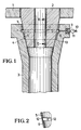
- Figur 1 einen Längsschnitt einer Verbindung zwischen einem Auslaufstein und einem Eintauchausguß im Längsschnitt und
- Figur 2 einen Schnitt der Dichtringe längs der Linie 11-11 nach Figur 1.
- Am Boden (1) eines metallurgischen Gefäßes ist ein konischer Auslaufstein (2) befestigt. Über diesen ist ein Eintauchausguß (3) mit seinem sich entsprechend der Konizität des Auslaufsteins (2) erweiternden oberen Ende (4) geschoben.
- Zwischen dem Eintauchausguß (3) und dem Auslaufstein (2) sitzen ein oberer Dichtring (5) und ein unterer Dichtring (6). Die Dichtringe (5, 6) sind kompressibel und bestehen aus keramischem Fasermaterial.
- Zwischen den Dichtringen (5, 6) besteht ein Ringraum (7), der durch eine Stufung (8) des Eintauchausgusses (3) erweitert ist.
- In den Ringraum (7) mündet ein radialer Kanal (9) des Eintauchausgusses (3). An diesen ist eine Gasleitung (10) für Inertgas angeschlossen. In der Gasleitung (10) liegt eine Anzeigeeinrichtung (11) für den im Ringraum (7) herrschenden Gasdruck.
- Die beiden Dichtringe (5, 6) sind über Distanzstege (12) miteinander verbunden. Diese erstrekken sich durch den Ringraum (7), ohne diesen abzusperren. Die beiden Dichtringe (5, 6) und die Distanzstege (12) sind als einstückiges Bauteil aus dem keramischen Fasermaterial hergestellt. Der untere Dichtring (6) sitzt auf einer in dem Eintauchausguß (3) ausgebildeten Stufe (13) auf.
- Die Montage des Eintauchausgusses (3) an dem Auslaufstein (2) geschieht etwa folgendermaßen:
- In den Eintauchausguß (3) wird die Baueinheit, bestehend aus oberem und unterem Dichtring (5, 6) und den Distanzstegen (12), eingeschoben, bis der untere Dichtring (6) auf der Stufe (13) aufsteht. Die Distanzstege (12) liegen dann im Bereich der den Ringraum (7) erweiternden Stufung (8).
- Anschließend wird der Eintauchausguß (3) auf den Auslaufstein (2) geschoben und in dieser Stellung in an sich bekannter Weise befestigt. Das Fasermaterial der Dichtringe (5, 6) wird dabei komprimiert. Danach läßt sich die Gasleitung (10) anschließen.
- Im Betrieb wird der Ringraum (7) mit Inertgas beaufschlagt. Je nach der Gasdurchlässigkeit der Dichtringe (5, 6), der Pressung der Dichtringe (5, 6) und dem beim Gießen im Eintauchausguß (3) herrschenden Unterdruck stellt sich an der Anzeigeeinrichtung (11), die von einem Druckmesser gebildet ist, ein bestimmter Überdruck ein.
- Tritt am Dichtring (5) oder am Dichtinrg (6) eine Undichtigkeit auf, dann sinkt der Gasdruck ab und die Anzeigeeinrichtung (11) gibt ein Alarmsignal ab.
Claims (8)
dadurch gekennzeichnet,
daß oberhalb und unterhalb des Ringraums (7) ein kompressibler Ring (5, 6) als Dichtring angeordnet ist und daß in der Zuleitung (10) des Inertgases eine Anzeigeeinrichtung (11) für einen im Ringraum (7) anstehenden Gasdruck angeordnet ist.
dadurch gekennzeichnet,
daß die kompressiblen Dichtringe (5, 6) aus keramischem Fasermaterial bestehen.
dadurch gekennzeichnet,
daß der obere und der untere Dichtring (5, 6) durch den Ringraum (7) überbrückende Distanzstege (12) miteinander verbunden sind.
dadurch gekennzeichnet,
daß die kompressiblen Ringe (5, 6) vor dem Verbinden von Auslauf (2) und Schutzrohr bzw. Eintauchausguß (3) auf dem Auslauf (2) befestigt sind.
dadurch gekennzeichnet,
daß die kompressiblen Ringe (5, 6) vor dem Verbinden von Auslauf (2) und Schutzrohr bzw. Eintauchausguß (3) in dem Schutzrohr bzw. Eintauchausguß (3) befestigt sind.
dadurch gekennzeichnet,
daß der untere Dichtring (6) an einer Stufe (13) des Schutzrohrs bzw. Eintauchausgusses (3) anliegt.
dadurch gekennzeichnet,
daß durch unterschiedliche Gasdurchlässigkeit der kompressiblen Dichtringe (5, 6) ein gerichteter Gasstrom, vorzugsweise in das Schutzrohr bzw. in den Eintauchausguß (3), entsteht.
dadurch gekennzeichnet,
daß ein einstückiges Ringbauteil die beiden Dichtringe (5, 6) und gegebenenefalls die Distanzstege (12) bildet.
Applications Claiming Priority (2)
| Application Number | Priority Date | Filing Date | Title |
|---|---|---|---|
| DE4024520A DE4024520A1 (de) | 1990-08-02 | 1990-08-02 | Verbindung zwischen dem auslauf eines metallurgischen gefaesses und einem schutzrohr oder eintauchausguss |
| DE4024520 | 1990-08-02 |
Publications (4)
| Publication Number | Publication Date |
|---|---|
| EP0469268A2 EP0469268A2 (de) | 1992-02-05 |
| EP0469268A3 EP0469268A3 (en) | 1992-12-09 |
| EP0469268B1 true EP0469268B1 (de) | 1995-04-26 |
| EP0469268B2 EP0469268B2 (de) | 2000-05-31 |
Family
ID=6411495
Family Applications (1)
| Application Number | Title | Priority Date | Filing Date |
|---|---|---|---|
| EP91109446A Expired - Lifetime EP0469268B2 (de) | 1990-08-02 | 1991-06-08 | Verbindung zwischen dem Auslauf eines metallurgischen Gefässes und einem Schutzrohr oder Eintauchausguss |
Country Status (13)
| Country | Link |
|---|---|
| US (1) | US5173242A (de) |
| EP (1) | EP0469268B2 (de) |
| JP (1) | JP2961458B2 (de) |
| KR (1) | KR970001554B1 (de) |
| CN (1) | CN1025826C (de) |
| AT (1) | ATE121651T1 (de) |
| BR (1) | BR9103303A (de) |
| CA (1) | CA2047021C (de) |
| DE (2) | DE4024520A1 (de) |
| ES (1) | ES2072482T5 (de) |
| FI (1) | FI94846C (de) |
| RU (1) | RU2013732C1 (de) |
| ZA (1) | ZA914390B (de) |
Families Citing this family (19)
| Publication number | Priority date | Publication date | Assignee | Title |
|---|---|---|---|---|
| DE4320723A1 (de) * | 1993-06-23 | 1995-01-05 | Didier Werke Ag | Eintauchausguß |
| DE19523715C1 (de) * | 1995-06-22 | 1996-10-10 | Mannesmann Ag | Horizontal-Stranggießanlage mit einem beheizbaren Mehrkammerofen mit ofenabhängiger Kokille |
| US6059318A (en) * | 1996-04-30 | 2000-05-09 | E. I. Du Pont De Nemours And Company | Lateral entry remotely operated coupling system |
| FR2763012A1 (fr) * | 1997-05-07 | 1998-11-13 | Vesuvius France Sa | Piece refractaire pour la coulee d'acier liquide comportant un joint d'etancheite compressible |
| GB9914170D0 (en) * | 1999-06-18 | 1999-08-18 | Foseco Int | Continuous casting of molten metal |
| AR028542A1 (es) * | 2000-04-28 | 2003-05-14 | Vesuvius Crucible Co | Componente refractario y conjunto con obturacion hermetica para inyeccion de un gas inerte |
| US6660220B2 (en) | 2001-12-21 | 2003-12-09 | Isg Technologies Inc. | Apparatus and method for delivering an inert gas to prevent plugging in a slide gate |
| KR20040043374A (ko) * | 2002-11-18 | 2004-05-24 | 주식회사 포스코 | 연속주조의 노즐 결합부 실링장치 |
| DE102004057381A1 (de) * | 2004-11-26 | 2006-06-01 | Heraeus Electro-Nite International N.V. | Verfahren zur Regelung des Durchflusses sowie Bodenausguss für ein metallurgisches Gefäß |
| PL1757386T3 (pl) * | 2005-08-27 | 2009-01-30 | Refractory Intellectual Property Gmbh & Co Kg | Ogniotrwała rura wylewowa z wkładką porowatą |
| RU2331031C2 (ru) * | 2006-03-01 | 2008-08-10 | Техком Импорт Экспорт Гмбх | Печь для получения расплавленного металла |
| JP5047854B2 (ja) * | 2008-03-27 | 2012-10-10 | 黒崎播磨株式会社 | 連続鋳造用浸漬ノズル |
| EP2792433A1 (de) | 2013-04-16 | 2014-10-22 | Refractory Intellectual Property GmbH & Co. KG | Dichtungssystem, vorzugsweise in einen Schiebeverschluss am Ausguss eines metallurgischen Gefässes und Ausgussgehäuse |
| EP2878861A1 (de) | 2013-11-28 | 2015-06-03 | Refractory Intellectual Property GmbH & Co. KG | Dichtungsanordnung zwischen zwei feuerfesten Hülsen am Ausguss eines metallurgischen Gefäßes |
| CN104117667B (zh) * | 2014-08-01 | 2016-01-20 | 莱芜钢铁集团有限公司 | 连铸中间包水口用密封吹氩保护的装置及方法 |
| CN104358879A (zh) * | 2014-11-04 | 2015-02-18 | 西宁特殊钢股份有限公司 | 流钢砖密封垫圈 |
| CN108127110B (zh) * | 2017-02-28 | 2023-06-09 | 安徽工业大学 | 一种可保护出钢的钢水转运装置及可保护出钢的电炉炼钢系统 |
| WO2019065247A1 (ja) * | 2017-09-28 | 2019-04-04 | 黒崎播磨株式会社 | ガス導入孔ソケット部の構造 |
| UA126958U (uk) * | 2018-02-12 | 2018-07-10 | Товариство З Обмеженою Відповідальністю "Шеффілд Рефракторіс Україна" | Пристрій для захисту металу від взаємодії з навколишньою атмосферою |
Family Cites Families (7)
| Publication number | Priority date | Publication date | Assignee | Title |
|---|---|---|---|---|
| US3651998A (en) * | 1970-09-23 | 1972-03-28 | Metallurg Exoproducts Corp | Nozzle for a pouring ladle |
| NL185612C (nl) * | 1981-06-05 | 1990-06-01 | Hoogovens Groep Bv | Inrichting voor het bevestigen van een dompelpijp. |
| DE3226047C2 (de) * | 1982-07-12 | 1985-11-28 | Didier-Werke Ag, 6200 Wiesbaden | Verbindung zwischen dem Auslaufkonus des Verschlusses eines Gießgefäßes für Metallschmelze und dem daran anschließenden Schutzrohr |
| DE3612403A1 (de) * | 1986-04-12 | 1987-10-15 | Hoesch Stahl Ag | Vorrichtung zum abdichten des bereichs zwischen unterer schieberplatte und langrohranschluss beim verdeckten vergiessen von stahlschmelzen in langrohrtechnik |
| DE3620413A1 (de) * | 1986-06-18 | 1987-12-23 | Didier Werke Ag | Feuerfeste fugenwerkstoffe, insbesondere fuer ausgussverschluesse an metallurgischen gefaessen |
| JPH0688127B2 (ja) * | 1988-03-09 | 1994-11-09 | 川崎製鉄株式会社 | スラグ流出検知方法 |
| DE3838903A1 (de) * | 1988-11-17 | 1990-05-23 | Didier Werke Ag | Dichtung fuer feuerfeste, metallische schmelze fuehrende bauteile |
-
1990
- 1990-08-02 DE DE4024520A patent/DE4024520A1/de active Granted
-
1991
- 1991-06-07 ZA ZA914390A patent/ZA914390B/xx unknown
- 1991-06-08 ES ES91109446T patent/ES2072482T5/es not_active Expired - Lifetime
- 1991-06-08 DE DE59105298T patent/DE59105298D1/de not_active Expired - Fee Related
- 1991-06-08 AT AT91109446T patent/ATE121651T1/de not_active IP Right Cessation
- 1991-06-08 EP EP91109446A patent/EP0469268B2/de not_active Expired - Lifetime
- 1991-07-02 KR KR1019910011165A patent/KR970001554B1/ko not_active Expired - Fee Related
- 1991-07-04 RU SU915001078A patent/RU2013732C1/ru active
- 1991-07-15 CA CA002047021A patent/CA2047021C/en not_active Expired - Fee Related
- 1991-07-18 JP JP3268139A patent/JP2961458B2/ja not_active Expired - Lifetime
- 1991-07-25 FI FI913570A patent/FI94846C/fi not_active IP Right Cessation
- 1991-07-30 US US07/738,141 patent/US5173242A/en not_active Expired - Lifetime
- 1991-07-31 CN CN91105237A patent/CN1025826C/zh not_active Expired - Fee Related
- 1991-08-01 BR BR919103303A patent/BR9103303A/pt not_active IP Right Cessation
Also Published As
| Publication number | Publication date |
|---|---|
| FI94846C (fi) | 1995-11-10 |
| RU2013732C1 (ru) | 1994-05-30 |
| DE59105298D1 (de) | 1995-06-01 |
| EP0469268B2 (de) | 2000-05-31 |
| EP0469268A3 (en) | 1992-12-09 |
| DE4024520C2 (de) | 1992-09-10 |
| JP2961458B2 (ja) | 1999-10-12 |
| CA2047021C (en) | 2001-10-02 |
| ES2072482T3 (es) | 1995-07-16 |
| US5173242A (en) | 1992-12-22 |
| CA2047021A1 (en) | 1992-02-03 |
| CN1058555A (zh) | 1992-02-12 |
| ATE121651T1 (de) | 1995-05-15 |
| FI913570L (fi) | 1992-02-03 |
| CN1025826C (zh) | 1994-09-07 |
| BR9103303A (pt) | 1992-05-26 |
| EP0469268A2 (de) | 1992-02-05 |
| JPH0584566A (ja) | 1993-04-06 |
| DE4024520A1 (de) | 1992-02-06 |
| ES2072482T5 (es) | 2000-10-16 |
| FI913570A0 (fi) | 1991-07-25 |
| FI94846B (fi) | 1995-07-31 |
| KR970001554B1 (ko) | 1997-02-11 |
| ZA914390B (en) | 1992-04-29 |
Similar Documents
| Publication | Publication Date | Title |
|---|---|---|
| EP0469268B1 (de) | Verbindung zwischen dem Auslauf eines metallurgischen Gefässes und einem Schutzrohr oder Eintauchausguss | |
| DE3724320C2 (de) | ||
| DE2329321C3 (de) | Teleskopartiger Mast | |
| DE2627476A1 (de) | Geraeuschgedaempftes druckminderventil | |
| DE1942789A1 (de) | Ventil | |
| EP0369147B1 (de) | Dichtung für feuerfeste, metallische Schmelze führende Bauteile | |
| EP0360004A2 (de) | Vorrichtung zur Explosionsdruckentlastung | |
| DE1143279B (de) | Zerlegbare Vorrichtung zum Behandeln, insbesondere zum Filtern von radioaktiven Fluessigkeiten | |
| DE2602498C2 (de) | ||
| DE2633192B1 (de) | Dichtverbindung zwischen spaltgasabfuehrungskanaelen | |
| CH607646A5 (en) | Valve unit on a container for liquid gas | |
| DE1775552C3 (de) | Lagerung und Walzenzapfendichtung einer sich in einem Flüssigkeitsbehälter drehenden Walze | |
| EP0458040B1 (de) | Gasspüleinrichtung sowie Lochstein und Gasspülstein für diese | |
| DE3435552C2 (de) | ||
| DE3825575A1 (de) | Absperrventil, insbesondere fuer gefaehrliche gase oder fluessigkeiten | |
| DE3939241C2 (de) | Schließ- und/oder Regelorgan | |
| DE9208825U1 (de) | Hydraulisch spannbare Vorrichtung zum Verbinden eines zylindrischen Nabenkörpers mit einer Welle | |
| DE2147134B2 (de) | Füllkopf für einen Druckgas- oder Flüssiggasbehälter | |
| EP0730038B1 (de) | Kupplungsvorrichtung zum Ankuppeln einer Giesspfanne an eine oder mehrere Gasleitungen | |
| EP4522359B1 (de) | Schmelzetransportvorrichtung | |
| DE69103601T2 (de) | Vorrichtung zum Einschränken von Leckagen im Falle eines Rohrbruches. | |
| DE3131173A1 (de) | Deckelbefestigung fuer druckbehaelter, arbeitszylinder oder dergleichen | |
| DE3041124C2 (de) | Sicherheitsventil | |
| DE1598232A1 (de) | Sicherheits-Gaswaschflasche | |
| DE2144547C3 (de) | An einer Sauerstoffblaslanze vorgesehene anschiußseitige Wärmedehnungs-Ausgleichseinrichtung nebst kurzschlußsicherer Abdichtungs-Teleskopführung |
Legal Events
| Date | Code | Title | Description |
|---|---|---|---|
| PUAI | Public reference made under article 153(3) epc to a published international application that has entered the european phase |
Free format text: ORIGINAL CODE: 0009012 |
|
| 17P | Request for examination filed |
Effective date: 19910625 |
|
| AK | Designated contracting states |
Kind code of ref document: A2 Designated state(s): AT BE CH DE ES FR GB IT LI NL SE |
|
| PUAL | Search report despatched |
Free format text: ORIGINAL CODE: 0009013 |
|
| AK | Designated contracting states |
Kind code of ref document: A3 Designated state(s): AT BE CH DE ES FR GB IT LI NL SE |
|
| GBC | Gb: translation of claims filed (gb section 78(7)/1977) | ||
| 17Q | First examination report despatched |
Effective date: 19940620 |
|
| GRAA | (expected) grant |
Free format text: ORIGINAL CODE: 0009210 |
|
| AK | Designated contracting states |
Kind code of ref document: B1 Designated state(s): AT BE CH DE ES FR GB IT LI NL SE |
|
| REF | Corresponds to: |
Ref document number: 121651 Country of ref document: AT Date of ref document: 19950515 Kind code of ref document: T |
|
| REF | Corresponds to: |
Ref document number: 59105298 Country of ref document: DE Date of ref document: 19950601 |
|
| ET | Fr: translation filed | ||
| PG25 | Lapsed in a contracting state [announced via postgrant information from national office to epo] |
Ref country code: LI Effective date: 19950630 Ref country code: CH Effective date: 19950630 |
|
| GBT | Gb: translation of ep patent filed (gb section 77(6)(a)/1977) |
Effective date: 19950605 |
|
| ITF | It: translation for a ep patent filed | ||
| REG | Reference to a national code |
Ref country code: ES Ref legal event code: FG2A Ref document number: 2072482 Country of ref document: ES Kind code of ref document: T3 |
|
| PLBQ | Unpublished change to opponent data |
Free format text: ORIGINAL CODE: EPIDOS OPPO |
|
| PLBI | Opposition filed |
Free format text: ORIGINAL CODE: 0009260 |
|
| PLBF | Reply of patent proprietor to notice(s) of opposition |
Free format text: ORIGINAL CODE: EPIDOS OBSO |
|
| REG | Reference to a national code |
Ref country code: CH Ref legal event code: PL |
|
| 26 | Opposition filed |
Opponent name: FOSECO INTERNATIONAL LIMITED Effective date: 19960118 |
|
| NLR1 | Nl: opposition has been filed with the epo |
Opponent name: FOSECO INTERNATIONAL LIMITED |
|
| PLBF | Reply of patent proprietor to notice(s) of opposition |
Free format text: ORIGINAL CODE: EPIDOS OBSO |
|
| PLAB | Opposition data, opponent's data or that of the opponent's representative modified |
Free format text: ORIGINAL CODE: 0009299OPPO |
|
| PLBQ | Unpublished change to opponent data |
Free format text: ORIGINAL CODE: EPIDOS OPPO |
|
| R26 | Opposition filed (corrected) |
Opponent name: FOSECO INTERNATIONAL LIMITED Effective date: 19960118 |
|
| NLR1 | Nl: opposition has been filed with the epo |
Opponent name: FOSECO INTERNATIONAL LIMITED |
|
| PLAW | Interlocutory decision in opposition |
Free format text: ORIGINAL CODE: EPIDOS IDOP |
|
| APAC | Appeal dossier modified |
Free format text: ORIGINAL CODE: EPIDOS NOAPO |
|
| APAE | Appeal reference modified |
Free format text: ORIGINAL CODE: EPIDOS REFNO |
|
| APAC | Appeal dossier modified |
Free format text: ORIGINAL CODE: EPIDOS NOAPO |
|
| APAE | Appeal reference modified |
Free format text: ORIGINAL CODE: EPIDOS REFNO |
|
| PLBQ | Unpublished change to opponent data |
Free format text: ORIGINAL CODE: EPIDOS OPPO |
|
| PLAB | Opposition data, opponent's data or that of the opponent's representative modified |
Free format text: ORIGINAL CODE: 0009299OPPO |
|
| R26 | Opposition filed (corrected) |
Opponent name: FOSECO INTERNATIONAL LIMITED Effective date: 19960118 |
|
| NLR1 | Nl: opposition has been filed with the epo |
Opponent name: FOSECO INTERNATIONAL LIMITED |
|
| APAC | Appeal dossier modified |
Free format text: ORIGINAL CODE: EPIDOS NOAPO |
|
| PLAW | Interlocutory decision in opposition |
Free format text: ORIGINAL CODE: EPIDOS IDOP |
|
| PUAH | Patent maintained in amended form |
Free format text: ORIGINAL CODE: 0009272 |
|
| STAA | Information on the status of an ep patent application or granted ep patent |
Free format text: STATUS: PATENT MAINTAINED AS AMENDED |
|
| 27A | Patent maintained in amended form |
Effective date: 20000531 |
|
| AK | Designated contracting states |
Kind code of ref document: B2 Designated state(s): AT BE CH DE ES FR GB IT LI NL SE |
|
| GBTA | Gb: translation of amended ep patent filed (gb section 77(6)(b)/1977) | ||
| ITF | It: translation for a ep patent filed | ||
| NLR2 | Nl: decision of opposition | ||
| ET3 | Fr: translation filed ** decision concerning opposition | ||
| REG | Reference to a national code |
Ref country code: ES Ref legal event code: DC2A Kind code of ref document: T5 Effective date: 20000727 |
|
| NLR3 | Nl: receipt of modified translations in the netherlands language after an opposition procedure | ||
| REG | Reference to a national code |
Ref country code: GB Ref legal event code: IF02 |
|
| PGFP | Annual fee paid to national office [announced via postgrant information from national office to epo] |
Ref country code: NL Payment date: 20050620 Year of fee payment: 15 |
|
| PGFP | Annual fee paid to national office [announced via postgrant information from national office to epo] |
Ref country code: FR Payment date: 20050621 Year of fee payment: 15 |
|
| PGFP | Annual fee paid to national office [announced via postgrant information from national office to epo] |
Ref country code: ES Payment date: 20050628 Year of fee payment: 15 |
|
| PGFP | Annual fee paid to national office [announced via postgrant information from national office to epo] |
Ref country code: SE Payment date: 20050629 Year of fee payment: 15 |
|
| APAH | Appeal reference modified |
Free format text: ORIGINAL CODE: EPIDOSCREFNO |
|
| PG25 | Lapsed in a contracting state [announced via postgrant information from national office to epo] |
Ref country code: SE Free format text: LAPSE BECAUSE OF NON-PAYMENT OF DUE FEES Effective date: 20060609 Ref country code: ES Free format text: LAPSE BECAUSE OF NON-PAYMENT OF DUE FEES Effective date: 20060609 |
|
| PGFP | Annual fee paid to national office [announced via postgrant information from national office to epo] |
Ref country code: AT Payment date: 20060626 Year of fee payment: 16 |
|
| PGFP | Annual fee paid to national office [announced via postgrant information from national office to epo] |
Ref country code: BE Payment date: 20060628 Year of fee payment: 16 |
|
| PGFP | Annual fee paid to national office [announced via postgrant information from national office to epo] |
Ref country code: IT Payment date: 20060630 Year of fee payment: 16 |
|
| PGFP | Annual fee paid to national office [announced via postgrant information from national office to epo] |
Ref country code: DE Payment date: 20060829 Year of fee payment: 16 |
|
| PG25 | Lapsed in a contracting state [announced via postgrant information from national office to epo] |
Ref country code: NL Free format text: LAPSE BECAUSE OF NON-PAYMENT OF DUE FEES Effective date: 20070101 |
|
| EUG | Se: european patent has lapsed | ||
| NLV4 | Nl: lapsed or anulled due to non-payment of the annual fee |
Effective date: 20070101 |
|
| REG | Reference to a national code |
Ref country code: FR Ref legal event code: ST Effective date: 20070228 |
|
| REG | Reference to a national code |
Ref country code: ES Ref legal event code: FD2A Effective date: 20060609 |
|
| BERE | Be: lapsed |
Owner name: *DIDIER-WERKE A.G. Effective date: 20070630 |
|
| PG25 | Lapsed in a contracting state [announced via postgrant information from national office to epo] |
Ref country code: AT Free format text: LAPSE BECAUSE OF NON-PAYMENT OF DUE FEES Effective date: 20070608 |
|
| PG25 | Lapsed in a contracting state [announced via postgrant information from national office to epo] |
Ref country code: BE Free format text: LAPSE BECAUSE OF NON-PAYMENT OF DUE FEES Effective date: 20070630 |
|
| PG25 | Lapsed in a contracting state [announced via postgrant information from national office to epo] |
Ref country code: DE Free format text: LAPSE BECAUSE OF NON-PAYMENT OF DUE FEES Effective date: 20080101 Ref country code: FR Free format text: LAPSE BECAUSE OF NON-PAYMENT OF DUE FEES Effective date: 20060630 |
|
| PG25 | Lapsed in a contracting state [announced via postgrant information from national office to epo] |
Ref country code: IT Free format text: LAPSE BECAUSE OF NON-PAYMENT OF DUE FEES Effective date: 20070608 |
|
| PGFP | Annual fee paid to national office [announced via postgrant information from national office to epo] |
Ref country code: GB Payment date: 20090623 Year of fee payment: 19 |
|
| GBPC | Gb: european patent ceased through non-payment of renewal fee |
Effective date: 20100608 |
|
| PG25 | Lapsed in a contracting state [announced via postgrant information from national office to epo] |
Ref country code: GB Free format text: LAPSE BECAUSE OF NON-PAYMENT OF DUE FEES Effective date: 20100608 |