EP0469337B1 - Construction composite acier-béton - Google Patents
Construction composite acier-béton Download PDFInfo
- Publication number
- EP0469337B1 EP0469337B1 EP91111260A EP91111260A EP0469337B1 EP 0469337 B1 EP0469337 B1 EP 0469337B1 EP 91111260 A EP91111260 A EP 91111260A EP 91111260 A EP91111260 A EP 91111260A EP 0469337 B1 EP0469337 B1 EP 0469337B1
- Authority
- EP
- European Patent Office
- Prior art keywords
- component according
- dowel
- composite component
- larger diameter
- section
- Prior art date
- Legal status (The legal status is an assumption and is not a legal conclusion. Google has not performed a legal analysis and makes no representation as to the accuracy of the status listed.)
- Expired - Lifetime
Links
- 239000004567 concrete Substances 0.000 title claims description 36
- 239000002131 composite material Substances 0.000 title claims description 27
- 238000010276 construction Methods 0.000 title description 4
- 229910000831 Steel Inorganic materials 0.000 claims description 14
- 239000010959 steel Substances 0.000 claims description 14
- 238000003466 welding Methods 0.000 claims description 13
- 238000006073 displacement reaction Methods 0.000 description 15
- 206010053206 Fracture displacement Diseases 0.000 description 5
- 238000013461 design Methods 0.000 description 5
- 238000000034 method Methods 0.000 description 5
- 238000010586 diagram Methods 0.000 description 4
- 238000012546 transfer Methods 0.000 description 4
- 238000004873 anchoring Methods 0.000 description 3
- 230000002349 favourable effect Effects 0.000 description 3
- 230000008569 process Effects 0.000 description 3
- 239000012141 concentrate Substances 0.000 description 2
- 239000000463 material Substances 0.000 description 2
- 230000007704 transition Effects 0.000 description 2
- 238000009825 accumulation Methods 0.000 description 1
- 230000004913 activation Effects 0.000 description 1
- 238000005452 bending Methods 0.000 description 1
- 230000008901 benefit Effects 0.000 description 1
- 238000009435 building construction Methods 0.000 description 1
- 230000006835 compression Effects 0.000 description 1
- 238000007906 compression Methods 0.000 description 1
- 230000000694 effects Effects 0.000 description 1
- 238000002474 experimental method Methods 0.000 description 1
- 238000009415 formwork Methods 0.000 description 1
- 238000004519 manufacturing process Methods 0.000 description 1
- 230000007246 mechanism Effects 0.000 description 1
- 239000002184 metal Substances 0.000 description 1
- 239000000203 mixture Substances 0.000 description 1
- 239000011513 prestressed concrete Substances 0.000 description 1
- 239000011150 reinforced concrete Substances 0.000 description 1
- 230000002787 reinforcement Effects 0.000 description 1
- 230000003014 reinforcing effect Effects 0.000 description 1
- 210000004243 sweat Anatomy 0.000 description 1
- 238000012360 testing method Methods 0.000 description 1
Images

Classifications
-
- E—FIXED CONSTRUCTIONS
- E04—BUILDING
- E04C—STRUCTURAL ELEMENTS; BUILDING MATERIALS
- E04C3/00—Structural elongated elements designed for load-supporting
- E04C3/02—Joists; Girders, trusses, or trusslike structures, e.g. prefabricated; Lintels; Transoms; Braces
- E04C3/29—Joists; Girders, trusses, or trusslike structures, e.g. prefabricated; Lintels; Transoms; Braces built-up from parts of different material, i.e. composite structures
- E04C3/293—Joists; Girders, trusses, or trusslike structures, e.g. prefabricated; Lintels; Transoms; Braces built-up from parts of different material, i.e. composite structures the materials being steel and concrete
- E04C3/294—Joists; Girders, trusses, or trusslike structures, e.g. prefabricated; Lintels; Transoms; Braces built-up from parts of different material, i.e. composite structures the materials being steel and concrete of concrete combined with a girder-like structure extending laterally outside the element
-
- E—FIXED CONSTRUCTIONS
- E04—BUILDING
- E04B—GENERAL BUILDING CONSTRUCTIONS; WALLS, e.g. PARTITIONS; ROOFS; FLOORS; CEILINGS; INSULATION OR OTHER PROTECTION OF BUILDINGS
- E04B5/00—Floors; Floor construction with regard to insulation; Connections specially adapted therefor
- E04B5/16—Load-carrying floor structures wholly or partly cast or similarly formed in situ
- E04B5/17—Floor structures partly formed in situ
- E04B5/23—Floor structures partly formed in situ with stiffening ribs or other beam-like formations wholly or partly prefabricated
- E04B5/29—Floor structures partly formed in situ with stiffening ribs or other beam-like formations wholly or partly prefabricated the prefabricated parts of the beams consisting wholly of metal
Definitions
- the invention relates to a steel-concrete composite component with a steel part and a concrete part, which are connected to one another by means of at least one weld-on dowel made of metal welded onto the steel part, the dowel having a shaft with a weld-on end.
- the steel-concrete composite construction offers a wide range of uses for the aforementioned dowels.
- dowels are welded to a steel component to be connected to the concrete using a known stud welding method.
- a steel component can, for. B. a composite girder for bridge construction or building construction, a metallic liner for reinforced concrete or prestressed concrete hollow body or building or an anchor plate for anchoring loads in a concrete structure.
- the concrete generally connects directly to the steel component, which may also be the Formwork or part of it.
- Such a steel-concrete composite component is known from US-A-32 10 900, which is assumed in the preamble of claim 1.
- Such a dowel has a shaft with a circular cylindrical diameter, at one end of which a head with a widened diameter is formed.
- the dowel is welded on with the end opposite the head, the material of the dowel being monolithically bonded to the material of the underlying steel girder during the welding process. This creates an all-round sweat at the base of the dowel.
- the structural behavior of the dowels is of essential structural importance for such steel-concrete composite components. A distinction must be made between tensile loads, i.e. H. in the direction of the longitudinal axis of the anchor, and shear loads, d. H. loads acting in the direction of the steel-concrete interface.
- the load-bearing behavior of the anchor is very important with regard to the shear stress, which B. arise as a scheduled load due to shear forces between steel and concrete or can be initiated in the form of a load to be anchored.
- the shear stress can e.g. also occur as a result of thermal expansion, settlement phenomena or the like.
- An essential aspect of the anchor load behavior when loaded on shear is the type of failure.
- the failure of a dowel connection of the type described can occur either in the form of a steel failure (the dowel shears or tears off) or in the form of a concrete failure (as a breakout of a mostly funnel-shaped concrete part). It is more favorable for the load-bearing behavior of the connection if a concrete failure can be avoided, as is also the case with a large part of the steel-concrete composite structures currently being carried out, by doing this sufficiently long dowels are used.
- the load-bearing behavior with regard to shear stress is essentially determined by two parameters, namely the breaking load, i. H. the maximum shear force that can be absorbed by the anchor connection and the fracture displacement, i.e. the maximum displacement between steel component and concrete.
- the load-bearing behavior can be clearly illustrated by plotting the shear force over the displacement as a so-called load-deformation line. The area under this line is called the working capacity of the anchor, and a high working capacity is desirable.
- a multi-part upset anchor is known, the lower end of which can be attached to an anchor rail by means of an upset connection.
- the compression anchor comprises a dowel-like upper shaft part which has an essentially circular-cylindrical cross section and is provided with a head at the upper end. With its lower end, the dowel-like shaft part can be welded onto a foot part.
- the foot part is also shaft-shaped and can be inserted into a recess in an anchor rail. After the foot part has been inserted into the anchor rail, the foot part is compressed in such a way that it can no longer be removed from the anchor rail and is therefore connected to it.
- the invention has for its object to provide a steel-concrete composite component of the type mentioned above with improved load-bearing behavior under shear stress.
- the object is achieved in that a dowel is welded on, in which the shaft has a section with a larger diameter than the other shaft section at the end of the welding process.
- the invention takes into account the knowledge that, in a conventional dowel, large areas of the dowel shaft participate in the removal of the shear stresses in the concrete at high loads, the load transfer taking place essentially via pressures between the dowel shaft and concrete.
- the pressures in the area of this section are strongly concentrated. This increases the displacement of the concrete associated with the dowel displacement, which leads to larger dowel displacements and also to a greater activation of other load transfer mechanisms, such as axial tensile forces in the deformed bolt.
- the other shaft and / or the section of enlarged diameter each have the shape of a straight circular cylinder.
- the section of enlarged diameter is spherical in the axial direction.
- the dowel can have a head at its free end, as is conventional.
- the diameter of the head is at least as large as the diameter of the section of increased diameter.
- the ratio of length to diameter of the section of enlarged diameter is between 1: 2 and 4: 2, preferably between 1: 2 and 3: 2.
- the ratio of length to diameter of the other shaft section without a head is approximately 3: 1 or larger, thereby ensuring an adequate anchoring of the anchor in the concrete and preventing the anchor from being pulled out of the concrete by the shear stress .
- the ratio of the diameter of the enlarged diameter section to that of the other shaft section is between 7: 6 and 10: 6, preferably approximately 9: 6, and / or that the ratio of the length of the section with an enlarged diameter to that of the other shaft section without a head is at least 1: 3, the upper limit being 1: 8.
- This ratio is preferably between 1: 4 and 1: 7.
- the enlarged diameter section has a graduated cross-sectional enlargement having.
- FIG. 1 shows a weld-on dowel, the shaft of which has a section 2 of enlarged diameter at the weld-on end 3.
- the section 2 of enlarged diameter and the other shaft section 1 each have the shape of a straight circular cylinder.
- the section 2 of enlarged diameter merges evenly in the illustrated embodiment via a transition section 4 into the other shaft section 1.
- the welding end 3 With the free end of section 2 of enlarged diameter, the welding end 3, the dowel is secured by means of a stud welding apparatus welded onto a steel component, not shown.
- the dowel has a head 5 in the exemplary embodiment shown. This is used to transfer loads between the concrete and dowel that are parallel to the longitudinal axis of the anchor and thus also to improve the anchorage of the anchor in the concrete.
- FIG. 2 shows a section II-II of the dowel according to FIG. 1.
- the circular cross-section of the section 2 with an enlarged diameter, the head 5 and the dashed line of the other shaft section 1 can be clearly seen.
- the diameter of the section 2 with an enlarged diameter is enlarged by approximately 40% compared to the diameter of the other shaft section 1.
- the head 5 shown is much larger in diameter than the section 2 with an enlarged diameter. Since the section 2 with an enlarged diameter, the other shaft section 1 and the head 5 are rotationally symmetrical on one axis, the dowel can be easily produced.
- the entire dowel is installed in concrete when installed.
- a shear load ie a load perpendicular to the longitudinal axis of the anchor in the area of the welding end 3
- high pressures occur between the anchor and concrete.
- the pressures concentrate near the welding end 3.
- the size of the area of the anchor increases, which is used in this form for load transfer.
- dowels with a constant diameter over the entire length this area can vary depending on the concrete composition Extend to almost the entire length of the anchor. This applies in particular to dowels with large diameters that have high bending stiffness. If the diameter of the conventional dowel is reduced to approx. 2/3 of the original diameter over a length of approx.
- the dowel according to FIG. 1 is obtained.
- the pressures in the area concentrate at high shear loads of section 2 enlarged diameter.
- the transferable shear loads are therefore somewhat lower.
- they are significantly higher than the shear loads that a conventional dowel with a diameter that corresponds to that of the other shaft section 1 is able to transmit.
- the concentration of the pressures in the area of section 2 with an enlarged diameter the concrete is stressed there much more than conventional dowels. This leads to larger deformations of the concrete and an enlargement of the locally limited areas of the concrete displacement.
- FIGS. 3, 4 and 5 show different embodiments of the section 2 enlarged section. In conjunction with various types of concrete, these versions can offer a further improved load-bearing behavior when subjected to shear stress.
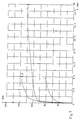
- the load-deformation lines of three dowels are plotted in the diagram according to FIG. Two of these lines, namely lines A and B, show the load-deformation behavior of conventional dowels. Both dowels have the same length and a constant cross-section over the entire length.
- the length corresponds to the total length of the dowel according to FIG. 1.
- the diameter corresponds to the diameter of the other shaft section 1 according to FIG. 1 for curve A and the diameter of section 2 of enlarged diameter according to FIG. 1 for curve B.
- the shear force F is in kN is plotted over the shear displacement s in mm.
- s represents the relative displacement of the steel component and thus also of the dowel foot compared to the concrete part.
- the breaking load for curve A and the associated dowel is approx. 80 kN and the breaking displacement approx. 7.5 mm, while for curve B and the associated bolt, the breaking load is approx. 155 kN and the breaking displacement is approx. 9.0 mm.
- Curve C comes from an experiment in which a dowel according to FIG. 1 was tested, the shaft diameter of which corresponds to that of the dowel according to curve A over approximately 80% of the dowel length and whose diameter in the section of increased diameter corresponded to that of the dowel according to curve B. It can be seen that the breaking load of around 140 kN is slightly lower than curve B, but there is a significant increase in the breaking displacement of around 29 mm.
- the load-bearing behavior and load-bearing capacity of a dowel according to the invention largely correspond to that of a conventional dowel with a constant diameter corresponding to the diameter of the other shaft section 1 when loaded under tension.
- the shear loads are often decisive for the design of the dowels, so that such an increased fracture displacement, the significantly increased work capacity and the high breaking loads in the shear direction are much more decisive.
- the major fracture displacements are e.g. of particular importance when using the load-bearing method in composite construction.
- Another advantage of the reduced diameter of the dowel according to FIG. 1 in the other shaft section is the fact that this leaves more space for the arrangement of reinforcing bars in the concrete. This is e.g. B. when using anchor plates, in their environment experience has shown that an accumulation of reinforcement is often necessary.
Landscapes
- Engineering & Computer Science (AREA)
- Architecture (AREA)
- Civil Engineering (AREA)
- Structural Engineering (AREA)
- Physics & Mathematics (AREA)
- Electromagnetism (AREA)
- Chemical & Material Sciences (AREA)
- Composite Materials (AREA)
- Joining Of Building Structures In Genera (AREA)
Claims (18)
- Elément de construction acier-béton comprenant une partie en acier et une partie en béton, reliées entre elles par au moins un goujon à souder en acier soudé sur la partie en acier, le goujon présentant une tige comportant une extrémité à souder (3), caractérisé en ce qu'un goujon est soudé dont la tige présente, en-deça de la soudure de l'extrémité à souder (3), un segment (2) de diamètre élargi par rapport à l'autre segment (1) de tige.
- Elément selon la revendication 1, caractérisé en ce que l'autre segment (1) de tige et le segment (2) de diamètre élargi sont conformés symétriques en rotation par rapport à un axe commun.
- Elément selon la revendication 1, caractérisé en ce que l'autre segment (1) de tige et le segment (2) de diamètre élargi sont de forme prismatique.
- Elément selon la revendication 1, caractérisé en ce que l'autre segment (1) de tige est symétrique en rotation et le segment (2) de diamètre élargi prismatique, ou en ce que l'autre segment (1) de tige est prismatique et le segment (2) de diamètre élargi est symétrique en rotation.
- Elément selon l'une quelconque des revendications 1, 2 ou 4, caractérisé en ce que l'autre segment (1) de tige et/ou le segment (2) de diamètre élargi présentent chacun la forme d'un cylindre circulaire droit.
- Elément selon l'une quelconque des revendications précédentes, caractérisé en ce que le segment (2) de diamètre élargi est convexe dans le sens de l'axe.
- Elément selon l'une quelconque des revendications précédentes, caractérisé en ce que le passage du segment (2) de diamètre élargi vers le segment se fait par un rétrécissement (4) progressif.
- Elément selon l'une quelconque des revendications 1 à 7, caractérisé en ce que le goujon présente à son extrémité libre une saillie (5).
- Elément selon l'une quelconque des revendications précédentes, caractérisé en ce que le diamètre de la saillie (5) est au moins de la dimension du diamètre du segment (2) de diamètre élargi.
- Elément selon l'une quelconque des revendications précédentes, caractérisé en ce que le rapport entre la longueur et le diamètre du segment (2) de diamètre élargi se situe entre 1/2 et 4/2.
- Elément selon la revendication 10, caractérisé en ce que le rapport de la longueur et du diamètre du segment (2) de diamètre élargi se situe entre 1/2 et 3/2.
- Elément selon l'une quelconque des revendications précédentes, caractérisé en ce que le rapport entre la longueur et le diamètre de l'autre segment (1) de tige est de l'ordre de 3/1 ou plus, saillie (5) non comprise.
- Elément selon l'une quelconque des revendications précédentes, caractérisé en ce que le rapport entre le diamètre du segment (2) de diamètre élargi et celui de l'autre segment (1) de tige se situe entre 7/6 et 10/6.
- Elément selon la revendication 13, caractérisé en ce que le rapport entre le diamètre du segment (2) de diamètre élargi et celui de l'autre segment (1) de tige est d'environ 9/6.
- Elément selon l'une quelconque des revendications précédentes, caractérisé en ce que le rapport entre la longueur du segment (2) de diamètre élargi et celle de l'autre segment (1) de tige est d'au moins 1/3, saillie (5) non comprise.
- Elément selon la revendication 15, caractérisé en ce que le rapport entre la longueur du segment (2) de diamètre élargi et celle de l'autre segment (1) de tige se situe entre 1/3 et 1/8, saillie (5) non comprise.
- Elément selon la revendication 16, caractérisé en ce que le rapport entre la longueur du segment (2) de diamètre élargi et celle de l'autre segment (1) de tige se situe entre 1/4 et 1/7, saillie (5) non comprise.
- Elément selon l'une quelconque des revendications précédentes, caractérisé en ce que le segment (2) de diamètre élargi présente une augmentation de section étagée.
Priority Applications (1)
| Application Number | Priority Date | Filing Date | Title |
|---|---|---|---|
| AT91111260T ATE102278T1 (de) | 1990-07-26 | 1991-07-06 | Stahl-beton-verbundbauteil. |
Applications Claiming Priority (3)
| Application Number | Priority Date | Filing Date | Title |
|---|---|---|---|
| DE4023692 | 1990-07-26 | ||
| DE4023692A DE4023692A1 (de) | 1990-07-26 | 1990-07-26 | Aufschweissduebel fuer den stahl/beton-verbundbau |
| SG129694A SG129694G (en) | 1990-07-26 | 1994-09-05 | Steel-concrete composite construction |
Publications (2)
| Publication Number | Publication Date |
|---|---|
| EP0469337A1 EP0469337A1 (fr) | 1992-02-05 |
| EP0469337B1 true EP0469337B1 (fr) | 1994-03-02 |
Family
ID=25895361
Family Applications (1)
| Application Number | Title | Priority Date | Filing Date |
|---|---|---|---|
| EP91111260A Expired - Lifetime EP0469337B1 (fr) | 1990-07-26 | 1991-07-06 | Construction composite acier-béton |
Country Status (6)
| Country | Link |
|---|---|
| US (1) | US5426903A (fr) |
| EP (1) | EP0469337B1 (fr) |
| JP (1) | JPH05156720A (fr) |
| AU (1) | AU8136391A (fr) |
| DE (2) | DE4023692A1 (fr) |
| SG (1) | SG129694G (fr) |
Families Citing this family (12)
| Publication number | Priority date | Publication date | Assignee | Title |
|---|---|---|---|---|
| DE4129903A1 (de) * | 1991-09-09 | 1993-03-11 | Deha Ankersysteme | Duebelleiste |
| DE4335166A1 (de) * | 1993-10-15 | 1995-04-20 | Eberhard Koch | Verbundelement |
| FR2760270B1 (fr) * | 1997-03-03 | 1999-05-14 | Dassault Electronique | Capteur de contraintes destine a etre noye dans un milieu deformable ou a prise tel que du beton |
| DE19859407C2 (de) * | 1998-12-22 | 2001-10-31 | Bauer Spezialtiefbau | Schlitzwandbewehrung für Ortbeton-Schlitzwände |
| ES2280852T3 (es) * | 2003-08-09 | 2007-09-16 | General Electric Company | Cimiento para torre, en particular para una turbina de energia eolica. |
| GB2414213B (en) * | 2004-05-21 | 2008-11-12 | Intelligent Engineering | Improved structural sandwich plate members |
| KR20070083474A (ko) * | 2004-08-18 | 2007-08-24 | 다이세이 겐세쓰 가부시키가이샤 | 전단력 보강 구조 및 전단력 보강부재 |
| US20070251169A1 (en) * | 2006-04-26 | 2007-11-01 | Dahl Kjell L | Grouted rebar dowel splice |
| WO2013005232A1 (fr) | 2011-07-05 | 2013-01-10 | Council Of Scientific & Industrial Research | Système composite lacé |
| CN106836650B (zh) * | 2017-03-28 | 2019-07-30 | 哈尔滨工业大学 | 一种抗剪钢筋 |
| CN106969975B (zh) * | 2017-03-28 | 2019-11-15 | 哈尔滨工业大学 | 一种抗剪栓钉 |
| JP7178895B2 (ja) * | 2018-12-20 | 2022-11-28 | 鹿島建設株式会社 | 主桁とプレキャスト床版との固定構造及び主桁とプレキャスト床版との固定方法 |
Family Cites Families (15)
| Publication number | Priority date | Publication date | Assignee | Title |
|---|---|---|---|---|
| US1662896A (en) * | 1925-03-05 | 1928-03-20 | George F Pawling | Attaching means for steel laths |
| US1956354A (en) * | 1928-03-07 | 1934-04-24 | Junkers Hugo | Structural element |
| US1837793A (en) * | 1929-09-07 | 1931-12-22 | Randall Company | Method of making upholstery |
| US2040365A (en) * | 1932-12-23 | 1936-05-12 | Detroit Gasket & Mfg Co | Upholstery installation and method of making same |
| US2367657A (en) * | 1941-01-17 | 1945-01-23 | Duffy Mfg Company | Attaching device |
| US2537466A (en) * | 1946-09-12 | 1951-01-09 | Allegheny Ludlum Steel | Lining for vessels |
| US2623508A (en) * | 1948-09-10 | 1952-12-30 | Tross Arnold | Locomotive firebox and bracing means therefor |
| US2987855A (en) * | 1958-07-18 | 1961-06-13 | Gregory Ind Inc | Composite tall-beam |
| DE1087996B (de) * | 1959-02-12 | 1960-09-01 | Beteiligungs & Patentverw Gmbh | Schachtauskleidung |
| CH410343A (de) * | 1961-10-23 | 1966-03-31 | Crompton Parkinson Ltd | Verbundbau-Konstruktion |
| US4226068A (en) * | 1978-12-04 | 1980-10-07 | Fern Engineering | Appearance system |
| US4445303A (en) * | 1982-04-26 | 1984-05-01 | Judkins Milton W | Wedge-type concrete insert |
| US4741138A (en) * | 1984-03-05 | 1988-05-03 | Rongoe Jr James | Girder system |
| DE3419315A1 (de) * | 1984-04-14 | 1985-10-24 | Leonhardt, Fritz, Prof. Dr.-Ing., 7000 Stuttgart | Verbundmittel fuer stahl-verbundkonstruktionen |
| DE3507197A1 (de) * | 1985-03-01 | 1986-09-04 | Wolfhart Dr.-Ing. 7000 Stuttgart Andrä | Verbundmittel fuer stahl-beton-verbundkonstruktionen |
-
1990
- 1990-07-26 DE DE4023692A patent/DE4023692A1/de not_active Withdrawn
-
1991
- 1991-07-06 DE DE91111260T patent/DE59101075D1/de not_active Expired - Fee Related
- 1991-07-06 EP EP91111260A patent/EP0469337B1/fr not_active Expired - Lifetime
- 1991-07-25 AU AU81363/91A patent/AU8136391A/en not_active Abandoned
- 1991-07-26 JP JP3187170A patent/JPH05156720A/ja active Pending
-
1993
- 1993-09-03 US US08/115,597 patent/US5426903A/en not_active Expired - Fee Related
-
1994
- 1994-09-05 SG SG129694A patent/SG129694G/en unknown
Also Published As
| Publication number | Publication date |
|---|---|
| SG129694G (en) | 1995-03-17 |
| DE59101075D1 (de) | 1994-04-07 |
| JPH05156720A (ja) | 1993-06-22 |
| EP0469337A1 (fr) | 1992-02-05 |
| DE4023692A1 (de) | 1992-01-30 |
| US5426903A (en) | 1995-06-27 |
| AU8136391A (en) | 1992-01-30 |
Similar Documents
| Publication | Publication Date | Title |
|---|---|---|
| DE3877739T2 (de) | Verfahren zur realisierung von mechanischen betonstahlverbindungen, betonstahlverbindung fuer ein solches verfahren, und entsprechend erzielte mechanische betonstahlverbindung. | |
| EP0469337B1 (fr) | Construction composite acier-béton | |
| DE60019749T2 (de) | Betonstruktur mit ankerstäben und ankerstab | |
| DE69410077T2 (de) | Vorgefertigter stahlbetonverbundträger | |
| DE102004026871A1 (de) | Verbundträger aus hochfesten Werkstoffen mit Gestaltungsmerkmalen, die eine Ausschöpfung beliebig unterschiedlicher Dehnungs- und Festigkeitspotenziale der Werkstoffe in einem Trägerquerschnitt sicherstellen | |
| DE102009013241B4 (de) | Aus einem einstückigen Stahlbauprofil bestehender Träger | |
| DE69808495T2 (de) | Betonbewehrungsfaser | |
| EP2372036A1 (fr) | Dispositif d'ancrage d'une barre de mise en tension | |
| EP0189443B1 (fr) | Tirant d'ancrage et pieu precontraints | |
| EP0988430B1 (fr) | Panne de couplage constituee de deux ou plusieurs poutres en bois jointes l'une a l'autre par chevauchement longitudinal, ainsi qu'element de fixation pour relier deux zones d'extremite se chevauchant de poutres en bois a utiliser pour une panne de couplage | |
| EP3819431B1 (fr) | Agencement de renfort au moyen d'une construction existante et d'un dispositif de renfort appliqué à celle-ci ainsi que procédé de renforcement d'une construction existante | |
| DE3131078C1 (de) | "Verankerungs- oder Verbindungskörper für Stahlstäbe mit Oberflächenprofilierungen in Form von Rippen" | |
| DE202005019077U1 (de) | Bewehrungselement für Tragwerke aus Stahlbeton, Spannbeton od.dgl. | |
| EP4339383B1 (fr) | Dispositif de liaison pour la liaison de transmission de force d'une première partie de construction absorbant de force à une seconde partie de construction absorbant de force et construction | |
| EP0284609B1 (fr) | Element de construction en forme de support | |
| EP0796961B1 (fr) | Bétoncellulaire avec système d'armatures | |
| DE102019129354A1 (de) | Mit wenigstens einem Spannglied vorgespanntes Bauwerk sowie Verfahren zur Herstellung eines mit wenigstens einem Spannglied vorgespannten Bauwerks | |
| DE7525732U (de) | Verbundtraeger | |
| AT521549B1 (de) | Verfahren zur Herstellung einer Verankerung für ein Zugglied in einer Betonplatte | |
| AT411699B (de) | Bauwerk mit wandungen, die mit beton aufgebaut sind und schalung für ein bauwerk | |
| DE4131214A1 (de) | Brueckenkonstruktion und verfahren zum herstellen einer bruecke | |
| AT335703B (de) | Schubanker fur verbundtrager | |
| DE2261473A1 (de) | Armiereinrichtung fuer spannbetonelemente | |
| WO1980001818A1 (fr) | Armature pour beton arme et procede pour sa fabrication | |
| DE4039335C2 (de) | Walzprofil für Verbundträger |
Legal Events
| Date | Code | Title | Description |
|---|---|---|---|
| PUAI | Public reference made under article 153(3) epc to a published international application that has entered the european phase |
Free format text: ORIGINAL CODE: 0009012 |
|
| AK | Designated contracting states |
Kind code of ref document: A1 Designated state(s): AT BE CH DE DK ES FR GB IT LI LU NL SE |
|
| 17P | Request for examination filed |
Effective date: 19920214 |
|
| 17Q | First examination report despatched |
Effective date: 19920722 |
|
| GRAA | (expected) grant |
Free format text: ORIGINAL CODE: 0009210 |
|
| AK | Designated contracting states |
Kind code of ref document: B1 Designated state(s): AT BE CH DE DK ES FR GB IT LI LU NL SE |
|
| PG25 | Lapsed in a contracting state [announced via postgrant information from national office to epo] |
Ref country code: NL Effective date: 19940302 Ref country code: ES Free format text: THE PATENT HAS BEEN ANNULLED BY A DECISION OF A NATIONAL AUTHORITY Effective date: 19940302 Ref country code: DK Effective date: 19940302 |
|
| REF | Corresponds to: |
Ref document number: 102278 Country of ref document: AT Date of ref document: 19940315 Kind code of ref document: T |
|
| REF | Corresponds to: |
Ref document number: 59101075 Country of ref document: DE Date of ref document: 19940407 |
|
| GBT | Gb: translation of ep patent filed (gb section 77(6)(a)/1977) |
Effective date: 19940415 |
|
| ITF | It: translation for a ep patent filed | ||
| ET | Fr: translation filed | ||
| PG25 | Lapsed in a contracting state [announced via postgrant information from national office to epo] |
Ref country code: LU Free format text: LAPSE BECAUSE OF NON-PAYMENT OF DUE FEES Effective date: 19940731 |
|
| NLV1 | Nl: lapsed or annulled due to failure to fulfill the requirements of art. 29p and 29m of the patents act | ||
| PLBE | No opposition filed within time limit |
Free format text: ORIGINAL CODE: 0009261 |
|
| STAA | Information on the status of an ep patent application or granted ep patent |
Free format text: STATUS: NO OPPOSITION FILED WITHIN TIME LIMIT |
|
| EAL | Se: european patent in force in sweden |
Ref document number: 91111260.5 |
|
| 26N | No opposition filed | ||
| PGFP | Annual fee paid to national office [announced via postgrant information from national office to epo] |
Ref country code: AT Payment date: 19950714 Year of fee payment: 5 |
|
| PGFP | Annual fee paid to national office [announced via postgrant information from national office to epo] |
Ref country code: SE Payment date: 19950717 Year of fee payment: 5 |
|
| PGFP | Annual fee paid to national office [announced via postgrant information from national office to epo] |
Ref country code: BE Payment date: 19950718 Year of fee payment: 5 |
|
| PGFP | Annual fee paid to national office [announced via postgrant information from national office to epo] |
Ref country code: CH Payment date: 19950927 Year of fee payment: 5 |
|
| PGFP | Annual fee paid to national office [announced via postgrant information from national office to epo] |
Ref country code: GB Payment date: 19960704 Year of fee payment: 6 |
|
| PG25 | Lapsed in a contracting state [announced via postgrant information from national office to epo] |
Ref country code: AT Effective date: 19960706 |
|
| PG25 | Lapsed in a contracting state [announced via postgrant information from national office to epo] |
Ref country code: SE Effective date: 19960707 |
|
| PGFP | Annual fee paid to national office [announced via postgrant information from national office to epo] |
Ref country code: DE Payment date: 19960718 Year of fee payment: 6 |
|
| PG25 | Lapsed in a contracting state [announced via postgrant information from national office to epo] |
Ref country code: LI Effective date: 19960731 Ref country code: CH Effective date: 19960731 Ref country code: BE Effective date: 19960731 |
|
| PGFP | Annual fee paid to national office [announced via postgrant information from national office to epo] |
Ref country code: FR Payment date: 19960731 Year of fee payment: 6 |
|
| BERE | Be: lapsed |
Owner name: SCHEELE JOACHIM Effective date: 19960731 Owner name: RAMM WIELAND Effective date: 19960731 |
|
| REG | Reference to a national code |
Ref country code: CH Ref legal event code: PL |
|
| EUG | Se: european patent has lapsed |
Ref document number: 91111260.5 |
|
| PG25 | Lapsed in a contracting state [announced via postgrant information from national office to epo] |
Ref country code: GB Free format text: LAPSE BECAUSE OF NON-PAYMENT OF DUE FEES Effective date: 19970706 |
|
| GBPC | Gb: european patent ceased through non-payment of renewal fee |
Effective date: 19970706 |
|
| PG25 | Lapsed in a contracting state [announced via postgrant information from national office to epo] |
Ref country code: FR Free format text: LAPSE BECAUSE OF NON-PAYMENT OF DUE FEES Effective date: 19980331 |
|
| PG25 | Lapsed in a contracting state [announced via postgrant information from national office to epo] |
Ref country code: DE Free format text: LAPSE BECAUSE OF NON-PAYMENT OF DUE FEES Effective date: 19980401 |
|
| REG | Reference to a national code |
Ref country code: FR Ref legal event code: ST |
|
| PG25 | Lapsed in a contracting state [announced via postgrant information from national office to epo] |
Ref country code: IT Free format text: LAPSE BECAUSE OF NON-PAYMENT OF DUE FEES;WARNING: LAPSES OF ITALIAN PATENTS WITH EFFECTIVE DATE BEFORE 2007 MAY HAVE OCCURRED AT ANY TIME BEFORE 2007. THE CORRECT EFFECTIVE DATE MAY BE DIFFERENT FROM THE ONE RECORDED. Effective date: 20050706 |