EP0469414A2 - Méthode pour mesurer un outil dans une machine-outil à commande numérique avec changeur d'outils automatique et système pour ceci - Google Patents
Méthode pour mesurer un outil dans une machine-outil à commande numérique avec changeur d'outils automatique et système pour ceci Download PDFInfo
- Publication number
- EP0469414A2 EP0469414A2 EP91112163A EP91112163A EP0469414A2 EP 0469414 A2 EP0469414 A2 EP 0469414A2 EP 91112163 A EP91112163 A EP 91112163A EP 91112163 A EP91112163 A EP 91112163A EP 0469414 A2 EP0469414 A2 EP 0469414A2
- Authority
- EP
- European Patent Office
- Prior art keywords
- measuring
- measuring beam
- tool
- spindle head
- tools
- Prior art date
- Legal status (The legal status is an assumption and is not a legal conclusion. Google has not performed a legal analysis and makes no representation as to the accuracy of the status listed.)
- Granted
Links
Images

Classifications
-
- G—PHYSICS
- G05—CONTROLLING; REGULATING
- G05B—CONTROL OR REGULATING SYSTEMS IN GENERAL; FUNCTIONAL ELEMENTS OF SUCH SYSTEMS; MONITORING OR TESTING ARRANGEMENTS FOR SUCH SYSTEMS OR ELEMENTS
- G05B19/00—Program-control systems
- G05B19/02—Program-control systems electric
- G05B19/18—Numerical control [NC], i.e. automatically operating machines, in particular machine tools, e.g. in a manufacturing environment, so as to execute positioning, movement or co-ordinated operations by means of program data in numerical form
- G05B19/406—Numerical control [NC], i.e. automatically operating machines, in particular machine tools, e.g. in a manufacturing environment, so as to execute positioning, movement or co-ordinated operations by means of program data in numerical form characterised by monitoring or safety
- G05B19/4065—Monitoring tool breakage, life or condition
Definitions
- the invention relates to a method for measuring a tool in a numerically controlled processing machine with automatic tool change according to the preamble of claim 1 and a device for carrying out such a method according to the preamble of claim 4.
- the most frequently required multi-spindle heads are designed so that two tools are located one behind the other in a common plane.
- a tool is therefore usually covered by the one in front of it, so that the measuring beam cannot detect the tool behind it.
- the invention has for its object to design the generic method and the generic device so that both individual tools and all tools of a multi-spindle head can be measured on a processing machine in a simple manner.
- the measuring beam is directed at an angle to the X-Y coordinate system of the processing machine.
- all tools of the most common multi-spindle heads can be detected and measured with just a single measuring beam.
- the multi-spindle head is hereby moved in a controlled manner in relation to the stationary measuring beam in the desired direction, so that the individual tools of the multi-spindle head successively get into the measuring beam. Even if two tools of the multi-spindle head lie one behind the other in a common horizontal or vertical plane, each tool is detected due to the position of the measuring beam inclined to the X-Y coordinate system.
- each tool of the most common multi-spindle heads can be checked and checked in a very simple and constructive manner before or after the tool is used. If a tool has wear, then it no longer protrudes into the measuring beam in the respectively predetermined measuring position of the multi-spindle head, so that this is no longer interrupted by the tool.
- the measuring beam falling on the receiver generates a corresponding measuring signal.
- This single measuring beam can also be used to check whether the correct tool has been inserted in terms of its length.
- the measuring position of the multi-spindle head is preprogrammed and matched to the correct tool length.
- the measuring method and the measuring device it is possible to detect several tools on a multi-spindle head with only a single measuring beam. With the measuring device it is possible to check for breakage of each tool. It can also be determined whether the tools with the correct length are present in the multi-spindle head.
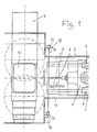
- the processing machine shown in FIGS. 1 and 2 has a stand 1, which on a Machine bed 2 can be moved along guides 3 in the Z direction.
- the stand 1 is provided on its front side with vertical guides 4, along which a carriage unit 5 can be moved vertically in the Y direction.
- the carriage unit 5 has a work spindle 6, with which a tool 7 can be rotatably driven.
- the carriage unit 5 is designed such that, in addition to individual tools, multi-spindle heads 8 and 8a (FIGS. 3 and 4) can be connected to it. 1 and 2 only a single tool is shown in order to be able to clearly describe the measuring principle.
- a work table 10 which can be, for example, an indexing table or a rotary table, can be adjusted horizontally in the X direction perpendicular to the guides 3.
- the workpiece to be machined with the tool 7 is clamped on the work table 10 in a known manner.
- the processing machine described is a CNC machine in which the stand 1 with the slide unit 5 can be moved horizontally against the workpiece in the Z direction.
- the carriage unit 5 itself can be moved perpendicularly to this in the height direction (Y direction), while the work table 10 with the clamped workpiece can be adjusted perpendicular to the Z direction in the X direction.
- the processing machine is partially covered by a covering 11.
- the processing machine is equipped with a measuring device 12 which has a transmitter 13 and a receiver 14.
- the receiver 14 collects the measuring beam 15 emitted by the transmitter 13.
- the receiver 14 is connected to an evaluation circuit 16, to which the receiver 14 emits a corresponding signal.
- any conventional transmitter which emits a measuring beam for example a light beam, an infrared beam, a laser beam or the like, can be used as the transmitter 13.
- the receiver 14 is matched to the measuring beam 15 used in each case.
- Such measuring devices 12 are known per se.
- the slide unit 5 is set in the Y direction to the height corresponding to the tool 7 to be tested, so that the tool axis and the measuring beam axis intersect. Then the stand 1 is moved in the Z direction to the tool length test position (measuring position). This process is repeated for each tool 7 of a multi-spindle head. The stand 1 and / or the slide unit 5, depending on the tool 7 used, are automatically moved under computer control into the required measuring position. If the tool 7 is not damaged and / or the correct tool has been inserted, the tip of the tool 7 interrupts the measuring beam 15 in the programmed measuring position, so that no measuring beam falls on the receiver 14.
- the tool 7 If the tool 7 is damaged or a tool that is too short has been replaced in the processing machine, then the tool does not interrupt the measuring beam 15 in the predetermined measuring position of the stand 1 and / or the slide unit 5, so that it falls on the receiver 14. It then emits a corresponding signal to the evaluation circuit 16. It can then, for example, generate an interference signal or automatically initiate a replacement process for this tool with a corresponding output signal or switch off the processing machine.
- the measuring beam 15 is interrupted by the tool 7 even before the programmed measuring position is submitted and is thus recognized by the measuring device 12.
- the measuring beam 15 is provided at an angle ⁇ to the XY coordinate system of the processing machine, in the exemplary embodiment shown to the horizontal 17.
- the acute angle a is advantageously not equal to 45 ° or 30 °.
- the measuring beam 15 can capture all the tools 7 of the work spindle head 8.
- a total of six measuring beams 15 are shown in FIG. 3 for clarification; in fact the measuring device 12 is at a standstill; only the slide unit 5 is adjusted so that all the tools 7 successively get into the measuring beam 15 each time the stand 1 is ancestor. Since the measuring angle a is not equal to 30 ° or 45, this multi-spindle head 8 ensures that all tools 7 can be detected by the measuring beam 15, although two tools 7 are always arranged one behind the other in common planes. In the hexagonal arrangement of the tools 7 according to FIG. 3, two tools each lie in two horizontal planes lying parallel to one another or in three vertical planes lying parallel to one another or in three oblique planes crossing one another.
- the processing machine is programmed in such a way that the required measuring positions for the six tools 7 are automatically approached after the multi-spindle head 8 has been replaced or after processing. If one of the tools 7 damaged or a wrong tool, it does not interrupt the measuring beam 15 or too early, so that the receiver 14 gives a corresponding signal to the evaluation circuit 16. In this way, not only a single tool, but also a multitude of tools of a multi-spindle head can be checked reliably with only one measuring device with only one measuring beam.
- each tool 7 can be checked with the single measuring beam 15.
- the measurement beam 15 again runs at an acute angle a to the horizontal line 17 and is advantageously equal to 30 0 and / or 45 °.
- each tool 7 of the multi-spindle head 8a can again be detected and checked with the single measuring beam 15.
- the processing machine is programmed such that the required measuring positions for the tools 7 are automatically approached after the multi-spindle head 8a has been replaced and / or after each processing operation.
- the angle a is selected so that the common multi-spindle heads can be checked with only a single measuring beam 15. Therefore, no additional measuring devices are required, so that the processing machine equipped with such a measuring device 12 has a simple structure and is inexpensive to purchase. Since the multi-spindle head 8, 8a can be moved in the Y and Z directions via the stand 1 and the slide unit 5, the measuring device 12 can be provided in a fixed position next to the machine or also on the machine. As a result of the measuring beam 15 running obliquely to the horizontal, it is also possible to check multi-spindle heads which have a different number of spindles than the multi-spindle heads shown by way of example in FIGS. 3 and 4.
- the tools can be checked easily before each delivery of the corresponding tool to the workpiece, but also after a machining operation.
Landscapes
- Engineering & Computer Science (AREA)
- Human Computer Interaction (AREA)
- Manufacturing & Machinery (AREA)
- Physics & Mathematics (AREA)
- General Physics & Mathematics (AREA)
- Automation & Control Theory (AREA)
- Machine Tool Sensing Apparatuses (AREA)
- Automatic Tool Replacement In Machine Tools (AREA)
- Automatic Control Of Machine Tools (AREA)
Applications Claiming Priority (2)
| Application Number | Priority Date | Filing Date | Title |
|---|---|---|---|
| DE4023581A DE4023581A1 (de) | 1990-07-25 | 1990-07-25 | Verfahren zum vermessen eines werkzeuges in einer numerisch gesteuerten bearbeitungsmaschine mit automatischem werkzeugwechsel und einrichtung zur durchfuehrung dieses verfahrens |
| DE4023581 | 1990-07-25 |
Publications (3)
| Publication Number | Publication Date |
|---|---|
| EP0469414A2 true EP0469414A2 (fr) | 1992-02-05 |
| EP0469414A3 EP0469414A3 (en) | 1992-03-04 |
| EP0469414B1 EP0469414B1 (fr) | 1996-03-20 |
Family
ID=6410967
Family Applications (1)
| Application Number | Title | Priority Date | Filing Date |
|---|---|---|---|
| EP91112163A Expired - Lifetime EP0469414B1 (fr) | 1990-07-25 | 1991-07-20 | Méthode pour mesurer un outil dans une machine-outil à commande numérique avec changeur d'outils automatique et système pour ceci |
Country Status (3)
| Country | Link |
|---|---|
| EP (1) | EP0469414B1 (fr) |
| AT (1) | ATE135830T1 (fr) |
| DE (2) | DE4023581A1 (fr) |
Cited By (4)
| Publication number | Priority date | Publication date | Assignee | Title |
|---|---|---|---|---|
| DE19607599A1 (de) * | 1996-02-29 | 1997-09-04 | Hueller Hille Gmbh | Verfahren zur Korrektur der Positionsbestimmung von Werkstücken und Werkzeugen in Bearbeitungsmaschinen |
| EP1745884A1 (fr) * | 2005-07-21 | 2007-01-24 | Cross Hüller GmbH | Procédé pour détecter un débattement ou un déséquilibre d'un outil |
| CN111604710A (zh) * | 2020-04-30 | 2020-09-01 | 南京理工大学 | 一种自动换刀装置输出轴运动精度检测装置和方法 |
| US11840650B2 (en) | 2017-09-01 | 2023-12-12 | Dic Corporation | Black sheet and black adhesive tape |
Family Cites Families (4)
| Publication number | Priority date | Publication date | Assignee | Title |
|---|---|---|---|---|
| US2677168A (en) * | 1950-04-04 | 1954-05-04 | Milton H Feig | Control device for automatic machinery |
| US4228514A (en) * | 1979-04-16 | 1980-10-14 | Bell Telephone Laboratories, Incorporated | Method and system for determining the wear of a drill bit in real time |
| DE3218754C2 (de) * | 1982-05-18 | 1985-11-28 | Friedrich Deckel AG, 8000 München | Verfahren und Einrichtung zur Vermessung eines in einem zustellbaren Werkzeughalter einer Werkzeugmaschine eingespannten Werkzeugs |
| DE3501533A1 (de) * | 1985-01-18 | 1986-07-24 | K.A. Schmersal Gmbh & Co, 5600 Wuppertal | Verfahren und vorrichtung zur werkzeugbruchueberwachung |
-
1990
- 1990-07-25 DE DE4023581A patent/DE4023581A1/de active Granted
-
1991
- 1991-07-20 DE DE59107568T patent/DE59107568D1/de not_active Expired - Fee Related
- 1991-07-20 EP EP91112163A patent/EP0469414B1/fr not_active Expired - Lifetime
- 1991-07-20 AT AT91112163T patent/ATE135830T1/de not_active IP Right Cessation
Cited By (6)
| Publication number | Priority date | Publication date | Assignee | Title |
|---|---|---|---|---|
| DE19607599A1 (de) * | 1996-02-29 | 1997-09-04 | Hueller Hille Gmbh | Verfahren zur Korrektur der Positionsbestimmung von Werkstücken und Werkzeugen in Bearbeitungsmaschinen |
| EP1745884A1 (fr) * | 2005-07-21 | 2007-01-24 | Cross Hüller GmbH | Procédé pour détecter un débattement ou un déséquilibre d'un outil |
| US7217071B2 (en) | 2005-07-21 | 2007-05-15 | Cross Huller Gmbh | Method for testing the fit or imbalance of a tool |
| US11840650B2 (en) | 2017-09-01 | 2023-12-12 | Dic Corporation | Black sheet and black adhesive tape |
| CN111604710A (zh) * | 2020-04-30 | 2020-09-01 | 南京理工大学 | 一种自动换刀装置输出轴运动精度检测装置和方法 |
| CN111604710B (zh) * | 2020-04-30 | 2022-06-07 | 南京理工大学 | 一种自动换刀装置输出轴运动精度检测装置和方法 |
Also Published As
| Publication number | Publication date |
|---|---|
| EP0469414B1 (fr) | 1996-03-20 |
| ATE135830T1 (de) | 1996-04-15 |
| DE59107568D1 (de) | 1996-04-25 |
| DE4023581C2 (fr) | 1992-08-27 |
| DE4023581A1 (de) | 1992-02-13 |
| EP0469414A3 (en) | 1992-03-04 |
Similar Documents
| Publication | Publication Date | Title |
|---|---|---|
| DE69200382T2 (de) | Numerisch gesteuerte Schleifmaschine. | |
| DE3126276C2 (fr) | ||
| DE69217977T2 (de) | Vorrichtung zur feststellung der wirksamkeit eines maschinenwerkzeugs | |
| DE4244869C2 (de) | Verfahren zum Vermessen eines Werkzeuges | |
| DE3218754C2 (de) | Verfahren und Einrichtung zur Vermessung eines in einem zustellbaren Werkzeughalter einer Werkzeugmaschine eingespannten Werkzeugs | |
| DE4033520A1 (de) | Mehrspindelmaschine zum bohren, fraesen oder dergleichen | |
| DE69230376T2 (de) | Verfahren und gerät zum sichern der korrekten bearbeitung einer folie | |
| EP0505787A2 (fr) | Dispositif pour l'ajustage d'une rectifieuse à commande CNC | |
| DE1945017B2 (de) | Vorrichtung zum einstellen des arbeitspunktes eines in einem werkzeugtraeger befestigten werkzeuges | |
| EP0789221A2 (fr) | Méthode pour mesurer les coordonnées de pièces usinées sur des machines-outils | |
| DE4411263C2 (de) | Verfahren zur Überprüfung der Führungsgenauigkeit einer Brennschneidmaschine und Anordnung zur Durchführung des Verfahrens | |
| EP0403908A2 (fr) | Procédé et dispositif pour mesurer les contours d'un objet | |
| DE9103229U1 (de) | Meß- und Verarbeitungsstation für große Werkstücke | |
| DE102009024752A1 (de) | Verfahren zum Vermessen und/oder Kalibrieren einer numerisch gesteuerten Werkzeugmaschine | |
| EP0469414B1 (fr) | Méthode pour mesurer un outil dans une machine-outil à commande numérique avec changeur d'outils automatique et système pour ceci | |
| DE102020203770A1 (de) | Steuergerät und Werkzeugmaschine | |
| DE3331393A1 (de) | Verfahren zur bestimmung der lage des mittelpunktes eines kreisfoermigen gegenstandes | |
| EP0127751A1 (fr) | Système de contrôle d'outils brisés | |
| DE2941156C2 (de) | Verfahren zum Ermitteln der Lage einer Werkzeugspitze in bezug auf einen Werkzeugschlitten einer numerisch gesteuerten Werkzeugmaschine, insbesondere Drehmaschine | |
| DE19819332A1 (de) | Plattenbearbeitungsmaschine und Verfahren zur Bearbeitung von Platten | |
| DE3445254C2 (fr) | ||
| DE19609511A1 (de) | Hilfsvorrichtung für handgeführte Werkzeuge | |
| EP0326625A1 (fr) | Appareil pour déterminer les irrégularités d'une machine d'usinage de pièces | |
| DE102020105871B4 (de) | Drehtischmodul und koordinatenmessgerät mit drehtischmodul und verfahren zum betrieb derselben | |
| DE2502203A1 (de) | Automatisches werkzeugkorrektursystem |
Legal Events
| Date | Code | Title | Description |
|---|---|---|---|
| PUAI | Public reference made under article 153(3) epc to a published international application that has entered the european phase |
Free format text: ORIGINAL CODE: 0009012 |
|
| PUAL | Search report despatched |
Free format text: ORIGINAL CODE: 0009013 |
|
| AK | Designated contracting states |
Kind code of ref document: A2 Designated state(s): AT CH DE FR GB IT LI |
|
| AK | Designated contracting states |
Kind code of ref document: A3 Designated state(s): AT CH DE FR GB IT LI |
|
| 17P | Request for examination filed |
Effective date: 19920825 |
|
| 17Q | First examination report despatched |
Effective date: 19940628 |
|
| GRAH | Despatch of communication of intention to grant a patent |
Free format text: ORIGINAL CODE: EPIDOS IGRA |
|
| GRAA | (expected) grant |
Free format text: ORIGINAL CODE: 0009210 |
|
| AK | Designated contracting states |
Kind code of ref document: B1 Designated state(s): AT CH DE FR GB IT LI |
|
| REF | Corresponds to: |
Ref document number: 135830 Country of ref document: AT Date of ref document: 19960415 Kind code of ref document: T |
|
| REF | Corresponds to: |
Ref document number: 59107568 Country of ref document: DE Date of ref document: 19960425 |
|
| GBT | Gb: translation of ep patent filed (gb section 77(6)(a)/1977) |
Effective date: 19960403 |
|
| ITF | It: translation for a ep patent filed | ||
| PGFP | Annual fee paid to national office [announced via postgrant information from national office to epo] |
Ref country code: FR Payment date: 19960626 Year of fee payment: 6 |
|
| ET | Fr: translation filed | ||
| PG25 | Lapsed in a contracting state [announced via postgrant information from national office to epo] |
Ref country code: GB Effective date: 19960720 Ref country code: AT Effective date: 19960720 |
|
| PG25 | Lapsed in a contracting state [announced via postgrant information from national office to epo] |
Ref country code: LI Effective date: 19960731 Ref country code: CH Effective date: 19960731 |
|
| PLBE | No opposition filed within time limit |
Free format text: ORIGINAL CODE: 0009261 |
|
| STAA | Information on the status of an ep patent application or granted ep patent |
Free format text: STATUS: NO OPPOSITION FILED WITHIN TIME LIMIT |
|
| 26N | No opposition filed | ||
| GBPC | Gb: european patent ceased through non-payment of renewal fee |
Effective date: 19960720 |
|
| REG | Reference to a national code |
Ref country code: CH Ref legal event code: PL |
|
| PG25 | Lapsed in a contracting state [announced via postgrant information from national office to epo] |
Ref country code: FR Free format text: LAPSE BECAUSE OF NON-PAYMENT OF DUE FEES Effective date: 19980331 |
|
| REG | Reference to a national code |
Ref country code: FR Ref legal event code: ST |
|
| PGFP | Annual fee paid to national office [announced via postgrant information from national office to epo] |
Ref country code: DE Payment date: 20040927 Year of fee payment: 14 |
|
| PG25 | Lapsed in a contracting state [announced via postgrant information from national office to epo] |
Ref country code: IT Free format text: LAPSE BECAUSE OF NON-PAYMENT OF DUE FEES;WARNING: LAPSES OF ITALIAN PATENTS WITH EFFECTIVE DATE BEFORE 2007 MAY HAVE OCCURRED AT ANY TIME BEFORE 2007. THE CORRECT EFFECTIVE DATE MAY BE DIFFERENT FROM THE ONE RECORDED. Effective date: 20050720 |
|
| PG25 | Lapsed in a contracting state [announced via postgrant information from national office to epo] |
Ref country code: DE Free format text: LAPSE BECAUSE OF NON-PAYMENT OF DUE FEES Effective date: 20060201 |