EP0469530A1 - Dispositif de bobine d'allumage couplé directement à bougie d'allumage pour moteur à combustion interne - Google Patents
Dispositif de bobine d'allumage couplé directement à bougie d'allumage pour moteur à combustion interne Download PDFInfo
- Publication number
- EP0469530A1 EP0469530A1 EP91112748A EP91112748A EP0469530A1 EP 0469530 A1 EP0469530 A1 EP 0469530A1 EP 91112748 A EP91112748 A EP 91112748A EP 91112748 A EP91112748 A EP 91112748A EP 0469530 A1 EP0469530 A1 EP 0469530A1
- Authority
- EP
- European Patent Office
- Prior art keywords
- wire rods
- iron core
- ignition coil
- coil assembly
- central iron
- Prior art date
- Legal status (The legal status is an assumption and is not a legal conclusion. Google has not performed a legal analysis and makes no representation as to the accuracy of the status listed.)
- Granted
Links
Images




Classifications
-
- H—ELECTRICITY
- H01—ELECTRIC ELEMENTS
- H01F—MAGNETS; INDUCTANCES; TRANSFORMERS; SELECTION OF MATERIALS FOR THEIR MAGNETIC PROPERTIES
- H01F3/00—Cores, Yokes, or armatures
- H01F3/06—Cores, Yokes, or armatures made from wires
-
- F—MECHANICAL ENGINEERING; LIGHTING; HEATING; WEAPONS; BLASTING
- F02—COMBUSTION ENGINES; HOT-GAS OR COMBUSTION-PRODUCT ENGINE PLANTS
- F02P—IGNITION, OTHER THAN COMPRESSION IGNITION, FOR INTERNAL-COMBUSTION ENGINES; TESTING OF IGNITION TIMING IN COMPRESSION-IGNITION ENGINES
- F02P13/00—Sparking plugs structurally combined with other parts of internal-combustion engines
-
- H—ELECTRICITY
- H01—ELECTRIC ELEMENTS
- H01F—MAGNETS; INDUCTANCES; TRANSFORMERS; SELECTION OF MATERIALS FOR THEIR MAGNETIC PROPERTIES
- H01F38/00—Adaptations of transformers or inductances for specific applications or functions
- H01F38/12—Ignition, e.g. for IC engines
-
- H—ELECTRICITY
- H01—ELECTRIC ELEMENTS
- H01F—MAGNETS; INDUCTANCES; TRANSFORMERS; SELECTION OF MATERIALS FOR THEIR MAGNETIC PROPERTIES
- H01F41/00—Apparatus or processes specially adapted for manufacturing or assembling magnets, inductances or transformers; Apparatus or processes specially adapted for manufacturing materials characterised by their magnetic properties
- H01F41/02—Apparatus or processes specially adapted for manufacturing or assembling magnets, inductances or transformers; Apparatus or processes specially adapted for manufacturing materials characterised by their magnetic properties for manufacturing cores, coils, or magnets
- H01F41/0206—Manufacturing of magnetic cores by mechanical means
-
- Y—GENERAL TAGGING OF NEW TECHNOLOGICAL DEVELOPMENTS; GENERAL TAGGING OF CROSS-SECTIONAL TECHNOLOGIES SPANNING OVER SEVERAL SECTIONS OF THE IPC; TECHNICAL SUBJECTS COVERED BY FORMER USPC CROSS-REFERENCE ART COLLECTIONS [XRACs] AND DIGESTS
- Y10—TECHNICAL SUBJECTS COVERED BY FORMER USPC
- Y10T—TECHNICAL SUBJECTS COVERED BY FORMER US CLASSIFICATION
- Y10T29/00—Metal working
- Y10T29/49—Method of mechanical manufacture
- Y10T29/49002—Electrical device making
- Y10T29/4902—Electromagnet, transformer or inductor
- Y10T29/49075—Electromagnet, transformer or inductor including permanent magnet or core
- Y10T29/49078—Laminated
Definitions
- the present invention relates principally to an ignition coil assembly to be arranged to be directly coupled to an ignition plug for internal combustion engines.
- Such types of ignition coil assemblies generally comprise a central iron core constructed by placing silicon steel plates one upon another so as to form the outer shape to a square pole configuration such as is disclosed in the Japanese Patent Provisional Publication No. 63-132411.
- a problem which arises with the aforementioned conventional ignition coil assembly comprising the central iron core with a square pole configuration, however, in that difficulty can particularly be encountered to encase it in a space such as a cylindrical plug hole for insertion of the ignition plug.
- an ignition coil assembly for an internal combustion engine comprising a central iron core formed by bundling magnetic wire rods to have a cylindrical configuration and processing them under a pressure, and primary and secondary coils wound around the central iron core.
- the wire rods are made of a material whose magnetic flux density is equal to or above 1.3 tesla when magnetic field is 8 oersted, and the wire rods are bundled to form the cylindrical central iron core so that the space factor is above 52.5%.
- an insulating layer is attached to a circumference of each of said wire rods, and said wire rods with said insulating layers are bundled and pressed to be closely attached to each other to form the cylindrical central iron core, so that the space factor of the wire rods is 85 to 95%.
- each of the wire rods has a diameter of 0.01 to 3 mm and has a hexagon cross section due to the pressure formation performed when bundling said wire rods to have a cylindrical configuration.
- Gaps fromed between the wire rods which are presented at a peripheral portion of the central iron core are filled with a resin including magnetic metal powder.
- the central iron core is formed by placing the cylindrically bundled wire rods in a silicon steel pipe and then compressing said silicon steel pipe against the cylindrically bundled wire rods.
- the silicon steel pipe has slits formed by axially cutting it, and said slits are filled with an insulating material.
- an ignition coil assembly to be inserted into a plug hole of an engine so as to be directly coupled to an ignition plug, the ignition coil assembly comprising a central iron core formed by bundling magnetic wire rods to have a cylindrical configuration, and primary and secondary coils wound around the central iron core, the wire rods being made of a material whose magnetic flux density is equal to or above 1.3 tesla when magnetic field is 8 oersted, and an insulating layer being attached to each of the wire rods, and the central iron core being formed so that the space factor of the wire rods with said insulating layers is 85 to 95%.
- Fig. 1 is a schematic illustration where an ignition coil assembly 10 is mounted in the inside of an engine.
- numeral 1 represents an engine block
- 2 designates a fuel chamber formed in the engine block
- 3 depicts an ignition plug inserted and fixed in a plug hole 1 a of the engine block
- 4 denotes a cylindrical rubber one end portion of which is tightly engaged with an insulator 3a portion of the ignition plug
- 5 indicates a cylindrical tower member for insulating the top portion of the ignition coil assembly 10, the top portion of the cylindrical tower member being tightly engaged with the other end portion of the cylindrical rubber 4.
- a electrically conductive spring which is for introducing the secondary generation voltage of the ignition coil assembly 10 into an electrode 3b provided at the upper end portion of the ignition plug 3 and which is placed in the tower member 5.
- Numeral 7 is a lead wire for leading the secondary voltage developed by a secondary coil 25 of the ignition coil assembly 10 to the conductive spring 6.
- numeral 8 is an insulating fixing base for fixing the conductive spring 6 so as to be kept in the tower member 5.
- 24a and 24b are lead wires for leading electricity to a primary coil 24 of the ignition coil assembly 10, and 11 is an earth side lead wire for the secondary coil 25.
- Figs. 2A, 2B and 2C show an arrangement of a principal portion of the ignition coil assembly 10.
- numeral 20 represents a central iron core formed by bundling wire rods so as to have a cylindrical (circular-pole-like) configuration
- 21A and 21 B are disc-like members for magnetic paths which are disposed at both ends portions of the central iron core 20 and which are arranged to have at their centers holes 21 a and 21 b respectively engageable with the central iron core 20
- 22 denotes an outer cylindrical magnetic-path member
- 23 designates a cylindrical (or plate-like) magnet inserted into a magnetic gap between the disc-like magnetic-path member 21A and the central iron core 20.
- the primary coil 24 and secondary coil 25 are respectively wound around the central iron core 20.
- the magnet 23 is for applying a bias magnetic flux to a closed magnetic path comprising the central iron core 21, disc-like magnetic-path members 21A, 21 B and outer sylindrical magnetic-path member 22 so as to improve the generation voltage of the secondary coil 25.
- a neodymium magnet or rare earth magnet may be used for the magnet 23.
- the central iron core 20 there is used an assembly constructed by bundling wire rods manufactured in accordance with a manufacturing method (Fig. 3) which will be described hereinafter.
- the primary and secondary coils 24 and 25 At the periphery of the central iron core 20 there is provided the primary and secondary coils 24 and 25.
- the magnetic field generated by the primary coil 24 goes to the disc-like (silicon steel plate) magnetic-path member 21 B, disposed at one end portion, and then returns to the central iron core 20 after passing through the outer cylindrical magnetic-path member 22, the disc-like magnetic-path member 21A and the permanent magnet 23. At this time, cutting off the current passing through the primary coil 24 allows generation of a high voltage in the secondary coil 25.
- a cylindrical ignition coil 10 having an outer diameter of 22 mm and a length of 68 mm is trially produced under the condition that the number of turns of the primary coil 24 is 132 and the number of turns of the secondary coil 25 is 13200.
- the central iron core 20 is produced by bundling hexagon rods with a space factor of 83% so as to have a cylindrical configuration having a diameter of 7.0 mm (cross-sectional area : 38. 48 mm 2 ).
- Each of the hexagon rods is made of a pure iron and has a diameter of 0.5 mm.
- Fig. 6 shows the characteristic results of this ignition coil 10. As obvious from Fig.
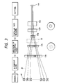
- FIG. 3 a method of manufacturing the central iron core is illustrated in Fig. 3.
- a number of wire rods 30 are first taken up by bobbins 40 and then aligned through alignment guides 41 a and 41 b so that an insulating layer is attached to each of the wire rods 30 in an insulating-layer attaching process section 42. before successively inserting them into circular dies 43a, 43b and 43c. Thereafter, in the circular dies 43a, 43b and 43c, the respective wire rods 30 are bundled and drawn so as to take a predetermined packing density to improve the space factor.
- the end portions of the respective wire rods 30 are drawn by means of a drawing chuck 44, and the drawing tension due to the drawing chuck 44 depends upon the diameter of the wire rod 30 and the degree of the space factor.
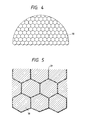
- the wire rod assembly bundled substantially has ahexagon configuration, and the space factor of the magnetic material in the central iron core 20 becomes above 80%.
- Fig. 5 shows an enlarged cross section thereof. In the case that the space factor is above 85%, insulating layers 31 are required to be placed between the respective wire rods 30.
- thermoplastic resin for example, polyethylene (PE), polypropylene (PP), polystyrene (PS), hydrocarbon resin such as ABS resins, acrylic resins such as methyl metaacrylates (PMMA), vinyl acetate resins such as vinyl acetate resins and vinyl acetate copolymers, vinyl chlorides (PVC), vinylidene chlorides (PVDC), halogen containing resins such as fluorine, polycarbonates (PC), polyester resins such as saturated polyester (PBT), polyamide resins such as 6 nylon, 66 nylon, 11 nylon and 12 nylon, poly phenylene oxide (PPO), polyether resins such as polyacetal (POM), and poly ether ether ketone (PEEK) resins, PET resins, polyimide resins ⁇ .
- thermoplastic resin for example, polyethylene (PE), polypropylene (PP), polystyrene (PS), hydrocarbon resin such as ABS resins, acrylic resins such as methyl metaacrylates (PMMA), vinyl acetate resins such as vinyl
- a number of wire rods 30 whose surfaces are coated with an insulating material are cut to have a predetermined length and then bundled and charged in a space formed by upper and lower dies coated with a mold lubricant so that the appearance of the product has a circular configuration, before performing the press formation with heating from the external.
- a cylindrical ignition coil having an outer diameter of 22 mm and a length of 68 mm is trially produced where the diameter of the central iron core 20 is 8.0 mm, the number of turns of the primary coil 24 is 132 and the number of turns of the secondary coil 25 is 13200.
- the generation voltage is lowered as illustrated by the X-mark if the insulation is insufficient.
- the insulation process is required for the region that the space factor is above 85% (in the case that the space factor is below 85%, there are spaces irrespective of no insulation process, thereby allowing the insulation).
- the diameter of the wire rods 30 is preferable to be smaller (little deterioration at high frequency), while, in the case of being below 0.01 mm, when improving the space factor under the condition of the execution of the insulation process of the wire rods 30, difficulty is actually encountered to obtain the more-than 95%.
- the diameter of the wire rods 30 is small, the number of the wire rods to be bundled becomes large for forming the central iron core 20 having a predetrmined diameter, which results in being complex in the process, increasing the cost and making easy the breaking of the wire rods 30 on bundling.
- the diameter of the wire rods 30 becomes above 3 mm, an eddy current occurs in the wire rod so as to lower the secondary generation voltage.
- each of the wire rods made of a grain oriented silicon steel has a diameter of 0.01 to 3 mm and the magnetic flux density B 8 is 1.95 T (tesla) under the condition that the magnetic field is 8 oersteds.
- the space factor above 57.5% allows the secondary generation voltage above 30 KV.
- the wire rods made of a permenjule Fe compound including 50% Co
- the secondary generation voltage V is made in accordance with the following equation (1) where
- the eddy current A' becomes greater in accordance with increase in the diameter of the wire rod, and tends to become greater when no insulation.
- a preferable diameter of teh wire rod is below 2 mm.
- the surface area of the wire rod becomes wide to require an insulating coat. The much insulating coat requirement reduces the space factor of the wire rod material (the ratio of the material in the cross-sectional area). The test result based upon this fact is shown in Fig. 7.
- the kind of the wire rods 30 it is possible to use any one of materials which has a great saturated magnetic flux density and a good soft magnetic characteristic.
- the space factor of the wire rods is above 73% and the electrical insulation resistance between the respective wire rods is above 5 Qcm.
- the central iron core 20 formed by bundling wire rods to have a circular-pole-like configuration is arranged so that both end portions 20a and 20b thereof respectively have square configurations.
- Forming both the end portions 20a and 20b to square configurations allows that angular plane magnets which are cheaper in cost than the cylindrical magnets are provided at the four or three sides of each of both the end portions 20a and 20b and further gaps between the magnets 23 and the end portions 20a, 20b are reduced so as to reduce the leakage of the magnetic flux to improve the performance.
- a material 32 in which resin powder (0.5 to 30 weight% ) is attached to a surface of metallic power (pure iron or iron including silicon) is provided at the circumference of the aligned hexagon wire rods 30 and then encased in a die having a predetemined configuration so as to be pressed and further placed as it is for one to five hours under the temperature atmosphere of 150 to 300°C so as to harden the aforementioned resin powder material (for example, araldite resin, epoxy resin).
- the metallic powder is charged in gaps between the hexagon wire rods which are presented at the peripheral portion. This charging (packing) efficiency reaches above 90%, thereby improving the characteristic.
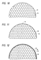
- wire rods 30 such as circular rods, triangular rods, square rods and hexagon rods are placed in a silicon steel pipe 33 and then heated in a temperature range of 300 to 900°C so as to repeatedly perform the warm drawing operation several times using dies with different diameters in order to gradually reduce the outer diameter of the silicon steel pipe 33.
- the respective wire rods 30 are pressed by means of the contracting force from the external through the silicon steel pipe so as to increase the packing density.
- the insulating process (the attachment process of Si0 2 or A1 2 0 3 , or the insulating process due to the oxide such as the oxide of iron) is effected between the respective wire rods 30.
- a portion of the silicon steel pipe 30 is axially cut off and an insulating material 34 is introduced into slits formed by the cutting and fixed therein.
- the amount of the silicon of the silicon steel pipe 33 to be used herein is 0.5 to 6 weight% and the remaining is Fe or Fe-based material.
- the thickness thereof is 0.1 to 0.5 mm, preferably 0.25 to 04 mm, and the surface of the silicon steel pipe 33 is oxidation-treated. Acordingly, the space factor becomes above 90% which provides an excellent characteristic.
- This embodiment has an arrangement as illustrated in Fig. 12.
- a thin silicon steel plate 35 (having a thickness of 0.1 to 0.3 mm) is wound two or three times around wire rods 30 and then drawn in a die so as to apply a pressing force to the wire rods 30 through the thin plate, thereby producing a formation to improve the space factor.
- the silicon steel plate 35 is insulation-processed.
- the overlapping degree of the silicon steel plate 35 increases in accordance with the contraction of the outer diameter thereof, since the silicon steel plate 35 is insulated at a portion on the circumference, it is possible to suppress generation of the eddy current. This can keep the space factor to above 90% to provide a good characteristic.
- An ignition coil assembly to be inserted into a plug hole of an engine so as to be directly coupled to an ignition plug.
- the ignition coil assembly is equipped with a central iron core and primary and secondary coils wound around the central iron core.
- the central iron core is formed by bundling magnetic wire rods to have a cylindrical configuration. This arrangement allows the ignition coil assembly to be easily and effectively inserted into the plug hole of the engine.
Landscapes
- Engineering & Computer Science (AREA)
- Power Engineering (AREA)
- Chemical & Material Sciences (AREA)
- Combustion & Propulsion (AREA)
- Mechanical Engineering (AREA)
- General Engineering & Computer Science (AREA)
- Manufacturing & Machinery (AREA)
- Ignition Installations For Internal Combustion Engines (AREA)
Applications Claiming Priority (2)
| Application Number | Priority Date | Filing Date | Title |
|---|---|---|---|
| JP202228/90 | 1990-07-30 | ||
| JP2202228A JP3018424B2 (ja) | 1990-07-30 | 1990-07-30 | 内燃機関用コイルの中心鉄心の製造方法 |
Publications (2)
| Publication Number | Publication Date |
|---|---|
| EP0469530A1 true EP0469530A1 (fr) | 1992-02-05 |
| EP0469530B1 EP0469530B1 (fr) | 1996-01-03 |
Family
ID=16454085
Family Applications (1)
| Application Number | Title | Priority Date | Filing Date |
|---|---|---|---|
| EP91112748A Expired - Lifetime EP0469530B1 (fr) | 1990-07-30 | 1991-07-29 | Dispositif de bobine d'allumage couplé directement à bougie d'allumage pour moteur à combustion interne |
Country Status (4)
| Country | Link |
|---|---|
| US (1) | US5268663A (fr) |
| EP (1) | EP0469530B1 (fr) |
| JP (1) | JP3018424B2 (fr) |
| DE (1) | DE69116023T2 (fr) |
Cited By (6)
| Publication number | Priority date | Publication date | Assignee | Title |
|---|---|---|---|---|
| FR2784496A1 (fr) * | 1998-09-28 | 2000-04-14 | Sagem | Circuit magnetique pour transformateur d'energie electrique |
| EP0905722A3 (fr) * | 1997-09-18 | 2000-07-05 | Sumitomo Wiring Systems, Ltd. | Bobine d'allumage à champ magnétique de sens opposé |
| EP0898289A3 (fr) * | 1997-08-07 | 2000-09-27 | Sumitomo Wiring Systems, Ltd. | Bobine d'allumage comprenant un aimant en forme de tore |
| EP1026394A3 (fr) * | 1999-02-08 | 2002-07-03 | Hitachi, Ltd. | Bobine d'allumage pour moteur à combustion interne |
| EP2449565A4 (fr) * | 2009-07-02 | 2017-10-11 | Delphi Technologies, Inc. | Bobine d'allumage |
| WO2019135044A1 (fr) * | 2018-01-05 | 2019-07-11 | Socomec | Transformateur de courant ouvrant a noyau magnetique souple |
Families Citing this family (20)
| Publication number | Priority date | Publication date | Assignee | Title |
|---|---|---|---|---|
| EP0716436B1 (fr) | 1994-12-06 | 1998-09-30 | Denso Corporation | Bobine d'allumage pour un moteur à combustion interne |
| JPH09186029A (ja) * | 1995-12-27 | 1997-07-15 | Aisan Ind Co Ltd | 内燃機関用点火コイル |
| JPH09320865A (ja) * | 1996-05-29 | 1997-12-12 | Aisan Ind Co Ltd | 内燃機関用点火コイル |
| US6268786B1 (en) | 1998-11-30 | 2001-07-31 | Harrie R. Buswell | Shielded wire core inductive devices |
| US6522231B2 (en) | 1998-11-30 | 2003-02-18 | Harrie R. Buswell | Power conversion systems utilizing wire core inductive devices |
| US6605149B2 (en) * | 2002-01-11 | 2003-08-12 | Hemlock Semiconductor Corporation | Method of stacking polycrystalline silicon in process for single crystal production |
| US20040027222A1 (en) * | 2002-08-06 | 2004-02-12 | Hazelwood John E. | Ignition apparatus having high density cylindrical laminated core |
| JP4609698B2 (ja) * | 2004-10-08 | 2011-01-12 | 株式会社デンソー | コアの作製方法 |
| JP2006278499A (ja) * | 2005-03-28 | 2006-10-12 | Denso Corp | 点火コイル |
| DE102005039105A1 (de) * | 2005-08-18 | 2007-02-22 | Robert Bosch Gmbh | Stabzündspule mit verbessertem Stabkern |
| JP5090364B2 (ja) * | 2006-10-31 | 2012-12-05 | 三菱電機株式会社 | シート型トランスおよび放電灯点灯装置 |
| JP4960081B2 (ja) * | 2006-12-28 | 2012-06-27 | 三菱電機株式会社 | 内燃機関用点火装置 |
| JP2008172162A (ja) * | 2007-01-15 | 2008-07-24 | Denso Corp | 点火コイル用の軟磁性体 |
| US7834737B2 (en) * | 2007-09-10 | 2010-11-16 | Delphi Technologies, Inc. | Ignition apparatus having bonded steel wire central core |
| US20090199827A1 (en) * | 2008-02-08 | 2009-08-13 | Skinner Albert A | Flux director for ignition coil assembly |
| JP5923460B2 (ja) * | 2013-06-14 | 2016-05-24 | ダイヤモンド電機株式会社 | 点火コイル用誘磁鉄芯,及び,これを備える内燃機関用点火コイル |
| DE102016219281B4 (de) * | 2016-10-05 | 2018-12-13 | Bayerische Motoren Werke Aktiengesellschaft | Zündvorrichtung mit einer Feder zur elektrischen Anbindung einer Zündkerze sowie Verbrennungsmotor und Kraftfahrzeug mit einer solchen |
| JP6781647B2 (ja) * | 2017-03-08 | 2020-11-04 | 株式会社神戸製鋼所 | 磁気回路用鉄心及び磁気回路用鉄心の製造方法 |
| DE102021101928A1 (de) | 2021-01-28 | 2022-07-28 | Rolls-Royce Deutschland Ltd & Co Kg | Spulenkörper |
| TW202522521A (zh) * | 2023-10-31 | 2025-06-01 | 日商村田製作所股份有限公司 | 纖維束製成的電感器及電氣組件和其製作方法 |
Citations (5)
| Publication number | Priority date | Publication date | Assignee | Title |
|---|---|---|---|---|
| FR1533644A (fr) * | 1967-08-04 | 1968-07-19 | Lucas Industries Ltd | Noyau feuilleté, notamment pour bobine d'allumage et son procédé de fabrication |
| US4035751A (en) * | 1975-05-27 | 1977-07-12 | Ainslie Walthew | Device for inducing an electrical voltage |
| FR2442347A1 (fr) * | 1978-11-23 | 1980-06-20 | Ducellier & Cie | Bobine elevatrice de tension pour l'allumage de moteurs a combustion interne, notamment pour vehicules automobiles |
| DE3152008C1 (de) * | 1981-12-31 | 1983-07-07 | Fried. Krupp Gmbh, 4300 Essen | Langgestreckter magnetischer Schaltkern |
| EP0193079A2 (fr) * | 1985-02-27 | 1986-09-03 | Hitachi, Ltd. | Méthode de fabrication d'éléments électromagnétiques |
Family Cites Families (13)
| Publication number | Priority date | Publication date | Assignee | Title |
|---|---|---|---|---|
| US352105A (en) * | 1886-11-02 | op buda-pesth | ||
| US1307867A (en) * | 1919-06-24 | Eable p | ||
| US1497469A (en) * | 1919-02-10 | 1924-06-10 | Ames Butler | Magnetic core and method of making same |
| US1398793A (en) * | 1919-10-17 | 1921-11-29 | Peplinski Glen | Induction-coil |
| US1474152A (en) * | 1921-01-08 | 1923-11-13 | Kent Arthur Atwater | Induction coil |
| US1641374A (en) * | 1924-12-16 | 1927-09-06 | Delco Remy Corp | Induction coil |
| US2682021A (en) * | 1949-12-16 | 1954-06-22 | Gustaf W Elmen | Shredded magnetic core and method of making same |
| US2962679A (en) * | 1955-07-25 | 1960-11-29 | Gen Electric | Coaxial core inductive structures |
| GB1018738A (en) * | 1964-01-06 | 1966-02-02 | Ass Eng Ltd | Inductive probe |
| JPS4520871Y1 (fr) * | 1967-04-15 | 1970-08-20 | ||
| JPH0715853B2 (ja) * | 1986-11-21 | 1995-02-22 | 日本電装株式会社 | エネルギ−蓄積型点火コイル |
| JPS6450403A (en) * | 1987-08-20 | 1989-02-27 | Brother Ind Ltd | Composite magnetic core and manufacture thereof |
| US4800356A (en) * | 1987-12-01 | 1989-01-24 | Eaton Corporation | Shunt transformer |
-
1990
- 1990-07-30 JP JP2202228A patent/JP3018424B2/ja not_active Expired - Fee Related
-
1991
- 1991-07-29 EP EP91112748A patent/EP0469530B1/fr not_active Expired - Lifetime
- 1991-07-29 US US07/736,936 patent/US5268663A/en not_active Expired - Lifetime
- 1991-07-29 DE DE69116023T patent/DE69116023T2/de not_active Expired - Fee Related
Patent Citations (5)
| Publication number | Priority date | Publication date | Assignee | Title |
|---|---|---|---|---|
| FR1533644A (fr) * | 1967-08-04 | 1968-07-19 | Lucas Industries Ltd | Noyau feuilleté, notamment pour bobine d'allumage et son procédé de fabrication |
| US4035751A (en) * | 1975-05-27 | 1977-07-12 | Ainslie Walthew | Device for inducing an electrical voltage |
| FR2442347A1 (fr) * | 1978-11-23 | 1980-06-20 | Ducellier & Cie | Bobine elevatrice de tension pour l'allumage de moteurs a combustion interne, notamment pour vehicules automobiles |
| DE3152008C1 (de) * | 1981-12-31 | 1983-07-07 | Fried. Krupp Gmbh, 4300 Essen | Langgestreckter magnetischer Schaltkern |
| EP0193079A2 (fr) * | 1985-02-27 | 1986-09-03 | Hitachi, Ltd. | Méthode de fabrication d'éléments électromagnétiques |
Non-Patent Citations (1)
| Title |
|---|
| PATENT ABSTRACTS OF JAPAN vol. 13, no. 251 (E-771)(3599) 12 June 1989 & JP-A-1 050 403 ( BROTHER ) 27 February 1989 * |
Cited By (9)
| Publication number | Priority date | Publication date | Assignee | Title |
|---|---|---|---|---|
| EP0898289A3 (fr) * | 1997-08-07 | 2000-09-27 | Sumitomo Wiring Systems, Ltd. | Bobine d'allumage comprenant un aimant en forme de tore |
| EP0905722A3 (fr) * | 1997-09-18 | 2000-07-05 | Sumitomo Wiring Systems, Ltd. | Bobine d'allumage à champ magnétique de sens opposé |
| FR2784496A1 (fr) * | 1998-09-28 | 2000-04-14 | Sagem | Circuit magnetique pour transformateur d'energie electrique |
| EP1026394A3 (fr) * | 1999-02-08 | 2002-07-03 | Hitachi, Ltd. | Bobine d'allumage pour moteur à combustion interne |
| EP2449565A4 (fr) * | 2009-07-02 | 2017-10-11 | Delphi Technologies, Inc. | Bobine d'allumage |
| WO2019135044A1 (fr) * | 2018-01-05 | 2019-07-11 | Socomec | Transformateur de courant ouvrant a noyau magnetique souple |
| FR3076657A1 (fr) * | 2018-01-05 | 2019-07-12 | Socomec | Transformateur de courant ouvrant a noyau magnetique souple |
| CN111630615A (zh) * | 2018-01-05 | 2020-09-04 | 溯高美公司 | 包括柔性磁芯的开合式电流互感器 |
| US12027305B2 (en) | 2018-01-05 | 2024-07-02 | Socomec | Openable current transformer comprising a flexible magnetic core |
Also Published As
| Publication number | Publication date |
|---|---|
| DE69116023D1 (de) | 1996-02-15 |
| US5268663A (en) | 1993-12-07 |
| EP0469530B1 (fr) | 1996-01-03 |
| JPH0487311A (ja) | 1992-03-19 |
| DE69116023T2 (de) | 1996-05-30 |
| JP3018424B2 (ja) | 2000-03-13 |
Similar Documents
| Publication | Publication Date | Title |
|---|---|---|
| US5268663A (en) | Ignition coil assembly directly applied to ignition plug for internal combustion engine | |
| US5719546A (en) | Inductive coupler for transferring electrical power | |
| JP7373709B2 (ja) | 高周波コイル部品、無線給電用コイル部品、無線給電装置および周波コイル部品の製造方法 | |
| US4543708A (en) | Method of manufacturing an armature | |
| JP2001211591A (ja) | 半径方向に挿入されたケーブル巻線を有する高電圧発電機固定子及びその組立て方法 | |
| US6650221B2 (en) | Ignition coil for an internal combustion engine | |
| US5929736A (en) | Engine igniting coil device and method of winding an ignition coil | |
| US3496504A (en) | Terminal assembly for encapsulated electric coil | |
| WO1997041574A1 (fr) | Ensemble bobine noyau magnetique pour moteurs a explosion | |
| US8991371B2 (en) | Ignition coil | |
| US5923236A (en) | Magnetic core-coil assembly for spark ignition system | |
| US3602814A (en) | Encapsulated electric coil having barrier layer | |
| US6474322B1 (en) | Ignition device for internal combustion engine | |
| JPH07238881A (ja) | 点火コイル | |
| US6809621B2 (en) | Internal combustion engine ignition coil, and method of producing the same | |
| EP0785605A1 (fr) | Dispositif bobine d'allumage pour moteur à combustion interne | |
| US7053746B2 (en) | Pencil ignition coil | |
| JPS5814059B2 (ja) | 放電点火用トランスの製造方法 | |
| EP0893599A1 (fr) | Bobine d'allumage à noyau ouvert et entrefer central | |
| JPS608420Y2 (ja) | 点火コイル | |
| US7834737B2 (en) | Ignition apparatus having bonded steel wire central core | |
| WO1997041576A1 (fr) | Ensemble bobine/noyau magnetiques pour systeme d'allumage commande | |
| JP3341755B2 (ja) | 電磁コイルおよびそれを用いた内燃機関用点火コイル | |
| JPH09167710A (ja) | 内燃機関用点火コイル | |
| KR20000065128A (ko) | 스파크점화시스템용자기코어-코일어셈블리 |
Legal Events
| Date | Code | Title | Description |
|---|---|---|---|
| PUAI | Public reference made under article 153(3) epc to a published international application that has entered the european phase |
Free format text: ORIGINAL CODE: 0009012 |
|
| AK | Designated contracting states |
Kind code of ref document: A1 Designated state(s): DE FR GB |
|
| 17P | Request for examination filed |
Effective date: 19911230 |
|
| 17Q | First examination report despatched |
Effective date: 19940628 |
|
| GRAA | (expected) grant |
Free format text: ORIGINAL CODE: 0009210 |
|
| AK | Designated contracting states |
Kind code of ref document: B1 Designated state(s): DE FR GB |
|
| REF | Corresponds to: |
Ref document number: 69116023 Country of ref document: DE Date of ref document: 19960215 |
|
| ET | Fr: translation filed | ||
| PLBE | No opposition filed within time limit |
Free format text: ORIGINAL CODE: 0009261 |
|
| 26N | No opposition filed | ||
| REG | Reference to a national code |
Ref country code: GB Ref legal event code: 746 Effective date: 19970116 |
|
| REG | Reference to a national code |
Ref country code: GB Ref legal event code: IF02 |
|
| PGFP | Annual fee paid to national office [announced via postgrant information from national office to epo] |
Ref country code: DE Payment date: 20070726 Year of fee payment: 17 |
|
| PGFP | Annual fee paid to national office [announced via postgrant information from national office to epo] |
Ref country code: GB Payment date: 20070725 Year of fee payment: 17 |
|
| PGFP | Annual fee paid to national office [announced via postgrant information from national office to epo] |
Ref country code: FR Payment date: 20070710 Year of fee payment: 17 |
|
| GBPC | Gb: european patent ceased through non-payment of renewal fee |
Effective date: 20080729 |
|
| PG25 | Lapsed in a contracting state [announced via postgrant information from national office to epo] |
Ref country code: DE Free format text: LAPSE BECAUSE OF NON-PAYMENT OF DUE FEES Effective date: 20090203 |
|
| REG | Reference to a national code |
Ref country code: FR Ref legal event code: ST Effective date: 20090331 |
|
| PG25 | Lapsed in a contracting state [announced via postgrant information from national office to epo] |
Ref country code: GB Free format text: LAPSE BECAUSE OF NON-PAYMENT OF DUE FEES Effective date: 20080729 |
|
| PG25 | Lapsed in a contracting state [announced via postgrant information from national office to epo] |
Ref country code: FR Free format text: LAPSE BECAUSE OF NON-PAYMENT OF DUE FEES Effective date: 20080731 |