EP0469658A2 - Verfahren zur Analyse der Zylinderleistung einer Brennkraftmaschine - Google Patents
Verfahren zur Analyse der Zylinderleistung einer Brennkraftmaschine Download PDFInfo
- Publication number
- EP0469658A2 EP0469658A2 EP91201755A EP91201755A EP0469658A2 EP 0469658 A2 EP0469658 A2 EP 0469658A2 EP 91201755 A EP91201755 A EP 91201755A EP 91201755 A EP91201755 A EP 91201755A EP 0469658 A2 EP0469658 A2 EP 0469658A2
- Authority
- EP
- European Patent Office
- Prior art keywords
- cylinder
- top dead
- engine
- dead centre
- speed
- Prior art date
- Legal status (The legal status is an assumption and is not a legal conclusion. Google has not performed a legal analysis and makes no representation as to the accuracy of the status listed.)
- Granted
Links
Images


Classifications
-
- G—PHYSICS
- G01—MEASURING; TESTING
- G01M—TESTING STATIC OR DYNAMIC BALANCE OF MACHINES OR STRUCTURES; TESTING OF STRUCTURES OR APPARATUS, NOT OTHERWISE PROVIDED FOR
- G01M15/00—Testing of engines
- G01M15/04—Testing internal-combustion engines
- G01M15/042—Testing internal-combustion engines by monitoring a single specific parameter not covered by groups G01M15/06 - G01M15/12
- G01M15/046—Testing internal-combustion engines by monitoring a single specific parameter not covered by groups G01M15/06 - G01M15/12 by monitoring revolutions
-
- F—MECHANICAL ENGINEERING; LIGHTING; HEATING; WEAPONS; BLASTING
- F02—COMBUSTION ENGINES; HOT-GAS OR COMBUSTION-PRODUCT ENGINE PLANTS
- F02D—CONTROLLING COMBUSTION ENGINES
- F02D2200/00—Input parameters for engine control
- F02D2200/02—Input parameters for engine control the parameters being related to the engine
- F02D2200/10—Parameters related to the engine output, e.g. engine torque or engine speed
- F02D2200/1015—Engines misfires
Definitions
- This invention relates to a method of analyzing cylinder performance in an internal combustion engine.
- the diagnostic connector on automobiles permits service personnel to diagnose quickly problems related to the operation of on-board sensors and microcomputers. There is a need, however, for the capability to diagnose individual cylinder performance, that is, to identify misfiring or otherwise under-performing cylinders.
- Such information in the form of compression pressure and power output values for each cylinder, can be obtained from engine speed variations caused by the compression and power strokes of each cylinder.
- Low resolution sensors are commonly used on engines for ignition timing and are capable of delivering a speed sample each 60 or 30°, for example.
- the present invention seeks to provide an improved method of analysing cylinder performance.
- an aspect of the present invention provides a method of analysing cylinder performance of an internal combustion engine as defined in claim 1.
- the diagnostic method set forth in the ensuing description was specifically developed for a four cylinder gasoline engine with a fuel injector for each cylinder and having a sensor which delivers six pulses per crankshaft revolution (6X encoder). It will be understood, however, that the method applies equally well to engines with six or eight cylinders, for example, using 6X, 12X, 18X or 24X encoders, with suitable adjustments to suit the number of cylinders and the type of encoder.
- an engine 10 includes an encoder 12 mounted on and rotated by the engine crankshaft 14 and which has teeth 16 equally spaced around its circumference at 60° intervals.
- An electromagnetic speed sensor 18 positioned adjacent the path of the teeth 16 senses the passing of the teeth as the crankshaft 14 is rotated and provides an alternating output to a zero crossing responsive square wave amplifier 20 whose output is a square wave signal at the frequency of the alternating input from the speed sensor 18.
- This square wave signal is provided to a pulse generator 22 which provides a pulse output with the passing of each tooth of the encoder 12. Therefore the time interval between pulses is inversely proportional to engine speed and the frequency of the pulses is directly proportional to engine speed.
- a computer 24, of conventional type receives the pulses developed by the pulse generator 22.
- the computer 24 comprises a microprocessor, a clock, a read-only memory, a random access memory, a power supply unit, an input counter interface and an output interface.
- the computer 24, upon a manual input command or upon sensing certain engine conditions, executes an operating program stored in its read-only memory. This program includes steps for reading input data and timing intervals via the input counter interface, processing the input data and providing for an output such as to a display 26 via the output interface.
- the display 26 may take the form of a printer or a video monitor for displaying various information relating to the diagnostic procedure.
- a low resolution trace of engine speed is obtained as shown in Figure 2 by the trace 30 which is registered with scale markings for the engine rotation angle; where 0° coincides with the top dead centre of one cylinder and each 180° increment corresponds to the top dead centre of another cylinder.
- the trace 30 is made up of a succession of 60° samples each aligned with an angular period and representing the average speed over that 60 0 period.
- the speed samples cover intervals immediately before and after top dead centre, respectively denoted S(-L) and S(+L), since they are relatively low values for a normally operating engine, and a relatively high sample S(H) which occurs in an interval midway between top dead centre of successive cylinders.
- a high resolution speed trace 32 derived from speed samples taken every 4° of crank rotation is superimposed on the Figure 2 graph to reveal the relationship of the low resolution trace 30 to actual engine speed.
- the lowest speeds shown by the trace occur at about the top dead centre of each cylinder and the highest speed is about midway between top dead centres, or 90 0 before or after, top dead centre. More precisely, the actual speed peaks shortly before the 90° position and the speed at the 90° position is about equal to the measured average speed S(H) at the midway point.
- the method involves estimating the instantaneous speed of the engine at top dead centre and midway between top dead centres from the low resolution trace 30.
- V(L) If one of the cylinders malfunctions, the value V(L) for that cylinder is over-estimated by about 1 %.
- the values of V(L) for the remaining, properly functioning cylinders are, as a consequence, under-estimated by about 1 %, except for the cylinder which is next in the firing order after the malfunctioning one.
- V(L) can be up to 3.5% below the actual value.
- the actual speed trace 32 is replaced by a V-shaped estimated trace 34.
- the midway speed V(-H) before top dead centre, the speed V(L) at top dead centre and the midway speed V( + H) after top dead centre define the trace and contain sufficient information to analyse cylinder performance.
- the compression of the cylinder determines the slope of the trace before top dead centre and thus the difference of V(-H) and V(L) reveals information about compression.
- a variety of equations can be constructed to extract that information in one form or another. For example, relative compression RCP can be determined by
- Negative, or distinctly lower values of RCP and/or RPO for a particular cylinder in comparison with those of the other cylinders indicate a compression or a combustion problem in that cylinder.
- the values of RCP and RPO are very close, and are in the range of 2% to 8% depending on engine calibration and operating conditions.
- a speed trace 34 for a complete engine cycle during proper operation is shown in Figure S overlaid on the actual speed trace 32.
- the diagnostic speed trace is thus a series of V shaped forms and is hereinafter called the engine speed signature.
- Only nine data points comprising the high and low speed points V(H) and V(L) are required to define the signature for an entire engine cycle in contrast to 180 points needed to define a high resolution speed trace. It is therefore relatively easy to build a library of such signatures linked to a variety of known engine problems.
- the small number of data points in each signature makes an automatic pattern search very fast and simple. An original speed signature taken when the engine is new could be stored in the engine computer for reference for future use.
- a trace of a speed signature is shown in Figure 6 for an engine having the spark plug disconnected in cylinder 2.
- the RCP and RPO parameters for each cylinder are shown as Comp. and Power.
- the speed after top dead centre falls off instead of increasing and the power parameter RPO drops to -4 from a normal of 5 for the preceding cylinders.
- the drop in speed also affects the next cylinder, No. 1, which shows an RPO of 10 due to the gain in engine speed.
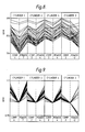
- Figure 7 is a display of an overlay of 25 consecutive signatures.
- the same signature shape is shown by each signature, revealing consistent engine operation.
- the narrow band indicates relatively little speed variation from cycle to cycle.
- Figure 8 is an overlay of 25 signatures for an engine having intermittent misfire for cylinder 2. Each misfire results in a speed drop during the power stroke (after top dead centre) which leads to lower speeds for subsequent cycles.
- the composite RPO value for cylinder 2 is -2 compared to 4 and 7 for the other cylinders.
- the overlay of several signatures clearly reveals the intermittent failures of either injectors or ignition.
- a particularly useful form of display of speed signatures is provided by normalizing the data for each cylinder to the estimated top dead centre speed, V(L), and displaying the trace of several normalized speed signatures. This gives the operator very clear indication of the engine operation, especially in the case of intermittent misfires.
- Figure 9 is the overlay of normalized signatures for the same data used to generate Figure 8 signatures. The normalized trace is prepared by dividing V(-H), V(L) and V(+H) by V(L) for each individual cylinder.
- the method is carried out in the computer 24 by a program represented by the flow chart shown in Figure 10.
- the engine speed is sensed (block 40) by receiving the pulses initiated by the crankshaft encoder 12, the average speed is calculated for each period between pulses (block 42), the high speeds V(H) at the midway points are determined from the average speeds S(H) (block 44), the low speeds V(L) at top dead centres are calculated (block 46), compression and power out parameters for each cylinder are calculated based on the differences between V(H) and V(L) for the compression and combustion phases, respectively (block 48), the engine speed signature is displayed for one cycle (block 50) or an overlay of several signatures is displayed (block 52). Alternatively, the estimated data is normalized (block 54) and normalized speed signatures are displayed (block 56).
Landscapes
- Chemical & Material Sciences (AREA)
- Engineering & Computer Science (AREA)
- Combustion & Propulsion (AREA)
- Physics & Mathematics (AREA)
- General Physics & Mathematics (AREA)
- Combined Controls Of Internal Combustion Engines (AREA)
- Testing Of Engines (AREA)
Applications Claiming Priority (2)
| Application Number | Priority Date | Filing Date | Title |
|---|---|---|---|
| US07/559,852 US5132909A (en) | 1990-07-30 | 1990-07-30 | Apparatus for diagnosing individual cylinder performance by estimated instantaneous engine speeds |
| US559852 | 1990-07-30 |
Publications (3)
| Publication Number | Publication Date |
|---|---|
| EP0469658A2 true EP0469658A2 (de) | 1992-02-05 |
| EP0469658A3 EP0469658A3 (en) | 1992-12-23 |
| EP0469658B1 EP0469658B1 (de) | 1995-03-29 |
Family
ID=24235304
Family Applications (1)
| Application Number | Title | Priority Date | Filing Date |
|---|---|---|---|
| EP91201755A Expired - Lifetime EP0469658B1 (de) | 1990-07-30 | 1991-07-05 | Verfahren zur Analyse der Zylinderleistung einer Brennkraftmaschine |
Country Status (4)
| Country | Link |
|---|---|
| US (1) | US5132909A (de) |
| EP (1) | EP0469658B1 (de) |
| JP (1) | JPH0750017B2 (de) |
| DE (1) | DE69108475T2 (de) |
Cited By (5)
| Publication number | Priority date | Publication date | Assignee | Title |
|---|---|---|---|---|
| EP0584750B1 (de) * | 1992-08-21 | 1997-03-05 | Chrysler Corporation | Verfahren und Vorrichtung zum Erfassen von Verbrennungsaussetzern in einer Brennkraftmaschine mittels zweier Sensoren |
| EP0750184A3 (de) * | 1995-06-22 | 1997-06-18 | Avl Verbrennungskraft Messtech | Verfahren und Einrichtung zur Diagnose mehrzylindriger Brennkraftmaschinen |
| FR2751410A1 (fr) * | 1996-07-19 | 1998-01-23 | Renault | Procede et installation pour tester individuellement des moteurs a combustion produits en chaine |
| WO2008127176A1 (en) * | 2007-04-13 | 2008-10-23 | Engstroem Christian | Method and device for testing of a combustion engine or an associated structure and a rig |
| CN110686890A (zh) * | 2019-10-23 | 2020-01-14 | 中船动力有限公司 | 在线柴油机气阀状态检测方法 |
Families Citing this family (11)
| Publication number | Priority date | Publication date | Assignee | Title |
|---|---|---|---|---|
| DE4009285A1 (de) * | 1989-08-23 | 1990-12-20 | Audi Ag | Verfahren zur zylinderselektiven ueberwachung des energieumsatzes bei einer mehrzylinder-brennkraftmaschine |
| JPH0781935B2 (ja) * | 1991-08-29 | 1995-09-06 | トヨタ自動車株式会社 | 多気筒内燃機関の失火検出装置 |
| JP2606019B2 (ja) * | 1991-09-18 | 1997-04-30 | 三菱電機株式会社 | 内燃機関の失火検出装置 |
| US5446664A (en) * | 1992-10-07 | 1995-08-29 | Spx Corporation | Method and apparatus for diagnosing faulty cylinders in internal combustion engines |
| US5445014A (en) * | 1994-08-12 | 1995-08-29 | Briggs & Stratton Corporation | Electronic engine load and revolution sensing device |
| US5680311A (en) * | 1995-12-29 | 1997-10-21 | Snap-On Tools Company | Long term firing and spark display |
| US6786084B2 (en) * | 2003-01-13 | 2004-09-07 | Delphi Technologies, Inc. | Sensor assembly and method for non-intrusively sensing instantaneous speed of the engine of a vehicle |
| US7010460B2 (en) * | 2003-10-30 | 2006-03-07 | Snap-On Incorporated | Reciprocating engine cylinder contribution tester and method |
| US7205759B2 (en) * | 2005-02-24 | 2007-04-17 | Delphi Technologies, Inc. | Apparatus and method for determining an engine speed |
| US7499793B2 (en) * | 2007-05-14 | 2009-03-03 | Delphi Technologies, Inc. | System for discrimination of spurious crank encoder signals |
| DE102010009648A1 (de) * | 2010-02-27 | 2011-09-01 | Robert Bosch Gmbh | Verfahren zur Bestimmung einer Drehzahl einer Antriebswelle einer Brennkraftmaschine |
Family Cites Families (10)
| Publication number | Priority date | Publication date | Assignee | Title |
|---|---|---|---|---|
| GB1434036A (en) * | 1972-08-11 | 1976-04-28 | Cav Ltd | Test systems for internal combustion engines |
| DE2633908A1 (de) * | 1976-07-28 | 1978-02-02 | Siemens Ag | Pruefverfahren fuer eine hubkolben- brennkraftmaschine |
| DE3150085A1 (de) * | 1981-12-17 | 1983-07-07 | Fraunhofer-Gesellschaft zur Förderung der angewandten Forschung e.V., 8000 München | "analyse der winkelgeschwindigkeit von verbrennungsmotoren zur funktionsueberwachung der zylinder" |
| US4539841A (en) * | 1984-02-13 | 1985-09-10 | General Motors Corporation | Method of determining engine cylinder compression pressure and power output |
| US4562728A (en) * | 1984-12-03 | 1986-01-07 | United Technologies Corporation | Absolute compression test |
| US4697561A (en) * | 1985-04-15 | 1987-10-06 | Purdue Research Foundation | On-line engine torque and torque fluctuation measurement for engine control utilizing crankshaft speed fluctuations |
| DE3879713T2 (de) * | 1988-07-01 | 1993-08-19 | Bosch Gmbh Robert | Auswertung einer schwankenden veraenderlichen. |
| US4893244A (en) * | 1988-08-29 | 1990-01-09 | General Motors Corporation | Predictive spark timing method |
| US4932379A (en) * | 1989-05-01 | 1990-06-12 | General Motors Corporation | Method for detecting engine misfire and for fuel control |
| US5041980A (en) * | 1990-06-04 | 1991-08-20 | Caterpillar Inc. | Method and apparatus for producing fault signals responsive to malfunctions in individual engine cylinders |
-
1990
- 1990-07-30 US US07/559,852 patent/US5132909A/en not_active Expired - Lifetime
-
1991
- 1991-07-05 DE DE69108475T patent/DE69108475T2/de not_active Expired - Fee Related
- 1991-07-05 EP EP91201755A patent/EP0469658B1/de not_active Expired - Lifetime
- 1991-07-30 JP JP3190105A patent/JPH0750017B2/ja not_active Expired - Lifetime
Cited By (6)
| Publication number | Priority date | Publication date | Assignee | Title |
|---|---|---|---|---|
| EP0584750B1 (de) * | 1992-08-21 | 1997-03-05 | Chrysler Corporation | Verfahren und Vorrichtung zum Erfassen von Verbrennungsaussetzern in einer Brennkraftmaschine mittels zweier Sensoren |
| EP0750184A3 (de) * | 1995-06-22 | 1997-06-18 | Avl Verbrennungskraft Messtech | Verfahren und Einrichtung zur Diagnose mehrzylindriger Brennkraftmaschinen |
| FR2751410A1 (fr) * | 1996-07-19 | 1998-01-23 | Renault | Procede et installation pour tester individuellement des moteurs a combustion produits en chaine |
| WO2008127176A1 (en) * | 2007-04-13 | 2008-10-23 | Engstroem Christian | Method and device for testing of a combustion engine or an associated structure and a rig |
| US8387449B2 (en) | 2007-04-13 | 2013-03-05 | Christian Engström | Method and device for testing of a combustion engine or an associated structure and a rig |
| CN110686890A (zh) * | 2019-10-23 | 2020-01-14 | 中船动力有限公司 | 在线柴油机气阀状态检测方法 |
Also Published As
| Publication number | Publication date |
|---|---|
| DE69108475D1 (de) | 1995-05-04 |
| US5132909A (en) | 1992-07-21 |
| EP0469658A3 (en) | 1992-12-23 |
| DE69108475T2 (de) | 1995-07-27 |
| JPH04232828A (ja) | 1992-08-21 |
| JPH0750017B2 (ja) | 1995-05-31 |
| EP0469658B1 (de) | 1995-03-29 |
Similar Documents
| Publication | Publication Date | Title |
|---|---|---|
| EP0469658B1 (de) | Verfahren zur Analyse der Zylinderleistung einer Brennkraftmaschine | |
| US4539841A (en) | Method of determining engine cylinder compression pressure and power output | |
| CA1139966A (en) | Relative power contribution of an internal combustion engine | |
| US5915272A (en) | Method of detecting low compression pressure responsive to crankshaft acceleration measurement and apparatus therefor | |
| US5041980A (en) | Method and apparatus for producing fault signals responsive to malfunctions in individual engine cylinders | |
| EP0475566B1 (de) | Vorrichtung und Verfahren zur Fehlzündungsanzeige in einem Verbrennungsmotor | |
| US4292670A (en) | Diagnosis of engine power and compression balance | |
| US4291383A (en) | Spark plug load testing for an internal combustion engine | |
| EP0184536B1 (de) | Absoluter Kompressionstest | |
| US4302814A (en) | Relative exhaust back-pressure of an internal combustion engine | |
| US5311123A (en) | Method of measuring the instantaneous shaft velocity of a rotary machine | |
| US4358828A (en) | Engine speed measuring system | |
| JP2666232B2 (ja) | 内燃エンジンの燃焼状態検出装置 | |
| US4398259A (en) | Snap acceleration method of diagnosing faults in internal combustion engines | |
| US4061025A (en) | Speed-related indication comparisons in internal combustion engine diagnostics | |
| US4520658A (en) | Method of locating engine top dead center position | |
| JP2682212B2 (ja) | 内燃機関の失火検出装置 | |
| GB2052071A (en) | Engine Speed Measuring System | |
| EP0258694A2 (de) | Verfahren zur Feststellung des Steuerungsprofils für jeden Zylinder in einer Brennkraftmaschine | |
| GB2143039A (en) | Timing apparatus for rotating parts |
Legal Events
| Date | Code | Title | Description |
|---|---|---|---|
| PUAI | Public reference made under article 153(3) epc to a published international application that has entered the european phase |
Free format text: ORIGINAL CODE: 0009012 |
|
| AK | Designated contracting states |
Kind code of ref document: A2 Designated state(s): DE FR GB |
|
| PUAL | Search report despatched |
Free format text: ORIGINAL CODE: 0009013 |
|
| AK | Designated contracting states |
Kind code of ref document: A3 Designated state(s): DE FR GB |
|
| 17P | Request for examination filed |
Effective date: 19921224 |
|
| 17Q | First examination report despatched |
Effective date: 19931228 |
|
| GRAA | (expected) grant |
Free format text: ORIGINAL CODE: 0009210 |
|
| AK | Designated contracting states |
Kind code of ref document: B1 Designated state(s): DE FR GB |
|
| REF | Corresponds to: |
Ref document number: 69108475 Country of ref document: DE Date of ref document: 19950504 |
|
| ET | Fr: translation filed | ||
| PLBE | No opposition filed within time limit |
Free format text: ORIGINAL CODE: 0009261 |
|
| STAA | Information on the status of an ep patent application or granted ep patent |
Free format text: STATUS: NO OPPOSITION FILED WITHIN TIME LIMIT |
|
| 26N | No opposition filed | ||
| REG | Reference to a national code |
Ref country code: GB Ref legal event code: IF02 |
|
| PGFP | Annual fee paid to national office [announced via postgrant information from national office to epo] |
Ref country code: FR Payment date: 20020619 Year of fee payment: 12 |
|
| PGFP | Annual fee paid to national office [announced via postgrant information from national office to epo] |
Ref country code: GB Payment date: 20020626 Year of fee payment: 12 |
|
| PGFP | Annual fee paid to national office [announced via postgrant information from national office to epo] |
Ref country code: DE Payment date: 20020730 Year of fee payment: 12 |
|
| PG25 | Lapsed in a contracting state [announced via postgrant information from national office to epo] |
Ref country code: GB Free format text: LAPSE BECAUSE OF NON-PAYMENT OF DUE FEES Effective date: 20030705 |
|
| PG25 | Lapsed in a contracting state [announced via postgrant information from national office to epo] |
Ref country code: DE Free format text: LAPSE BECAUSE OF NON-PAYMENT OF DUE FEES Effective date: 20040203 |
|
| GBPC | Gb: european patent ceased through non-payment of renewal fee |
Effective date: 20030705 |
|
| PG25 | Lapsed in a contracting state [announced via postgrant information from national office to epo] |
Ref country code: FR Free format text: LAPSE BECAUSE OF NON-PAYMENT OF DUE FEES Effective date: 20040331 |
|
| REG | Reference to a national code |
Ref country code: FR Ref legal event code: ST |