EP0469659A1 - Simultane Entfernung von SO2 und H2S aus Abgasen - Google Patents
Simultane Entfernung von SO2 und H2S aus Abgasen Download PDFInfo
- Publication number
- EP0469659A1 EP0469659A1 EP91201757A EP91201757A EP0469659A1 EP 0469659 A1 EP0469659 A1 EP 0469659A1 EP 91201757 A EP91201757 A EP 91201757A EP 91201757 A EP91201757 A EP 91201757A EP 0469659 A1 EP0469659 A1 EP 0469659A1
- Authority
- EP
- European Patent Office
- Prior art keywords
- stage
- suspension
- zno
- zns
- sump
- Prior art date
- Legal status (The legal status is an assumption and is not a legal conclusion. Google has not performed a legal analysis and makes no representation as to the accuracy of the status listed.)
- Granted
Links
- 239000007789 gas Substances 0.000 title claims abstract description 36
- 230000008030 elimination Effects 0.000 title abstract 2
- 238000003379 elimination reaction Methods 0.000 title abstract 2
- 239000000725 suspension Substances 0.000 claims abstract description 48
- 238000000034 method Methods 0.000 claims abstract description 13
- 238000000926 separation method Methods 0.000 claims description 2
- 229910052984 zinc sulfide Inorganic materials 0.000 description 11
- 238000006243 chemical reaction Methods 0.000 description 6
- 239000003344 environmental pollutant Substances 0.000 description 5
- 231100000719 pollutant Toxicity 0.000 description 5
- NINIDFKCEFEMDL-UHFFFAOYSA-N Sulfur Chemical compound [S] NINIDFKCEFEMDL-UHFFFAOYSA-N 0.000 description 4
- QAOWNCQODCNURD-UHFFFAOYSA-N Sulfuric acid Chemical compound OS(O)(=O)=O QAOWNCQODCNURD-UHFFFAOYSA-N 0.000 description 4
- 229910052717 sulfur Inorganic materials 0.000 description 4
- 239000011593 sulfur Substances 0.000 description 4
- 239000003054 catalyst Substances 0.000 description 3
- GWEVSGVZZGPLCZ-UHFFFAOYSA-N Titan oxide Chemical compound O=[Ti]=O GWEVSGVZZGPLCZ-UHFFFAOYSA-N 0.000 description 2
- QVGXLLKOCUKJST-UHFFFAOYSA-N atomic oxygen Chemical compound [O] QVGXLLKOCUKJST-UHFFFAOYSA-N 0.000 description 2
- 238000004519 manufacturing process Methods 0.000 description 2
- VNWKTOKETHGBQD-UHFFFAOYSA-N methane Chemical compound C VNWKTOKETHGBQD-UHFFFAOYSA-N 0.000 description 2
- 239000000203 mixture Substances 0.000 description 2
- 229910052760 oxygen Inorganic materials 0.000 description 2
- 239000001301 oxygen Substances 0.000 description 2
- 238000001179 sorption measurement Methods 0.000 description 2
- 238000005406 washing Methods 0.000 description 2
- 238000006887 Ullmann reaction Methods 0.000 description 1
- 239000005083 Zinc sulfide Substances 0.000 description 1
- 239000007900 aqueous suspension Substances 0.000 description 1
- CJDPJFRMHVXWPT-UHFFFAOYSA-N barium sulfide Chemical compound [S-2].[Ba+2] CJDPJFRMHVXWPT-UHFFFAOYSA-N 0.000 description 1
- 238000001311 chemical methods and process Methods 0.000 description 1
- 238000005660 chlorination reaction Methods 0.000 description 1
- 238000003795 desorption Methods 0.000 description 1
- 239000000446 fuel Substances 0.000 description 1
- 239000003077 lignite Substances 0.000 description 1
- 239000003345 natural gas Substances 0.000 description 1
- TWNQGVIAIRXVLR-UHFFFAOYSA-N oxo(oxoalumanyloxy)alumane Chemical compound O=[Al]O[Al]=O TWNQGVIAIRXVLR-UHFFFAOYSA-N 0.000 description 1
- 238000012856 packing Methods 0.000 description 1
- 239000002006 petroleum coke Substances 0.000 description 1
- 239000002994 raw material Substances 0.000 description 1
- 239000000376 reactant Substances 0.000 description 1
- 150000003463 sulfur Chemical class 0.000 description 1
- 239000004408 titanium dioxide Substances 0.000 description 1
- DRDVZXDWVBGGMH-UHFFFAOYSA-N zinc;sulfide Chemical compound [S-2].[Zn+2] DRDVZXDWVBGGMH-UHFFFAOYSA-N 0.000 description 1
Images
Classifications
-
- B—PERFORMING OPERATIONS; TRANSPORTING
- B01—PHYSICAL OR CHEMICAL PROCESSES OR APPARATUS IN GENERAL
- B01D—SEPARATION
- B01D53/00—Separation of gases or vapours; Recovering vapours of volatile solvents from gases; Chemical or biological purification of waste gases, e.g. engine exhaust gases, smoke, fumes, flue gases, aerosols
- B01D53/34—Chemical or biological purification of waste gases
- B01D53/46—Removing components of defined structure
- B01D53/48—Sulfur compounds
- B01D53/52—Hydrogen sulfide
- B01D53/523—Mixtures of hydrogen sulfide and sulfur oxides
Definitions
- the invention relates to a method for the simultaneous removal of S0 2 and H 2 S from exhaust gases.
- the invention is therefore based on the object to provide a method for the simultaneous removal of S0 2 and H 2 S from exhaust gases which can be carried out inexpensively and with which the limit values of TA ships from 27.2.1986 for S0 2 and H 2 S in clean gas fall relatively short.
- the object on which the invention is based is achieved in that the exhaust gas containing S0 2 and H 2 S in a first stage with a first suspension containing 60 to 95 g / l ZnS0 3 and 80 to 90 g / l ZnO and 0.1 to 1.0 g / l of ZnS is brought into contact in countercurrent, 40 to 60% by volume of the suspension obtained in the bottom of the first stage containing 20 to 35 g / l of ZnS and 130 to 145 g / l of ZnS0 4 and Contains 0.1 to 8 g / l of ZnS0 3 , withdrawn from the bottom of the first stage and again continuously fed into the first stage at the top of the first stage, so that the exhaust gas depleted in the first stage of S0 2 and H 2 S Head of the first stage is withdrawn and in a second stage with a second suspension containing 80 to 150 g / l ZnO and with a third suspension containing 60 to 95 g / l Zn
- the suspensions circulated in the first and second stages are aqueous suspensions whose pH values are 2.0 to 5.5. It has surprisingly been found that with the method according to the invention, the pollutants H 2 S and S0 2 are almost completely removed from exhaust gases, even if they are present in the exhaust gas in a fluctuating concentration ratio.
- the method according to the invention enables a largely quantitative reaction of the reactants in the first and second stages due to the relatively high mean sprinkling density of 20 to 60 m 3 / (m 2 .h), so that the removal of the pollutants H 2 S and S0 2 from exhaust gases is carried out inexpensively.
- a preferred embodiment of the invention consists in using ordered washing columns as the first stage and / or as the second stage.
- ordered washing columns is to be understood as meaning those packed columns in which the packed bodies are arranged according to a certain system in accordance with their geometric shape. Packings consisting of prefabricated, ordered elements can also be used. If ordered wash columns are used as the first stage and / or the second stage, the pressure loss in the individual stages is advantageously reduced.
- the second stage is arranged on the first stage within a separation column.
- part of the suspension obtained in the bottom of the first stage is removed from the first stage and 48 to 97% H 2 S0 4 is added to a pH of 0.6 to 1.0.
- H 2 S0 4 is added to a pH of 0.6 to 1.0.
- part of the suspension obtained in the bottom of the first stage is removed from the first stage and Cl 2 is added to a pH of 1.3 to 1.8.
- Cl 2 is added to a pH of 1.3 to 1.8.
- the sulfur resulting from the chlorination is then filtered off from the solution.
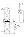
- the figure shows the schematic structure of a column with the first and second stage.
- the figure shows a column (11) in which the first stage (1) and the second stage (2) are arranged one above the other.
- the exhaust gas (4) containing S0 2 and H 2 S is passed horizontally into the first stage (1) and brought into contact with a suspension (5a) containing ZnS0 3 , ZnO and ZnS in countercurrent.
- the following chemical reactions take place, with the required oxygen being removed from the exhaust gas:
- a suspension (8) is obtained which contains ZnS, ZnS0 4 and ZnS0 3 .
- This suspension (8) is removed from the bottom (1b) of the first stage (1) from the column (11).
- a portion (8b) of this suspension (8) is fed to the head (1a) of the first stage (1) via a pump (13) and again brought into contact with the exhaust gas (4) containing SO 2 and H 2 S in countercurrent.
- the other part (8a) of the suspension (8) is removed from the system via the three-way valve (12) and worked up either by adding H 2 S0 4 or Cl 2 .
- the depleted of S0 2 and H 2 S exhaust gas (9) is removed at the top (1a) of the first stage (1) and fed to the second stage (2) above the sump (2b).
- the exhaust gas (9) depleted of SO 2 and H 2 S is mixed with a second suspension (6) containing ZnO and with a third suspension (5b) containing ZnO, ZnS0 3 and ZnS, brought into contact in countercurrent.
- Part of the suspension (5) obtained in the sump (2 b) of the second stage (2) is used as the third suspension (5 b).
- the suspensions (6) and (5b) are mixed with one another via a mixing point (7).
- the pollutants H 2 S and S0 2 react with the ZnO according to the following reaction equations:
- the other part (5a) of the suspension (5) is discharged via the three-way valve (3) and fed into the first stage (1) at the head (1a).
- the clean gas (10) is discharged from the second stage at the head (2a).
- 700 m 3 / h of an exhaust gas (4) which contains 980 mg / Nm 3 dry SO 2 and 300 mg / Nm 3 dry H 2 S, are a first stage (1), which is designed as an ordered wash column, supplied and brought into contact in countercurrent with 5 m 3 / h of a first suspension (5a) containing 62.7 g / l ZnS0 3 , 85.5 g / l ZnO and 0.3 g / l ZnS.
- the average pH is 2.0.
- the sprinkling density in the first stage (1) is 40 m 3 / (m 2 .h).
- This second stage (2) is also designed as an ordered wash column.
- the exhaust gas (9) depleted in SO 2 and H 2 S is in the second stage with 5 m 3 / h of a suspension (6) which contains 117 g / l of ZnO and with 4.8 m 3 / h of a third suspension ( 5 b), which contains 62.7 g / I ZnS0 3 , 85.5 g / I ZnO and 0.3 g / I ZnS and that of the suspension (5) obtained in the sump (2 b) of the second stage (2) is removed, brought into contact in countercurrent.
- the average pH of the second stage is between 5.0 and 5.5.
- the sprinkling density in the second stage (2) is 40 m 3 / (m 2 .h).
Landscapes
- Engineering & Computer Science (AREA)
- Chemical & Material Sciences (AREA)
- Health & Medical Sciences (AREA)
- Biomedical Technology (AREA)
- Environmental & Geological Engineering (AREA)
- Analytical Chemistry (AREA)
- General Chemical & Material Sciences (AREA)
- Oil, Petroleum & Natural Gas (AREA)
- Chemical Kinetics & Catalysis (AREA)
- Treating Waste Gases (AREA)
- Chemical Vapour Deposition (AREA)
- Gas Separation By Absorption (AREA)
Abstract
Description
- Die Erfindung betrifft ein Verfahren zur simultanen Entfernung von S02 und H2S aus Abgasen.
- Werden Braunkohle, Erdgas oder Petrolkoks als Brennstoffe oder Rohstoffe für chemische Prozesse eingesetzt, so entstehen häufig Abgase, die Schwefel in gebundener Form enthalten. So fallen beispielsweise in Kraftwerken bei der Dampferzeugung, in Röstöfen bei der Schwefelsäurefabrikation sowie in Drehrohröfen bei der Herstellung von Titandioxid, Zinksulfid oder Bariumsulfid Abgase mit einer relativ hohen Konzentration an S02 oder auch H2S an, die einen Restgehalt an Sauerstoff enthalten. Zur simultanen Entfernung von S02 und H2S aus den Abgasen werden diese Schadstoffe an Adsorptionskatalysatoren katalytisch zu Schwefel umgesetzt. Dieser Schwefel wird an der Katalysatoroberfläche adsorbiert und anschließend bei einer Heißgasdesorption als Elementarschwefel hoher Reinheit gewonnen. Als Adsorptionskatalysator wird beispielsweise Aluminiumoxid verwendet (Ullmanns Enzyklopädie der technischen Chemie, 4. Auf!., Bd. 2, Seite 614).
- Bei diesem bekannten Verfahren zur simultanen Entfernung von S02 und H2S aus Abgasen ist nachteilig, daß die Stöchiometrie der Reaktionsgleichung

- Der Erfindung liegt daher die Aufgabe zugrunde, ein Verfahren zur simultanen Entfernung von S02 und H2S aus Abgasen zu schaffen, das kostengünstig durchführbar ist und mit welchem die Grenzwerte der TA Luft vom 27.2.1986 für S02 und H2S im Reingas relativ weit unterschritten werden.
- Die der Erfindung zugrundeliegende Aufgabe wird dadurch gelöst, daß das S02 und H2S enthaltende Abgas in einer ersten Stufe mit einer ersten Suspension, die 60 bis 95 g/I ZnS03 und 80 bis 90 g/I ZnO und 0,1 bis 1,0 g/I ZnS enthält, im Gegenstrom in Kontakt gebracht wird, wobei 40 bis 60 Vol-% der im Sumpf der ersten Stufe anfallenden Suspension, die 20 bis 35 g/I ZnS und 130 bis 145 g/I ZnS04 und 0,1 bis 8 g/I ZnS03 enthält, aus dem Sumpf der ersten Stufe abgezogen und erneut kontinuierlich am Kopf der ersten Stufe in die erste Stufe eingespeist werden, daß das in der ersten Stufe von S02 und H2S abgereicherte Abgas am Kopf der ersten Stufe abgezogen und in einer zweiten Stufe mit einer zweiten Suspension, die 80 bis 150 g/I ZnO enthält, und mit einer dritten Suspension, die 60 bis 95 g/I ZnS03 und 80 bis 90 g/I ZnO und 0,1 bis 1,0 g/I ZnS enthält, im Gegenstrom in Kontakt gebracht wird, wobei als dritte Suspension 40 bis 60 Vol-% der im Sumpf der zweiten Stufe anfallenden Suspension, die 60 bis 95 g/I ZnS03 und 80 bis 90 g/I ZnO und 0,1 bis 1,0 g/I ZnS enthält, aus dem Sumpf der zweiten Stufe abgezogen und erneut kontinuierlich am Kopf der zweiten Stufe in die zweite Stufe eingespeist werden, daß als erste Suspension 60 bis 40 Vol-% der im Sumpf der zweiten Stufe anfallenden Suspension am Kopf der ersten Stufe eingespeist werden und daß das Reingas am Kopf der zweiten Stufe abgeführt wird.
- Als erste und zweite Stufe werden Füllkörperkolonnen verwendet. Bei den in der ersten und zweiten Stufe im Kreislauf geführten Suspensionen handelt es sich um wäßrige Suspensionen, deren pH-Werte bei 2,0 bis 5,5 liegen. Es hat sich in überraschender Weise gezeigt, daß mit dem erfindungsgemäßen Verfahren die Schadstoffe H2S und S02 fast vollständig aus Abgasen entfernt werden, auch wenn sie in schwankendem Konzentrationsverhältnis zueinander im Abgas vorhanden sind. Das erfindungsgemäße Verfahren ermöglicht infolge der relativ hohen mittleren Berieselungsdichte von 20 bis 60 m3/(m2.h) in der ersten und zweiten Stufe eine weitgehend quantitative Umsetzung der Reaktionspartner, so daß die Entfernung der Schadstoffe H2S und S02 aus Abgasen kostengünstig durchgeführt wird.
- Eine bevorzugte Ausgestaltung der Erfindung besteht darin, daß als erste Stufe und/oder als zweite Stufe geordnete Waschsäulen verwendet werden. Unter dem Begriff "geordnete Waschsäulen" sind diejenigen Füllkörperkolonnen zu verstehen, in welchen die Füllkörper ihrer geometrischen Form entsprechend nach einem bestimmten System angeordnet sind. Dabei können auch Füllkörper-Packungen, die aus vorgefertigten, geordneten Elementen bestehen, verwendet werden. Werden als erste Stufe und/oder zweite Stufe geordnete Waschsäulen verwendet, so wird der Druckverlust in den einzelnen Stufen in vorteilhafter Weise verkleinert.
- Gemäß einer weiteren bevorzugten Ausgestaltung der Erfindung ist die zweite Stufe auf der ersten Stufe innerhalb einer Trennkolonne angeordnet. Dies hat den Vorteil, daß bei der Anordnung der ersten und zweiten Stufe Rohrleitungen eingespart werden, was zu einer weiteren Reduzierung der Verfahrenskosten führt.
- Nach einer weiteren bevorzugten Ausgestaltung der Erfindung wird ein Teil der im Sumpf der ersten Stufe anfallenden Suspension aus der ersten Stufe abgeführt und mit 48 bis 97%iger H2S04 bis zu einem pH-Wert von 0,6 bis 1,0 versetzt. Dabei entsteht ein Gemisch aus S02 und H2S gemäß den folgenden Reaktionsgleichungen:


- Gemäß einer weiteren bevorzugten Ausgestaltung der Erfindung wird ein Teil der im Sumpf der ersten Stufe anfallenden Suspension aus der ersten Stufe abgeführt und mit Cl2 bis zu einem pH-Wert von 1,3 bis 1,8 versetzt. Dabei laufen die folgenden chemischen Reaktionen ab:


- Der bei der Chlorierung anfallende Schwefel wird anschließend aus der Lösung abfiltriert.
- Der Gegenstand der Erfindung wird nachfolgend anhand der Zeichnung (Figur) näher erläutert.
- Die Figur zeigt den schematischen Aufbau einer Kolonne mit der ersten und zweiten Stufe.
- In der Figur ist eine Kolonne (11) dargestellt, in welcher die erste Stufe (1) und die zweite Stufe (2) übereinander angeordnet sind. Das S02 und H2S enthaltende Abgas (4) wird horizontal in die erste Stufe (1) geleitet und mit einer Suspension (5a), die ZnS03, ZnO und ZnS enthält, im Gegenstrom in Kontakt gebracht. Dabei laufen die folgenden chemischen Reaktionen ab, wobei der benötigte Sauerstoff dem Abgas entnommen wird:


- Der andere Teil (5a) der Suspension (5) wird über den Dreiwegehahn (3) abgeführt und am Kopf (1a) in die erste Stufe (1) eingespeist. Das Reingas (10) wird am Kopf (2a) aus der zweiten Stufe abgeführt.
- Die Erfindung wird nachfolgend anhand eines Beispiels näher beschrieben.
- 700 m3/h eines Abgases (4), das 980 mg/Nm3 tr. S02 und 300 mg/Nm3 tr. H2S enthält, werden einer ersten Stufe (1), die als eine geordnete Waschsäule ausgebildet ist, zugeführt und im Gegenstrom mit 5 m3/h einer ersten Suspension (5a), die 62,7 g/I ZnS03, 85,5 g/I ZnO und 0,3 g/I ZnS enthält, in Kontakt gebracht. In der ersten Stufe (1) beträgt der mittlere pH-Wert 2,0. Die Berieselungsdichte beträgt in der ersten Stufe (1) 40 m3/(m2.h). Von der im Sumpf der ersten Stufe (1) anfallenden Suspension (8), die 34,3 g/I ZnS und 0,9 g/I ZnS03 und 135,9 g/1 ZnS04 enthält, werden 60 Vol-% abgeführt und erneut am Kopf (1a) der ersten Stufe (1) mit dem Abgas im Gegenstrom in Kontakt gebracht. 40 Vol-% der im Sumpf (1b) der ersten Stufe (1) anfallenden Suspension (8) werden aus dem System abgeführt und durch Zugabe von H2S04 aufgearbeitet. Das an S02 und H2S abgereicherte Abgas (9), das einen S02-Gehalt von 850 mg/Nm3 tr. und einen H2S-Gehalt von 200 mg/Nm3 tr. aufweist, wird dem Sumpf (2 b) der zweiten Stufe (2) zugeführt. Diese zweite Stufe (2) ist ebenfalls als geordnete Waschsäule ausgebildet. Das an S02 und H2S abgereicherte Abgas (9) wird in der zweiten Stufe mit 5 m3/h einer Suspension (6), die 117 g/I ZnO enthält und mit 4,8 m3/h einer dritten Suspension (5 b), die 62,7 g/I ZnS03, 85,5 g/I ZnO und 0,3 g/I ZnS enthält und die der im Sumpf (2 b) der zweiten Stufe (2) anfallenden Suspension (5) entnommen wird, im Gegenstrom in Kontakt gebracht. Der mittlere pH-Wert der zweiten Stufe liegt zwischen 5,0 und 5,5. Die Berieselungsdichte in der zweiten Stufe (2) beträgt 40 m3/(m2.h). Die verbleibenden 5 m3/h der im Sumpf (2 b) der zweiten Stufe (2) anfallenden Suspension (5) werden aus der zweiten Stufe (2) abgeführt und als erste Suspension (5 a) in die erste Stufe (1) am Kopf (1 a) eingespeist. Das am Kopf (2a) der zweiten Stufe (2) abgeführte Reingas (10) hat einen S02 -Gehalt von 70 mg/Nm3 tr. und einen H2S-Gehalt von 1 mg/Nm3 tr. (tr = trocken).
- Mit dem erfindungsgemäßen Verfahren werden somit die Grenzwerte der TA Luft vom 27.2.1986 für H2S (5 mg/Nm3) und S02 (500 mg/Nm3) relativ weit unterschritten.
Claims (5)
Applications Claiming Priority (2)
| Application Number | Priority Date | Filing Date | Title |
|---|---|---|---|
| DE4023926 | 1990-07-27 | ||
| DE4023926A DE4023926A1 (de) | 1990-07-27 | 1990-07-27 | Simultane entfernung von so(pfeil abwaerts)2(pfeil abwaerts) und h(pfeil abwaerts)2(pfeil abwaerts)s aus abgasen |
Publications (2)
| Publication Number | Publication Date |
|---|---|
| EP0469659A1 true EP0469659A1 (de) | 1992-02-05 |
| EP0469659B1 EP0469659B1 (de) | 1994-06-08 |
Family
ID=6411161
Family Applications (1)
| Application Number | Title | Priority Date | Filing Date |
|---|---|---|---|
| EP91201757A Expired - Lifetime EP0469659B1 (de) | 1990-07-27 | 1991-07-05 | Simultane Entfernung von SO2 und H2S aus Abgasen |
Country Status (5)
| Country | Link |
|---|---|
| EP (1) | EP0469659B1 (de) |
| AT (1) | ATE106769T1 (de) |
| CA (1) | CA2047660A1 (de) |
| DE (2) | DE4023926A1 (de) |
| ES (1) | ES2055519T3 (de) |
Cited By (3)
| Publication number | Priority date | Publication date | Assignee | Title |
|---|---|---|---|---|
| CN102008886A (zh) * | 2010-11-22 | 2011-04-13 | 浙江双屿实业有限公司 | 氧化锌法湿法湍冲洗涤烟气脱硫装置及其烟气脱硫工艺 |
| CN102716657A (zh) * | 2012-06-13 | 2012-10-10 | 河南豫光锌业有限公司 | 一种适用于锌冶炼系统的氧化锌脱硫方法 |
| US8498237B2 (en) | 2006-01-11 | 2013-07-30 | Qualcomm Incorporated | Methods and apparatus for communicating device capability and/or setup information |
Families Citing this family (1)
| Publication number | Priority date | Publication date | Assignee | Title |
|---|---|---|---|---|
| CN106731632A (zh) * | 2016-12-30 | 2017-05-31 | 云南雄冶科技有限公司 | 一种氧化锌脱除烟气中二氧化硫的装置及其工艺 |
Citations (2)
| Publication number | Priority date | Publication date | Assignee | Title |
|---|---|---|---|---|
| US4276271A (en) * | 1979-02-05 | 1981-06-30 | Combustion Engineering, Inc. | Process for the removal of hydrogen sulfide from gas mixtures |
| US4842843A (en) * | 1987-12-17 | 1989-06-27 | Amoco Corporation | Removal of water vapor diluent after regeneration of metal oxide absorbent to reduce recycle stream |
Family Cites Families (3)
| Publication number | Priority date | Publication date | Assignee | Title |
|---|---|---|---|---|
| US4374105A (en) * | 1979-12-11 | 1983-02-15 | Institute Of Gas Technology | Purification of fuel gases |
| DE3544937A1 (de) * | 1985-12-19 | 1987-06-25 | Kali Chemie Ag | Entschwefelungsverfahren |
| GB8610196D0 (en) * | 1986-04-25 | 1986-05-29 | Ici Plc | Sulphur compounds removal |
-
1990
- 1990-07-27 DE DE4023926A patent/DE4023926A1/de active Granted
-
1991
- 1991-07-05 AT AT91201757T patent/ATE106769T1/de not_active IP Right Cessation
- 1991-07-05 EP EP91201757A patent/EP0469659B1/de not_active Expired - Lifetime
- 1991-07-05 ES ES91201757T patent/ES2055519T3/es not_active Expired - Lifetime
- 1991-07-05 DE DE59101835T patent/DE59101835D1/de not_active Expired - Fee Related
- 1991-07-23 CA CA002047660A patent/CA2047660A1/en not_active Abandoned
Patent Citations (2)
| Publication number | Priority date | Publication date | Assignee | Title |
|---|---|---|---|---|
| US4276271A (en) * | 1979-02-05 | 1981-06-30 | Combustion Engineering, Inc. | Process for the removal of hydrogen sulfide from gas mixtures |
| US4842843A (en) * | 1987-12-17 | 1989-06-27 | Amoco Corporation | Removal of water vapor diluent after regeneration of metal oxide absorbent to reduce recycle stream |
Non-Patent Citations (1)
| Title |
|---|
| J.AIR POLLUTION CONTROL ASSOCIATION vol. 7, no. 2, August 1957, Bruceton,PA.,USA Seiten 109 - 115; J.H.FIELD et al.: "Cost Estimates of Liquid-Scrubbing Processes for Removing of Sulfur Dioxide from Flue Gases" * |
Cited By (18)
| Publication number | Priority date | Publication date | Assignee | Title |
|---|---|---|---|---|
| US8879520B2 (en) | 2006-01-11 | 2014-11-04 | Qualcomm Incorporated | Wireless communication methods and apparatus supporting wireless terminal mode control signaling |
| US8885572B2 (en) | 2006-01-11 | 2014-11-11 | Qualcomm Incorporated | Wireless communication methods and apparatus using beacon signals |
| US9369943B2 (en) | 2006-01-11 | 2016-06-14 | Qualcomm Incorporated | Cognitive communications |
| US8498237B2 (en) | 2006-01-11 | 2013-07-30 | Qualcomm Incorporated | Methods and apparatus for communicating device capability and/or setup information |
| US8504099B2 (en) | 2006-01-11 | 2013-08-06 | Qualcomm Incorporated | Communication methods and apparatus relating to cooperative and non-cooperative modes of operation |
| US8750868B2 (en) | 2006-01-11 | 2014-06-10 | Qualcomm Incorporated | Communication methods and apparatus related to wireless terminal monitoring for and use of beacon signals |
| US8774846B2 (en) | 2006-01-11 | 2014-07-08 | Qualcomm Incorporated | Methods and apparatus relating to wireless terminal beacon signal generation, transmission, and/or use |
| US8804677B2 (en) | 2006-01-11 | 2014-08-12 | Qualcomm Incorporated | Methods and apparatus for establishing communications between devices with differing capabilities |
| US9277481B2 (en) | 2006-01-11 | 2016-03-01 | Qualcomm Incorporated | Wireless communication methods and apparatus supporting different types of wireless communciation approaches |
| US8923317B2 (en) | 2006-01-11 | 2014-12-30 | Qualcomm Incorporated | Wireless device discovery in a wireless peer-to-peer network |
| US8879519B2 (en) | 2006-01-11 | 2014-11-04 | Qualcomm Incorporated | Wireless communication methods and apparatus supporting peer to peer communications |
| US8902865B2 (en) | 2006-01-11 | 2014-12-02 | Qualcomm Incorporated | Wireless communication methods and apparatus supporting multiple modes |
| US8902866B2 (en) | 2006-01-11 | 2014-12-02 | Qualcomm Incorporated | Communication methods and apparatus which may be used in the absence or presence of beacon signals |
| US8902864B2 (en) | 2006-01-11 | 2014-12-02 | Qualcomm Incorporated | Choosing parameters in a peer-to-peer communications system |
| US8902860B2 (en) | 2006-01-11 | 2014-12-02 | Qualcomm Incorporated | Wireless communication methods and apparatus using beacon signals |
| CN102008886A (zh) * | 2010-11-22 | 2011-04-13 | 浙江双屿实业有限公司 | 氧化锌法湿法湍冲洗涤烟气脱硫装置及其烟气脱硫工艺 |
| CN102008886B (zh) * | 2010-11-22 | 2012-07-18 | 浙江双屿实业有限公司 | 氧化锌法湿法湍冲洗涤烟气脱硫装置及其烟气脱硫工艺 |
| CN102716657A (zh) * | 2012-06-13 | 2012-10-10 | 河南豫光锌业有限公司 | 一种适用于锌冶炼系统的氧化锌脱硫方法 |
Also Published As
| Publication number | Publication date |
|---|---|
| CA2047660A1 (en) | 1992-01-28 |
| ES2055519T3 (es) | 1994-08-16 |
| DE4023926A1 (de) | 1992-01-30 |
| DE59101835D1 (de) | 1994-07-14 |
| DE4023926C2 (de) | 1993-06-03 |
| EP0469659B1 (de) | 1994-06-08 |
| ATE106769T1 (de) | 1994-06-15 |
Similar Documents
| Publication | Publication Date | Title |
|---|---|---|
| DE2641230C2 (de) | Verfahren zur Abscheidung und Gewinnung von Quecksilber aus Gasen | |
| DE69001729T2 (de) | Entschwefelung von rauchgas. | |
| DE2259034C3 (de) | Verfahren zum Entfernen von Schwefeldioxid aus Abgasen | |
| DE2462681B1 (de) | Verfahren zum Abscheiden von Stickstoffoxiden aus Abgas | |
| DE2161476A1 (de) | Verfahren zum Entschwefeln von Abgasen unter Bildung von Gips als Nebenprodukt | |
| EP0510600B1 (de) | Verfahren zum Entfernen von Schwefelwasserstoff und/oder Schwefelkohlenstoff aus Abgasen | |
| DE2715778A1 (de) | Verfahren und vorrichtung zum entfernen von gasfoermigen schwefeldioxyd- und chlorbestandteilen aus einem gasstrom | |
| DE3740439C2 (de) | ||
| EP0031793B1 (de) | Verfahren zur Herstellung von Phosphorsäure, bei dem Uran in einer gewinnbaren Form erhalten wird | |
| DE2308783C3 (de) | Verfahren zum Entfernen von Schwefeldioxid aus Abgasen | |
| DE4023926C2 (de) | ||
| DE2201246A1 (de) | Verfahren zur Abwasseraufbereitung bei sulfithaltigen Abwaessern | |
| DE2264097B2 (de) | Verfahren zur Reinigung von Cyanwasserstoff, Schwefelwasserstoff und Ammoniak enthaltendem Gas | |
| EP0166469B1 (de) | Verfahren zur Entfernung von Arsen aus Abfallschwefelsäure | |
| DE1247283B (de) | Verfahren zur Entfernung von Schwefeloxyden aus Abgasen unter Gewinnung von Schwefelsaeure | |
| DE2249874B2 (de) | Verfahren zum Entfernen von Schwefeldioxid aus Verbrennungsabgasen | |
| DE3706533C2 (de) | ||
| DE2502079B2 (de) | Verfahren zum Entfernen von Schwefeldioxid aus Verbrennungsabgasen | |
| DE3735803C2 (de) | Verfahren zum Entfernen des Schwefelgehaltes eines Schwefeldioxid enthaltenden Schwachgases | |
| EP0379016B1 (de) | Verfahren zum thermischen Zersetzen von Metallsulfaten | |
| DE2726257A1 (de) | Verfahren zur entschwefelung von abgasen | |
| DE3507718A1 (de) | Verfahren zur reinigung von rauchgasen | |
| DE2147427C3 (de) | Verfahren zum Reinigen von Schwefeldioxid enthaltenden Abgasen | |
| DE2944754A1 (de) | Verfahren zur regenerierung von verbrauchten schwefeldioxid-schwefeltrioxid- adsorbentien mit schwefelwasserstoff bei gemaessigten temperaturen | |
| EP0228630B1 (de) | Entschwefelungsverfahren |
Legal Events
| Date | Code | Title | Description |
|---|---|---|---|
| PUAI | Public reference made under article 153(3) epc to a published international application that has entered the european phase |
Free format text: ORIGINAL CODE: 0009012 |
|
| AK | Designated contracting states |
Kind code of ref document: A1 Designated state(s): AT BE CH DE DK ES FR GB GR IT LI LU NL SE |
|
| 17P | Request for examination filed |
Effective date: 19920320 |
|
| 17Q | First examination report despatched |
Effective date: 19930803 |
|
| GRAA | (expected) grant |
Free format text: ORIGINAL CODE: 0009210 |
|
| AK | Designated contracting states |
Kind code of ref document: B1 Designated state(s): AT BE CH DE DK ES FR GB GR IT LI LU NL SE |
|
| PG25 | Lapsed in a contracting state [announced via postgrant information from national office to epo] |
Ref country code: NL Effective date: 19940608 Ref country code: GR Free format text: LAPSE BECAUSE OF FAILURE TO SUBMIT A TRANSLATION OF THE DESCRIPTION OR TO PAY THE FEE WITHIN THE PRESCRIBED TIME-LIMIT Effective date: 19940608 Ref country code: DK Effective date: 19940608 Ref country code: BE Effective date: 19940608 |
|
| REF | Corresponds to: |
Ref document number: 106769 Country of ref document: AT Date of ref document: 19940615 Kind code of ref document: T |
|
| PG25 | Lapsed in a contracting state [announced via postgrant information from national office to epo] |
Ref country code: AT Effective date: 19940705 |
|
| REF | Corresponds to: |
Ref document number: 59101835 Country of ref document: DE Date of ref document: 19940714 |
|
| PG25 | Lapsed in a contracting state [announced via postgrant information from national office to epo] |
Ref country code: LU Free format text: LAPSE BECAUSE OF NON-PAYMENT OF DUE FEES Effective date: 19940731 Ref country code: LI Effective date: 19940731 Ref country code: CH Effective date: 19940731 |
|
| REG | Reference to a national code |
Ref country code: ES Ref legal event code: FG2A Ref document number: 2055519 Country of ref document: ES Kind code of ref document: T3 |
|
| ET | Fr: translation filed | ||
| ITF | It: translation for a ep patent filed | ||
| PG25 | Lapsed in a contracting state [announced via postgrant information from national office to epo] |
Ref country code: SE Effective date: 19940908 |
|
| GBT | Gb: translation of ep patent filed (gb section 77(6)(a)/1977) |
Effective date: 19940831 |
|
| NLV1 | Nl: lapsed or annulled due to failure to fulfill the requirements of art. 29p and 29m of the patents act | ||
| REG | Reference to a national code |
Ref country code: CH Ref legal event code: PL |
|
| PLBE | No opposition filed within time limit |
Free format text: ORIGINAL CODE: 0009261 |
|
| STAA | Information on the status of an ep patent application or granted ep patent |
Free format text: STATUS: NO OPPOSITION FILED WITHIN TIME LIMIT |
|
| 26N | No opposition filed | ||
| PGFP | Annual fee paid to national office [announced via postgrant information from national office to epo] |
Ref country code: GB Payment date: 20010614 Year of fee payment: 11 |
|
| PGFP | Annual fee paid to national office [announced via postgrant information from national office to epo] |
Ref country code: FR Payment date: 20010709 Year of fee payment: 11 |
|
| PGFP | Annual fee paid to national office [announced via postgrant information from national office to epo] |
Ref country code: ES Payment date: 20010716 Year of fee payment: 11 |
|
| PGFP | Annual fee paid to national office [announced via postgrant information from national office to epo] |
Ref country code: DE Payment date: 20010920 Year of fee payment: 11 |
|
| REG | Reference to a national code |
Ref country code: GB Ref legal event code: IF02 |
|
| PG25 | Lapsed in a contracting state [announced via postgrant information from national office to epo] |
Ref country code: GB Free format text: LAPSE BECAUSE OF NON-PAYMENT OF DUE FEES Effective date: 20020705 |
|
| PG25 | Lapsed in a contracting state [announced via postgrant information from national office to epo] |
Ref country code: ES Free format text: LAPSE BECAUSE OF NON-PAYMENT OF DUE FEES Effective date: 20020706 |
|
| PG25 | Lapsed in a contracting state [announced via postgrant information from national office to epo] |
Ref country code: DE Free format text: LAPSE BECAUSE OF NON-PAYMENT OF DUE FEES Effective date: 20030201 |
|
| GBPC | Gb: european patent ceased through non-payment of renewal fee |
Effective date: 20020705 |
|
| PG25 | Lapsed in a contracting state [announced via postgrant information from national office to epo] |
Ref country code: FR Free format text: LAPSE BECAUSE OF NON-PAYMENT OF DUE FEES Effective date: 20030331 |
|
| REG | Reference to a national code |
Ref country code: FR Ref legal event code: ST |
|
| REG | Reference to a national code |
Ref country code: ES Ref legal event code: FD2A Effective date: 20030811 |
|
| PG25 | Lapsed in a contracting state [announced via postgrant information from national office to epo] |
Ref country code: IT Free format text: LAPSE BECAUSE OF NON-PAYMENT OF DUE FEES;WARNING: LAPSES OF ITALIAN PATENTS WITH EFFECTIVE DATE BEFORE 2007 MAY HAVE OCCURRED AT ANY TIME BEFORE 2007. THE CORRECT EFFECTIVE DATE MAY BE DIFFERENT FROM THE ONE RECORDED. Effective date: 20050705 |