EP0469780A1 - Ebullition de gaz liquéfié - Google Patents
Ebullition de gaz liquéfié Download PDFInfo
- Publication number
- EP0469780A1 EP0469780A1 EP91306750A EP91306750A EP0469780A1 EP 0469780 A1 EP0469780 A1 EP 0469780A1 EP 91306750 A EP91306750 A EP 91306750A EP 91306750 A EP91306750 A EP 91306750A EP 0469780 A1 EP0469780 A1 EP 0469780A1
- Authority
- EP
- European Patent Office
- Prior art keywords
- liquefied gas
- heat exchange
- passages
- rectification column
- boiling
- Prior art date
- Legal status (The legal status is an assumption and is not a legal conclusion. Google has not performed a legal analysis and makes no representation as to the accuracy of the status listed.)
- Granted
Links
- 238000009835 boiling Methods 0.000 title claims description 66
- IJGRMHOSHXDMSA-UHFFFAOYSA-N Atomic nitrogen Chemical compound N#N IJGRMHOSHXDMSA-UHFFFAOYSA-N 0.000 claims abstract description 85
- MYMOFIZGZYHOMD-UHFFFAOYSA-N Dioxygen Chemical compound O=O MYMOFIZGZYHOMD-UHFFFAOYSA-N 0.000 claims abstract description 76
- 229910052757 nitrogen Inorganic materials 0.000 claims abstract description 43
- 239000011552 falling film Substances 0.000 claims abstract description 12
- 230000005484 gravity Effects 0.000 claims abstract description 5
- 239000007789 gas Substances 0.000 claims description 56
- 239000007788 liquid Substances 0.000 claims description 29
- 239000011248 coating agent Substances 0.000 claims description 23
- 238000000576 coating method Methods 0.000 claims description 23
- 239000012530 fluid Substances 0.000 claims description 18
- 229910052751 metal Inorganic materials 0.000 claims description 18
- 239000002184 metal Substances 0.000 claims description 18
- 230000000694 effects Effects 0.000 claims description 15
- 238000010438 heat treatment Methods 0.000 claims description 13
- 238000000034 method Methods 0.000 claims description 13
- 239000000203 mixture Substances 0.000 claims description 9
- 230000006911 nucleation Effects 0.000 claims description 6
- 238000010899 nucleation Methods 0.000 claims description 6
- 230000015572 biosynthetic process Effects 0.000 claims description 5
- 239000011148 porous material Substances 0.000 claims description 5
- QVGXLLKOCUKJST-UHFFFAOYSA-N atomic oxygen Chemical compound [O] QVGXLLKOCUKJST-UHFFFAOYSA-N 0.000 description 13
- 239000001301 oxygen Substances 0.000 description 13
- 229910052760 oxygen Inorganic materials 0.000 description 13
- 239000000463 material Substances 0.000 description 10
- 239000004033 plastic Substances 0.000 description 10
- 229920003023 plastic Polymers 0.000 description 10
- 239000002245 particle Substances 0.000 description 8
- 239000004411 aluminium Substances 0.000 description 6
- 229910052782 aluminium Inorganic materials 0.000 description 6
- XAGFODPZIPBFFR-UHFFFAOYSA-N aluminium Chemical compound [Al] XAGFODPZIPBFFR-UHFFFAOYSA-N 0.000 description 6
- 238000007789 sealing Methods 0.000 description 6
- 238000000926 separation method Methods 0.000 description 6
- 239000000843 powder Substances 0.000 description 5
- 238000009827 uniform distribution Methods 0.000 description 5
- 238000009826 distribution Methods 0.000 description 4
- 239000010408 film Substances 0.000 description 4
- 229920000728 polyester Polymers 0.000 description 4
- PNEYBMLMFCGWSK-UHFFFAOYSA-N Alumina Chemical compound [O-2].[O-2].[O-2].[Al+3].[Al+3] PNEYBMLMFCGWSK-UHFFFAOYSA-N 0.000 description 3
- RYGMFSIKBFXOCR-UHFFFAOYSA-N Copper Chemical compound [Cu] RYGMFSIKBFXOCR-UHFFFAOYSA-N 0.000 description 3
- 239000000956 alloy Substances 0.000 description 3
- 229910045601 alloy Inorganic materials 0.000 description 3
- 238000005219 brazing Methods 0.000 description 3
- 229910052802 copper Inorganic materials 0.000 description 3
- 239000010949 copper Substances 0.000 description 3
- 238000004519 manufacturing process Methods 0.000 description 3
- 239000002131 composite material Substances 0.000 description 2
- 238000010276 construction Methods 0.000 description 2
- 238000000151 deposition Methods 0.000 description 2
- 238000004821 distillation Methods 0.000 description 2
- 239000001307 helium Substances 0.000 description 2
- 229910052734 helium Inorganic materials 0.000 description 2
- SWQJXJOGLNCZEY-UHFFFAOYSA-N helium atom Chemical compound [He] SWQJXJOGLNCZEY-UHFFFAOYSA-N 0.000 description 2
- 239000001257 hydrogen Substances 0.000 description 2
- 229910052739 hydrogen Inorganic materials 0.000 description 2
- 230000001788 irregular Effects 0.000 description 2
- 150000002739 metals Chemical class 0.000 description 2
- 229910000838 Al alloy Inorganic materials 0.000 description 1
- UFHFLCQGNIYNRP-UHFFFAOYSA-N Hydrogen Chemical compound [H][H] UFHFLCQGNIYNRP-UHFFFAOYSA-N 0.000 description 1
- 230000001668 ameliorated effect Effects 0.000 description 1
- 238000010285 flame spraying Methods 0.000 description 1
- 150000002431 hydrogen Chemical class 0.000 description 1
- 238000007373 indentation Methods 0.000 description 1
- 230000000873 masking effect Effects 0.000 description 1
- 229910001092 metal group alloy Inorganic materials 0.000 description 1
- 150000002829 nitrogen Chemical class 0.000 description 1
- 230000003647 oxidation Effects 0.000 description 1
- 238000007254 oxidation reaction Methods 0.000 description 1
- 238000012856 packing Methods 0.000 description 1
- 238000007750 plasma spraying Methods 0.000 description 1
- 238000005086 pumping Methods 0.000 description 1
- 238000010992 reflux Methods 0.000 description 1
- 125000006850 spacer group Chemical group 0.000 description 1
- 238000005507 spraying Methods 0.000 description 1
- 239000000758 substrate Substances 0.000 description 1
Images

Classifications
-
- F—MECHANICAL ENGINEERING; LIGHTING; HEATING; WEAPONS; BLASTING
- F28—HEAT EXCHANGE IN GENERAL
- F28F—DETAILS OF HEAT-EXCHANGE AND HEAT-TRANSFER APPARATUS, OF GENERAL APPLICATION
- F28F13/00—Arrangements for modifying heat-transfer, e.g. increasing, decreasing
- F28F13/18—Arrangements for modifying heat-transfer, e.g. increasing, decreasing by applying coatings, e.g. radiation-absorbing, radiation-reflecting; by surface treatment, e.g. polishing
- F28F13/185—Heat-exchange surfaces provided with microstructures or with porous coatings
- F28F13/187—Heat-exchange surfaces provided with microstructures or with porous coatings especially adapted for evaporator surfaces or condenser surfaces, e.g. with nucleation sites
-
- B—PERFORMING OPERATIONS; TRANSPORTING
- B01—PHYSICAL OR CHEMICAL PROCESSES OR APPARATUS IN GENERAL
- B01D—SEPARATION
- B01D1/00—Evaporating
-
- B—PERFORMING OPERATIONS; TRANSPORTING
- B01—PHYSICAL OR CHEMICAL PROCESSES OR APPARATUS IN GENERAL
- B01D—SEPARATION
- B01D5/00—Condensation of vapours; Recovering volatile solvents by condensation
- B01D5/0003—Condensation of vapours; Recovering volatile solvents by condensation by using heat-exchange surfaces for indirect contact between gases or vapours and the cooling medium
- B01D5/0015—Plates
-
- B—PERFORMING OPERATIONS; TRANSPORTING
- B01—PHYSICAL OR CHEMICAL PROCESSES OR APPARATUS IN GENERAL
- B01D—SEPARATION
- B01D5/00—Condensation of vapours; Recovering volatile solvents by condensation
- B01D5/0033—Other features
- B01D5/0036—Multiple-effect condensation; Fractional condensation
-
- B—PERFORMING OPERATIONS; TRANSPORTING
- B01—PHYSICAL OR CHEMICAL PROCESSES OR APPARATUS IN GENERAL
- B01D—SEPARATION
- B01D5/00—Condensation of vapours; Recovering volatile solvents by condensation
- B01D5/0078—Condensation of vapours; Recovering volatile solvents by condensation characterised by auxiliary systems or arrangements
- B01D5/0081—Feeding the steam or the vapours
-
- F—MECHANICAL ENGINEERING; LIGHTING; HEATING; WEAPONS; BLASTING
- F25—REFRIGERATION OR COOLING; COMBINED HEATING AND REFRIGERATION SYSTEMS; HEAT PUMP SYSTEMS; MANUFACTURE OR STORAGE OF ICE; LIQUEFACTION SOLIDIFICATION OF GASES
- F25J—LIQUEFACTION, SOLIDIFICATION OR SEPARATION OF GASES OR GASEOUS OR LIQUEFIED GASEOUS MIXTURES BY PRESSURE AND COLD TREATMENT OR BY BRINGING THEM INTO THE SUPERCRITICAL STATE
- F25J3/00—Processes or apparatus for separating the constituents of gaseous or liquefied gaseous mixtures involving the use of liquefaction or solidification
- F25J3/02—Processes or apparatus for separating the constituents of gaseous or liquefied gaseous mixtures involving the use of liquefaction or solidification by rectification, i.e. by continuous interchange of heat and material between a vapour stream and a liquid stream
- F25J3/04—Processes or apparatus for separating the constituents of gaseous or liquefied gaseous mixtures involving the use of liquefaction or solidification by rectification, i.e. by continuous interchange of heat and material between a vapour stream and a liquid stream for air
- F25J3/04406—Processes or apparatus for separating the constituents of gaseous or liquefied gaseous mixtures involving the use of liquefaction or solidification by rectification, i.e. by continuous interchange of heat and material between a vapour stream and a liquid stream for air using a dual pressure main column system
- F25J3/04412—Processes or apparatus for separating the constituents of gaseous or liquefied gaseous mixtures involving the use of liquefaction or solidification by rectification, i.e. by continuous interchange of heat and material between a vapour stream and a liquid stream for air using a dual pressure main column system in a classical double column flowsheet, i.e. with thermal coupling by a main reboiler-condenser in the bottom of low pressure respectively top of high pressure column
-
- F—MECHANICAL ENGINEERING; LIGHTING; HEATING; WEAPONS; BLASTING
- F25—REFRIGERATION OR COOLING; COMBINED HEATING AND REFRIGERATION SYSTEMS; HEAT PUMP SYSTEMS; MANUFACTURE OR STORAGE OF ICE; LIQUEFACTION SOLIDIFICATION OF GASES
- F25J—LIQUEFACTION, SOLIDIFICATION OR SEPARATION OF GASES OR GASEOUS OR LIQUEFIED GASEOUS MIXTURES BY PRESSURE AND COLD TREATMENT OR BY BRINGING THEM INTO THE SUPERCRITICAL STATE
- F25J3/00—Processes or apparatus for separating the constituents of gaseous or liquefied gaseous mixtures involving the use of liquefaction or solidification
- F25J3/02—Processes or apparatus for separating the constituents of gaseous or liquefied gaseous mixtures involving the use of liquefaction or solidification by rectification, i.e. by continuous interchange of heat and material between a vapour stream and a liquid stream
- F25J3/04—Processes or apparatus for separating the constituents of gaseous or liquefied gaseous mixtures involving the use of liquefaction or solidification by rectification, i.e. by continuous interchange of heat and material between a vapour stream and a liquid stream for air
- F25J3/04763—Start-up or control of the process; Details of the apparatus used
- F25J3/04866—Construction and layout of air fractionation equipments, e.g. valves, machines
- F25J3/04872—Vertical layout of cold equipments within in the cold box, e.g. columns, heat exchangers etc.
- F25J3/04884—Arrangement of reboiler-condensers
-
- F—MECHANICAL ENGINEERING; LIGHTING; HEATING; WEAPONS; BLASTING
- F25—REFRIGERATION OR COOLING; COMBINED HEATING AND REFRIGERATION SYSTEMS; HEAT PUMP SYSTEMS; MANUFACTURE OR STORAGE OF ICE; LIQUEFACTION SOLIDIFICATION OF GASES
- F25J—LIQUEFACTION, SOLIDIFICATION OR SEPARATION OF GASES OR GASEOUS OR LIQUEFIED GASEOUS MIXTURES BY PRESSURE AND COLD TREATMENT OR BY BRINGING THEM INTO THE SUPERCRITICAL STATE
- F25J5/00—Arrangements of cold exchangers or cold accumulators in separation or liquefaction plants
- F25J5/002—Arrangements of cold exchangers or cold accumulators in separation or liquefaction plants for continuously recuperating cold, i.e. in a so-called recuperative heat exchanger
- F25J5/005—Arrangements of cold exchangers or cold accumulators in separation or liquefaction plants for continuously recuperating cold, i.e. in a so-called recuperative heat exchanger in a reboiler-condenser, e.g. within a column
-
- F—MECHANICAL ENGINEERING; LIGHTING; HEATING; WEAPONS; BLASTING
- F28—HEAT EXCHANGE IN GENERAL
- F28D—HEAT-EXCHANGE APPARATUS, NOT PROVIDED FOR IN ANOTHER SUBCLASS, IN WHICH THE HEAT-EXCHANGE MEDIA DO NOT COME INTO DIRECT CONTACT
- F28D9/00—Heat-exchange apparatus having stationary plate-like or laminated conduit assemblies for both heat-exchange media, the media being in contact with different sides of a conduit wall
- F28D9/0062—Heat-exchange apparatus having stationary plate-like or laminated conduit assemblies for both heat-exchange media, the media being in contact with different sides of a conduit wall the conduits for one heat-exchange medium being formed by spaced plates with inserted elements
- F28D9/0068—Heat-exchange apparatus having stationary plate-like or laminated conduit assemblies for both heat-exchange media, the media being in contact with different sides of a conduit wall the conduits for one heat-exchange medium being formed by spaced plates with inserted elements with means for changing flow direction of one heat exchange medium, e.g. using deflecting zones
-
- F—MECHANICAL ENGINEERING; LIGHTING; HEATING; WEAPONS; BLASTING
- F25—REFRIGERATION OR COOLING; COMBINED HEATING AND REFRIGERATION SYSTEMS; HEAT PUMP SYSTEMS; MANUFACTURE OR STORAGE OF ICE; LIQUEFACTION SOLIDIFICATION OF GASES
- F25J—LIQUEFACTION, SOLIDIFICATION OR SEPARATION OF GASES OR GASEOUS OR LIQUEFIED GASEOUS MIXTURES BY PRESSURE AND COLD TREATMENT OR BY BRINGING THEM INTO THE SUPERCRITICAL STATE
- F25J2250/00—Details related to the use of reboiler-condensers
- F25J2250/02—Bath type boiler-condenser using thermo-siphon effect, e.g. with natural or forced circulation or pool boiling, i.e. core-in-kettle heat exchanger
-
- F—MECHANICAL ENGINEERING; LIGHTING; HEATING; WEAPONS; BLASTING
- F25—REFRIGERATION OR COOLING; COMBINED HEATING AND REFRIGERATION SYSTEMS; HEAT PUMP SYSTEMS; MANUFACTURE OR STORAGE OF ICE; LIQUEFACTION SOLIDIFICATION OF GASES
- F25J—LIQUEFACTION, SOLIDIFICATION OR SEPARATION OF GASES OR GASEOUS OR LIQUEFIED GASEOUS MIXTURES BY PRESSURE AND COLD TREATMENT OR BY BRINGING THEM INTO THE SUPERCRITICAL STATE
- F25J2250/00—Details related to the use of reboiler-condensers
- F25J2250/04—Down-flowing type boiler-condenser, i.e. with evaporation of a falling liquid film
-
- F—MECHANICAL ENGINEERING; LIGHTING; HEATING; WEAPONS; BLASTING
- F25—REFRIGERATION OR COOLING; COMBINED HEATING AND REFRIGERATION SYSTEMS; HEAT PUMP SYSTEMS; MANUFACTURE OR STORAGE OF ICE; LIQUEFACTION SOLIDIFICATION OF GASES
- F25J—LIQUEFACTION, SOLIDIFICATION OR SEPARATION OF GASES OR GASEOUS OR LIQUEFIED GASEOUS MIXTURES BY PRESSURE AND COLD TREATMENT OR BY BRINGING THEM INTO THE SUPERCRITICAL STATE
- F25J2250/00—Details related to the use of reboiler-condensers
- F25J2250/10—Boiler-condenser with superposed stages
-
- F—MECHANICAL ENGINEERING; LIGHTING; HEATING; WEAPONS; BLASTING
- F25—REFRIGERATION OR COOLING; COMBINED HEATING AND REFRIGERATION SYSTEMS; HEAT PUMP SYSTEMS; MANUFACTURE OR STORAGE OF ICE; LIQUEFACTION SOLIDIFICATION OF GASES
- F25J—LIQUEFACTION, SOLIDIFICATION OR SEPARATION OF GASES OR GASEOUS OR LIQUEFIED GASEOUS MIXTURES BY PRESSURE AND COLD TREATMENT OR BY BRINGING THEM INTO THE SUPERCRITICAL STATE
- F25J2250/00—Details related to the use of reboiler-condensers
- F25J2250/20—Boiler-condenser with multiple exchanger cores in parallel or with multiple re-boiling or condensing streams
-
- F—MECHANICAL ENGINEERING; LIGHTING; HEATING; WEAPONS; BLASTING
- F25—REFRIGERATION OR COOLING; COMBINED HEATING AND REFRIGERATION SYSTEMS; HEAT PUMP SYSTEMS; MANUFACTURE OR STORAGE OF ICE; LIQUEFACTION SOLIDIFICATION OF GASES
- F25J—LIQUEFACTION, SOLIDIFICATION OR SEPARATION OF GASES OR GASEOUS OR LIQUEFIED GASEOUS MIXTURES BY PRESSURE AND COLD TREATMENT OR BY BRINGING THEM INTO THE SUPERCRITICAL STATE
- F25J2290/00—Other details not covered by groups F25J2200/00 - F25J2280/00
- F25J2290/32—Details on header or distribution passages of heat exchangers, e.g. of reboiler-condenser or plate heat exchangers
-
- F—MECHANICAL ENGINEERING; LIGHTING; HEATING; WEAPONS; BLASTING
- F25—REFRIGERATION OR COOLING; COMBINED HEATING AND REFRIGERATION SYSTEMS; HEAT PUMP SYSTEMS; MANUFACTURE OR STORAGE OF ICE; LIQUEFACTION SOLIDIFICATION OF GASES
- F25J—LIQUEFACTION, SOLIDIFICATION OR SEPARATION OF GASES OR GASEOUS OR LIQUEFIED GASEOUS MIXTURES BY PRESSURE AND COLD TREATMENT OR BY BRINGING THEM INTO THE SUPERCRITICAL STATE
- F25J2290/00—Other details not covered by groups F25J2200/00 - F25J2280/00
- F25J2290/44—Particular materials used, e.g. copper, steel or alloys thereof or surface treatments used, e.g. enhanced surface
Definitions
- This invention relates to boiling liquefied gas.
- it relates to boiling liquid oxygen, typically by heat exchange with condensing nitrogen vapour.
- the source of the liquid oxygen may be the lower pressure column of a double rectification column comprising a lower pressure rectification column and a higher pressure rectification column.
- the source of the nitrogen vapour may be the higher pressure column.
- the condenser-reboiler is normally at least partially immersed in a volume of liquid oxygen in a sump at the bottom of the lower pressure column.
- the boiling passages extend vertically from bottom to top of the condenser-reboiler and are open at both ends. Boiling of the liquid oxygen in each boiling passage tends to create a differential pressure between the liquid head in the sump and the height of the liquid in the boiling passages. Accordingly, a positive flow of liquid oxygen into and through the boiling passages is induced. This is referred to in the art as 'thermosiphoning', since it is the heating of the liquid oxygen in the heat exchanger passages that causes the siphoning effect to occur.
- the liquid head is however a source of inefficiency since the liquid oxygen at the level of the inlets to the boiling passages at the bottom of the heat exchanger forming the condenser-reboiler is at a temperature below its boiling point at the prevailing pressure. Accordingly, as the liquid oxygen is urged upwardly through the boiling passages as a result of the thermosiphoning effect, so it is first heated from below its saturation temperature to its saturation temperature, and then superheated to a temperature at which boiling begins. As a result, a "pinch" is created and the temperature difference between the vapour leaving the top of a boiling passage in the heat exchanger (which vapour may have liquid entrained in it) and the temperature of the walls defining the passage is typically in the order of 1.5K.
- the sump of the lower pressure column is typically of a larger diameter than the rest of the column. This enables a larger number of heat exchange units to be accommodated in the sump, and hence enables more efficient boiling to be obtained.
- Another alternative is to conduct some of the reboiling of the liquid oxygen outside the lower pressure column in a separate vessel in which heat exchange units operating on the thermosiphon principle are deployed. Both these practices, however, add considerably to the that capital cost of the air separation plant.
- a method of boiling a liquefied gas comprising creating a falling film of the liquefied gas down each of a multiplicity of first heat transfer surfaces defining a set of first heat exchange passages for boiling the liquefied gas, heating the first surfaces so as to boil some of the descending liquid, allowing unboiled liquefied gas to pass into a volume of the liquefied gas in which are at least partially immersed a multiplicity of second heat transfer surfaces defining a set of second passages for boiling the liquefied gas, causing liquefied gas to flow through the second passages, and heating the second heat transfer surfaces so as to boil at least some of the liquefied gas passing through the second passages.
- the invention also provides apparatus for boiling a liquefied gas, comprising a multiplicity of first heat transfer surfaces defining a set of first heat exchange passages each for boiling a falling film of the liquefied gas, said first passages having outlets arranged to permit in use the flow of unboiled liquid into a vessel adapted to contain a volume of the liquefied gas, means for heating said first heat transfer surfaces so as in operation to boil some of the descending liquid, a multiplicity of second heat transfer surfaces defining a set of second heat exchange passages for the boiling liquefied gas, said second heat exchange passages being adapted for the flow of the liquefied gas therethrough and being disposed such that in use they are at least partially immersed in a volume of liquefied gas in a container, and means for heating the second heat transfer surfaces so as to boil at least some of the liquefied gas passing therethrough.
- the first and second heat transfer surfaces are each heated by a heat exchange fluid.
- the heat exchange fluid is a condensing vapour of different composition from the liquefied gas.
- the heat exchange fluid used to heat the first heat transfer surfaces has the same composition as that used to heat the second heat transfer surfaces, both fluids being taken from the same source.
- first heat exchange passages are arranged in at least one first heat exchanger alternately with passages through which said heat exchange fluid is able to be passed.
- second heat exchange passages are preferably arranged in at least one second heat exchanger alternately with heat exchange passages through which the heat exchange fluid is able to be passed.
- the method and apparatus according to the invention are particularly suitable for boiling liquid oxygen.
- the heat exchange fluid is preferably nitrogen, which is itself preferably at least partially condensed during the heat exchange.
- the source of the liquid oxygen is preferably a liquid-vapour contact means in a rectification column in which air is separated to produce the oxygen.
- the first heat exchange passages are accordingly preferably located below such liquid-vapour contact means so as to enable the liquid oxygen to be fed by gravity to the set of first heat exchange passages from, for example, an intermediate tank.
- the vessel that contains the volume of the liquefied gas is the sump of a lower pressure rectification column forming part of a double rectification column comprising the lower pressure column and a higher pressure column.
- the or each heat exchanger including the set of first heat exchange passages is preferably located in the lower pressure rectification column at a level above the or each heat exchanger that includes the second heat exchange passages, but below the liquid-vapour contact means in the column.
- the flow of liquefied gas through the second heat exchange passages is preferably effected by having each such passage open at its bottom end to the volume of liquefied gas, and maintaining a height of liquefied gas in the container suck that the heating of the second heat transfer surfaces to boil the liquefied gas causes a continuous flow of liquid oxygen through these passages by a thermosiphon effect.
- Each heat transfer surface of an apparatus according to the invention preferably comprises a metal or alloy of relatively high thermal conductivity, such as copper, or aluminium or an alloy based on copper or aluminium.
- Each first heat exchanger surface is preferably provided with cavities, indentations, scratches or other irregularities which provide nucleation sites for the formation of vapour bubbles.
- each such surface comprises a porous metallic coating of the kind in which the pores are open and therefore communicate with one another.
- Such a porous coating encourages a homogeneous distribution of the film of liquefied gas on the surface.
- the coating may be of the same or a different composition from the surface to which it is applied.
- the coating is formed by depositing a mixture of particles of the desired metal or metal alloy and particles of a suitable plastics material (or particles of a performed composite of the metal and the plastics material) onto a substrate so as to form a coating comprising particles of plastics material embedded in the metal.
- the resultant coating is then heated to volatilise the plastics material, thereby removing it and leaving a porous metal coating including a multitude of irregular, interconnected, re-entrant cavities.
- the plastics-metallic coating may be deposited by flame spraying or, preferably, plasma spraying.
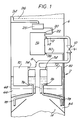
- the double rectification column 2 comprises a higher pressure rectification column 4 of which the top part is shown in Figure 1 and a lower pressure rectification column 6 of which the bottom part is shown in Figure 1.
- the higher pressure column 4 is effective to separate air into nitrogen and oxygen-enriched air fractions.
- a main outlet pipe 8 conducts nitrogen vapour out of the top of the column 4.
- the pipe 8 has a flow control valve 10 located therein and terminates in an inlet 12 to a nitrogen vapour header 14 forming part of a first heat exchanger 16 which in operation is used to boil liquid oxygen by heat exchange with the nitrogen vapour, the nitrogen vapour thereby being at least partially condensed.
- the heat exchanger 16 can thus be described as a condenser-reboiler.
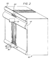
- the heat exchanger 16 is depicted in Figures 2 to 4 of the accompanying drawings, and the ensuing description is with reference, as appropriate, to Figures 2 to 4 as well as Figure 1.
- the main body of the heat exchanger 16 comprises a set of alternate passages for boiling liquid oxygen and condensing nitrogen vapour.
- the passages are defined by a multiplicity of spaced apart parallel plates 18 (see in particular Figures 2 and 3).
- the heat exchanger 16 also has at its top a header 20 for liquid oxygen.
- the header 20 has an inlet 22 which communicates with a tank 25 adapted in use to provide a steady flow of liquid oxygen under gravity to the header 20.
- the tank 25 communicates in turn with a downcomer 24 which provides a passage for liquid oxygen from the bottom of liquid-vapour contact means 26 in the lower pressure column 6 to the tank 25.
- the liquid-vapour contact means typically comprises an array of distillation trays, and the bottom of the liquid-vapour contact means 26 therefore typically comprises the bottom distillation tray. (It is alternatively possible to use a liquid-vapour contact means comprising a structured packing.)
- At the bottom of the heat exchanger 16 is an outlet header 28 for condensed nitrogen vapour.
- the header 28 has an outlet 30 communicating with a pipe 32 which returns the condensed nitrogen vapour to a reservoir 34 in the higher pressure column 4.
- the plates 18 define alternate condensing passages 36 and boiling passages 38.
- the top of each condensing passage 36 communicates with the gaseous nitrogen header 14 and the bottom of each such passage 36 communicates with the liquid nitrogen header 28.
- the top of each boiling passage 38 communicates with the liquid oxygen header 20 while the bottom of each such passage is open so that unboiled liquid oxygen, and oxygen vapour, can pass freely out of the bottom of the heat exchanger 16.
- each condensing passage 36 is provided with fins of heat conductive metal.
- the fins are provided by a corrugated sheet of metal 40 in each passage 36.
- Each sheet 40 is in heat conductive relationship with and joined to the respective surfaces of the plates 18 defining the respective passage 36.
- the sheet 40 is joined to the respective surfaces of the plates 18 defining the passage 36 by vacuum brazing, a technique well known in the art.
- the sheet 40 may be formed with serrations (not shown in the drawings) in it so as to promote good distribution of the fluid in each condensing passage 36.
- the plate surfaces defining each passage 38 preferably have a porous metal coating 42 that encourages a homogeneous distribution of a film of liquid oxygen on the surface.
- the porous coating may generally be of the kind described in our European patent application EP-A-303 493.
- the plates may alternatively be provided with any alternative form of enhanced boiling surface, for example a surface as described in US Reissue Patent No 30 077.
- the coating 42 may be of the same or a different composition from the surface to which it is applied.
- the coating is of aluminium, or copper, or an alloy based on one of these metals.
- the coating is preferably formed by depositing a mixture of particles of the desired metal and particles of a suitable plastics material (or, instead of the mixture, particles of a performed composite of metals and plastics material) onto the respective surfaces of the plates 18 to form a coating comprising particles of plastics material embedded in the metal.
- the resulting coating is then heated to volatilise the plastics material, thereby removing it, and leaving a porous metal coating including a multitude of irregular, interconnected cavities.
- the average pore size of the coating is typically in the range of 15 to 50 microns and the resulting coating typically has a porosity of from 20 to 60%.
- Suitable plastics materials vaporise at temperatures of at least 500°C, and typically from about 500 to 600°C, without leaving a carbonaceous or other residue.
- Preferred plastics materials are polyesters.
- a typical manufacturing procedure for preparing the coating 42 is to mask those surfaces of the plate 18, which are typically of aluminium, in the regions where the porous surface is not needed, that is to say those regions which are to be joined to other members such as support bars and edge bars.
- the unmasked surface is then blasted with a fine grit or shot in order to remove any aluminium oxide on the surface and so as to facilitate formation of a good bond between the plate 18 and the coating 42.
- a mixture of a suitable aluminium alloy powder and polyester powder is then applied using a plasma gun which typically has gas feed lines for gases which can be employed to form a suitable plasma, for example helium and hydrogen, a suitable electrode/nozzle arrangement, and a powder feed line.
- An arc is struck between the electrode and the plate, typically at an amperage of 500 amps, and hydrogen and helium are fed through the electrode into the vicinity of the arc so as to create an intense plasma flame from the gases.
- the powder is fed into the hottest part of the flame.
- the electrical current and the rate of flow of the gases may be controlled by conventional means.
- the plasma gun is preferably mounted on a carriage which is operable to move the gun forwards and backwards and across the plate. Typically, the respective surface of each plate 18 may be coated employing two or three passes of the plasma gun.
- the masking may be removed and the plate placed into an oven, in which the polyester is removed by direct oxidation with air, typically at a temperature in the range 500 to 600°C.
- the plate is then cooled and may be incorporated into the heat exchanger 16. Further information about the manufacture of such surfaces is disclosed in our European patent application EP-A- 303 493.
- the porous coating or surface 42 provides a multiplicity of nucleation sites for the boiling of the liquid oxygen. Its effect therefore is to reduce the amount of superheating of the liquid oxygen that is required to effect boiling in comparison with a conventional thermosiphon boiler. Moreover, the liquid oxygen can be supplied to each boiling passage at substantially its saturation temperature, thereby enabling the amount of heating required to raise the liquid oxygen to its saturation temperature to be kept to a minimum. It is important in the operation of the heat exchanger 16 to ensure that there is a uniform distribution of liquid oxygen to each porous heat transfer surface 42 and to maintain a suitably uniform distribution of liquid film over each surface 42.
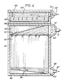
- Figure 4 shows schematically one of the plates 18.
- the forward surface of the plate 18 shown in Figure 4 defines a wall of a condensing passage 36.
- Figure 4 thus in effect shows a condensing passage 36 with a forward plate 18 removed.
- a liquid nitrogen collector 44 which communicates with the header 28 and which extends from one side to the other of the plate 18.
- the collector 44 is provided with two sets of perforate distributor fins 46 and 48 respectively. Both the sets of fins 46 and 48 take the form of corrugated strips of metal (e.g. aluminium).
- the corrugations run at a slight angle to the horizontal, while in the set 48 the corrugations run vertically.
- the arrangement ensures that there is a uniform distribution of liquid nitrogen in the collector and thus there is a smooth flow of liquid nitrogen from the condensing passage into the outlet 30 of the header 28.
- the sets of fins 46 and 48 are preferably permanently joined to the respective plates 18 defining the passage 36, for example by vacuum brazing.
- the fins are defined by a corrugated sheet 40 disposed so that the corrugations run vertically. The top of the sheet 40 terminates well below the top of each associated plate 18.
- a distributor chamber 50 for the nitrogen vapour to be condensed in the passage 38 is located above the fins 40.
- the distributor chamber 50 communicates with the header 14 and extends from one side to the other of the condensing passage 36.
- the chamber 50 is provided with two sets 52 and 54 of perforate distributor fins. Both sets 52 and 54 of fins are typically joined to the respective plates 18 and each comprises strips of corrugated metal, typically aluminium.
- the corrugations run at an angle to the horizontal with the end of each corrugation remote from the header 14 being at a lower level than the opposite end.
- the set 54 of distributor fins have corrugations that run downwards. In operation, the sets 52 and 54 of distributor fins ensure that the gaseous nitrogen is uniformly distributed across the passage 36.
- the passage 36 is provided with sealing bars 56 along its top, side and bottom edges.
- the sealing bars 56 are each joined to the respective surfaces of the plates 18 defining the passage 36, for example by being vacuum brazed thereto.
- each plate 18 extends above the top of its associated condensing passage 36.
- a liquid oxygen distributor 58 which communicates with the liquid oxygen header 20 and which is able to distribute liquid oxygen to the two boiling passages 38 (not shown in Figure 4) which are adjacent the condensing passage 36.
- the distributor 58 takes the form of a chamber which extends across the respective plates 18 from one side to the other and which contains a perforate strip 60 of corrugated metal (of a kind sometimes referred to in the art as "hardway fins”) whose corrugations run horizontally from one side to the other of the distributor chamber 58. In operation, the strip 60 ensure a uniform distributor of liquid oxygen in the distributor chamber 58.
- each plate 18 bounding the chamber 58 (only one such slot 62 is shown in Figure 4) through which liquid oxygen flows out of the chamber 58 into the adjacent boiling passages 38 (not shown in Figure 4).
- sealing bars 56 are also provided at the sides and the top of each condensing passage 36. As previously described, however, each boiling passage 38 is open at its bottom to enable oxygen vapour and residual liquid to form therethrough.
- the oxygen vapour ascends the lower pressure column 6 and comes again into mass transfer relationship with descending liquid in the liquid-vapour contact means 26.
- the residual liquid is collected as will be described below.
- the dimensions of the heat exchanger 16 will typically be related to the size of the lower pressure column 6 and the rate at which the air separation plant is required to produce products. Typically, it may have a height of from 1 to 2 metres and in horizontal cross-section be from 1 to 2 metres square. The distance between each pair of adjacent plates 18 may typically be in the range of 5 to 10mm.
- the liquid oxygen leaving the heat exchanger 16 from the bottom of the boiling passages 38 falls into a volume 66 of liquid oxygen in a sump 68 of the lower pressure column.
- the sump 68 will also receive any overflow from the tank 25.
- Further boiling of the liquid oxygen in the sump 68 is provided by means of heat exchangers 70 and 72 which are partially immersed in the liquid oxygen.
- Both the heat exchangers 70 and 72 are of the plate-fin kind, the plates defining alternate passages for boiling liquid oxygen and for condensing nitrogen vapour (which is used as a heat transfer medium to effect the boiling of the liquid oxygen, the nitrogen itself being condensed).
- the heat exchangers 70 and 72 each have an inlet header 74 for nitrogen vapour communicating with the outlet pipe 8 from the top of the higher pressure column 4.
- the header 74 communicates with each of a multiplicity of nitrogen condensing passages (not shown in Figure 1), each having a nitrogen vapour distribution chamber (not shown) analogous to the chamber 50 shown in Figure 4.
- the nitrogen flows down each of the passages and is at least partially condensed.
- the heat exchangers 70 and 72 can thus be described as condenser-reboilers.
- Each condensing passage is provided with a liquid nitrogen collection chamber (not shown) analogous to the collector 44 shown in Figure 4.
- Each such chamber in the heat exchanger 70 and 72 communicates with an outlet header 76. Both the outlet headers 76 are respectively connected to pipes 78 which conduct the liquid nitrogen condensed in the heat exchanger 70 and 72 into the reservoir 34 in the higher pressure column 4.
- the heat exchanger 70 and 72 have no headering for providing for a flow of oxygen through the boiling passages.
- Each such boiling passage is open both its bottom and its top.
- the head of liquid oxygen in the sump 68 causes liquid oxygen to enter each boiling passage through its bottom and the level of the liquid oxygen within the boiling passages tends to rise to that of the liquid oxygen in the sump 68.
- the oxygen begins to boil and thus the liquid level in the boiling passages would fall were it not for the fact that the liquid oxygen head in the sump 68 causes sufficient liquid to enter the bottom of the boiling passages to restore the liquid oxygen level therein. This effect is known as 'thermosiphoning', as previously mentioned herein.
- the temperature range through which the liquid oxygen needs to be heated in the heat exchanger 70 and 72 before boiling commences is reduced in comparison with a comparable arrangement in which the heat exchanger 16 is omitted.
- the boiling passages in the heat exchanger 70 and 72 are able to be operated with a lower wall temperature than would otherwise be possible.
- the liquid nitrogen may be supplied at its saturation temperature at a lower pressure to the heat exchangers 70 and 72. In effect, therefore, the pressure at the top of the higher pressure column 4 is reduced and thus the amount of work that needs to be performed in compressing the air to be separated is reduced since the air can be compressed to a correspondingly lower pressure.
- the heat exchangers 70 and 72 are typically of conventional construction and manufacture. A typical construction is illustrated in Figure 5 of the drawings.
- the heat exchanger comprises an array of vertical, parallel, plates 80 having heat transfer surfaces.
- the plates 80 define therebetween alternate condensing passages 82 for nitrogen and boiling passages 84 for oxygen. (In Figure 6 one such condensing passage 82 and one such boiling passage 84 are shown.)
- the passages 82 and 84 are each provided with a secondary finned surface to enhance heat transfer. Each such finned surface takes the form of a corrugated sheet 86 of metal; with the corrugations running vertically.
- sealing bars 88 are provided at the sides of the array of plates 80. For ease of illustration, the necessary distributor of gaseous nitrogen and collector of liquid nitrogen associated with the passage 82 are not shown in Figure 5. Similarly, the sealing bars at the top and bottom of each such passage are also omitted from Figure 5.
- thermosiphoning kind Although only one falling film heat exchanger 16 and two heat exchangers (70 and 72) of the thermosiphoning kind are shown, this is primarily for ease of illustration, and generally, large air separation columns will contain an array of each kind of heat exchanger. Typically, it may be arranged that from 20 to 50% of the liquid oxygen may be boiled in falling film heat exchangers, and the remainder by use of heat exchangers that boil the liquid oxygen using a thermosiphon effect. Further, we believe that it is generally possible to include all the necessary heat exchangers within the bottom portion of the lower pressure column 6 without the need to have that part of the lower pressure column 6 of wider diameter than the part thereof that contains the liquid-vapour contact means 26.
- the control valve 10, shown in Figure 1 may be a simple baffle valve set to ensure that there is an adequate level of liquid oxygen in the sump 68 for safe operation.
Landscapes
- Engineering & Computer Science (AREA)
- Chemical & Material Sciences (AREA)
- Physics & Mathematics (AREA)
- Mechanical Engineering (AREA)
- Thermal Sciences (AREA)
- General Engineering & Computer Science (AREA)
- Chemical Kinetics & Catalysis (AREA)
- Crystallography & Structural Chemistry (AREA)
- Separation By Low-Temperature Treatments (AREA)
- Filling Or Discharging Of Gas Storage Vessels (AREA)
Applications Claiming Priority (2)
| Application Number | Priority Date | Filing Date | Title |
|---|---|---|---|
| GB909016766A GB9016766D0 (en) | 1990-07-31 | 1990-07-31 | Boiling liquefied gas |
| GB9016766 | 1990-07-31 |
Publications (2)
| Publication Number | Publication Date |
|---|---|
| EP0469780A1 true EP0469780A1 (fr) | 1992-02-05 |
| EP0469780B1 EP0469780B1 (fr) | 1994-08-31 |
Family
ID=10679926
Family Applications (1)
| Application Number | Title | Priority Date | Filing Date |
|---|---|---|---|
| EP91306750A Expired - Lifetime EP0469780B1 (fr) | 1990-07-31 | 1991-07-24 | Ebullition de gaz liquéfié |
Country Status (8)
| Country | Link |
|---|---|
| EP (1) | EP0469780B1 (fr) |
| KR (1) | KR0185587B1 (fr) |
| CN (1) | CN1058643A (fr) |
| AU (1) | AU8138291A (fr) |
| CA (1) | CA2048254A1 (fr) |
| DE (1) | DE69103709T2 (fr) |
| GB (1) | GB9016766D0 (fr) |
| ZA (1) | ZA915029B (fr) |
Cited By (8)
| Publication number | Priority date | Publication date | Assignee | Title |
|---|---|---|---|---|
| GB2280122A (en) * | 1993-07-19 | 1995-01-25 | Boc Group Plc | Fractional distillation |
| US5438836A (en) * | 1994-08-05 | 1995-08-08 | Praxair Technology, Inc. | Downflow plate and fin heat exchanger for cryogenic rectification |
| DE19605500C1 (de) * | 1996-02-14 | 1997-04-17 | Linde Ag | Vorrichtung und Verfahren zum Verdampfen einer Flüssigkeit |
| US5699671A (en) * | 1996-01-17 | 1997-12-23 | Praxair Technology, Inc. | Downflow shell and tube reboiler-condenser heat exchanger for cryogenic rectification |
| GB2333972A (en) * | 1998-02-09 | 1999-08-11 | Air Liquide | Brazed plates cryogenic condenser |
| EP1094286A1 (fr) * | 1999-10-20 | 2001-04-25 | Linde Aktiengesellschaft | Procédé et dispositif pour la séparation cryogénique des gaz de l'air |
| US6430961B1 (en) | 1999-10-20 | 2002-08-13 | Linde Aktiengesellschaft | Process and device for the low-temperature fractionation of air |
| FR2876441A1 (fr) * | 2004-10-08 | 2006-04-14 | Thermi Consult Soc Par Actions | Condenseur de vapeur a plaques soudees notamment pour tour de condensation et de decantation |
Citations (4)
| Publication number | Priority date | Publication date | Assignee | Title |
|---|---|---|---|---|
| DE1949609A1 (de) * | 1969-10-01 | 1971-04-08 | Linde Ag | Kondensatorverdampfer fuer eine Rektifikationssaeule |
| US4606745A (en) * | 1984-05-30 | 1986-08-19 | Nippon Sanso Kabushiki Kaisha | Condenser-evaporator for large air separation plant |
| US4699209A (en) * | 1986-03-27 | 1987-10-13 | Air Products And Chemicals, Inc. | Heat exchanger design for cryogenic reboiler or condenser service |
| EP0410832A1 (fr) * | 1989-07-28 | 1991-01-30 | L'air Liquide, Societe Anonyme Pour L'etude Et L'exploitation Des Procedes Georges Claude | Appareil de vaporisation-condensation pour double colonne de distillation d'air |
-
1990
- 1990-07-31 GB GB909016766A patent/GB9016766D0/en active Pending
-
1991
- 1991-06-28 ZA ZA915029A patent/ZA915029B/xx unknown
- 1991-07-24 DE DE69103709T patent/DE69103709T2/de not_active Expired - Fee Related
- 1991-07-24 EP EP91306750A patent/EP0469780B1/fr not_active Expired - Lifetime
- 1991-07-26 AU AU81382/91A patent/AU8138291A/en not_active Abandoned
- 1991-07-30 KR KR1019910013093A patent/KR0185587B1/ko not_active Expired - Fee Related
- 1991-07-31 CN CN91105202A patent/CN1058643A/zh active Pending
- 1991-07-31 CA CA002048254A patent/CA2048254A1/fr not_active Abandoned
Patent Citations (4)
| Publication number | Priority date | Publication date | Assignee | Title |
|---|---|---|---|---|
| DE1949609A1 (de) * | 1969-10-01 | 1971-04-08 | Linde Ag | Kondensatorverdampfer fuer eine Rektifikationssaeule |
| US4606745A (en) * | 1984-05-30 | 1986-08-19 | Nippon Sanso Kabushiki Kaisha | Condenser-evaporator for large air separation plant |
| US4699209A (en) * | 1986-03-27 | 1987-10-13 | Air Products And Chemicals, Inc. | Heat exchanger design for cryogenic reboiler or condenser service |
| EP0410832A1 (fr) * | 1989-07-28 | 1991-01-30 | L'air Liquide, Societe Anonyme Pour L'etude Et L'exploitation Des Procedes Georges Claude | Appareil de vaporisation-condensation pour double colonne de distillation d'air |
Cited By (14)
| Publication number | Priority date | Publication date | Assignee | Title |
|---|---|---|---|---|
| GB2280122A (en) * | 1993-07-19 | 1995-01-25 | Boc Group Plc | Fractional distillation |
| GB2280122B (en) * | 1993-07-19 | 1997-03-19 | Boc Group Plc | Fractional distillation |
| US5438836A (en) * | 1994-08-05 | 1995-08-08 | Praxair Technology, Inc. | Downflow plate and fin heat exchanger for cryogenic rectification |
| US5537840A (en) * | 1994-08-05 | 1996-07-23 | Praxair Technology, Inc. | Downflow plate and fin heat exchanger for cryogenic rectification |
| US5724834A (en) * | 1994-08-05 | 1998-03-10 | Praxair Technology, Inc. | Downflow plate and fin heat exchanger for cryogenic rectification |
| US5699671A (en) * | 1996-01-17 | 1997-12-23 | Praxair Technology, Inc. | Downflow shell and tube reboiler-condenser heat exchanger for cryogenic rectification |
| EP0795349A1 (fr) * | 1996-02-14 | 1997-09-17 | Linde Aktiengesellschaft | Dispositif et procédé pour l'évaporation d'un liquide |
| DE19605500C1 (de) * | 1996-02-14 | 1997-04-17 | Linde Ag | Vorrichtung und Verfahren zum Verdampfen einer Flüssigkeit |
| US5901574A (en) * | 1996-02-14 | 1999-05-11 | Linde Aktiengesellschaft | Device and process for evaporating a liquid |
| GB2333972A (en) * | 1998-02-09 | 1999-08-11 | Air Liquide | Brazed plates cryogenic condenser |
| GB2333972B (en) * | 1998-02-09 | 2002-01-30 | Air Liquide | Brazed plates cryogenic condenser |
| EP1094286A1 (fr) * | 1999-10-20 | 2001-04-25 | Linde Aktiengesellschaft | Procédé et dispositif pour la séparation cryogénique des gaz de l'air |
| US6430961B1 (en) | 1999-10-20 | 2002-08-13 | Linde Aktiengesellschaft | Process and device for the low-temperature fractionation of air |
| FR2876441A1 (fr) * | 2004-10-08 | 2006-04-14 | Thermi Consult Soc Par Actions | Condenseur de vapeur a plaques soudees notamment pour tour de condensation et de decantation |
Also Published As
| Publication number | Publication date |
|---|---|
| ZA915029B (en) | 1992-06-24 |
| EP0469780B1 (fr) | 1994-08-31 |
| GB9016766D0 (en) | 1990-09-12 |
| CA2048254A1 (fr) | 1992-02-01 |
| DE69103709T2 (de) | 1994-12-22 |
| KR0185587B1 (ko) | 1999-04-15 |
| KR920002191A (ko) | 1992-02-28 |
| DE69103709D1 (de) | 1994-10-06 |
| CN1058643A (zh) | 1992-02-12 |
| AU8138291A (en) | 1992-02-13 |
Similar Documents
| Publication | Publication Date | Title |
|---|---|---|
| US20100313599A1 (en) | Fin For Heat Exchanger And Heat Exchange Equipped With Such Fins | |
| US4599097A (en) | Process and device for vaporizing a liquid by heat exchange with a second fluid and their application in an air distillation installation | |
| EP0501471A2 (fr) | Procédé d'ébullition et échangeur de chaleur utilisé dans ce procédé | |
| US5144809A (en) | Apparatus for production of nitrogen | |
| EP0275029B1 (fr) | Procédé d'ébullition multi-zone et appareil | |
| US7677300B2 (en) | Method for making brazed heat exchanger and apparatus | |
| US6695043B1 (en) | Falling-film evaporator and corresponding air distillation plants | |
| CN100587382C (zh) | 用于在换热器中蒸发和/或冷凝的方法 | |
| EP0469780B1 (fr) | Ebullition de gaz liquéfié | |
| US4653572A (en) | Dual-zone boiling process | |
| US5868199A (en) | Method and apparatus for reboiling a liquefied gas mixture | |
| CN101280994A (zh) | 低温冷凝及蒸发系统 | |
| US5014773A (en) | Liquefied gas boilers | |
| USRE33026E (en) | Process and device for vaporizing a liquid by heat exchange with a second fluid and their application in an air distillation installation | |
| GB2084308A (en) | Revapourising liquefied gas | |
| US20070028649A1 (en) | Cryogenic air separation main condenser system with enhanced boiling and condensing surfaces | |
| US6393864B1 (en) | Bath reboiler-condenser consisting of brazed plates and its application to an air distillation plant | |
| GB2280122A (en) | Fractional distillation | |
| CN106766673A (zh) | 带有穿孔排放管的冷凝器‑重沸器系统及方法 | |
| JPH09217984A (ja) | 熱交換器と二段蒸留塔 | |
| CN101248324B (zh) | 低温空气分离 | |
| EP0866293A1 (fr) | Rebouilleur-condenseur à courant descendant avec pompage par entraínement à la vapeur | |
| GB2316478A (en) | Liquefaction heat exchanger | |
| CN109107210A (zh) | 精馏设备 | |
| EP1099919A1 (fr) | Wärmetauscher und dephlegmator |
Legal Events
| Date | Code | Title | Description |
|---|---|---|---|
| PUAI | Public reference made under article 153(3) epc to a published international application that has entered the european phase |
Free format text: ORIGINAL CODE: 0009012 |
|
| AK | Designated contracting states |
Kind code of ref document: A1 Designated state(s): DE FR GB IT NL |
|
| 17P | Request for examination filed |
Effective date: 19920803 |
|
| 17Q | First examination report despatched |
Effective date: 19930212 |
|
| GRAA | (expected) grant |
Free format text: ORIGINAL CODE: 0009210 |
|
| ITF | It: translation for a ep patent filed | ||
| AK | Designated contracting states |
Kind code of ref document: B1 Designated state(s): DE FR GB IT NL |
|
| ET | Fr: translation filed | ||
| REF | Corresponds to: |
Ref document number: 69103709 Country of ref document: DE Date of ref document: 19941006 |
|
| PGFP | Annual fee paid to national office [announced via postgrant information from national office to epo] |
Ref country code: NL Payment date: 19950627 Year of fee payment: 5 |
|
| PLBE | No opposition filed within time limit |
Free format text: ORIGINAL CODE: 0009261 |
|
| STAA | Information on the status of an ep patent application or granted ep patent |
Free format text: STATUS: NO OPPOSITION FILED WITHIN TIME LIMIT |
|
| 26N | No opposition filed | ||
| PG25 | Lapsed in a contracting state [announced via postgrant information from national office to epo] |
Ref country code: NL Effective date: 19970201 |
|
| NLV4 | Nl: lapsed or anulled due to non-payment of the annual fee |
Effective date: 19970201 |
|
| PGFP | Annual fee paid to national office [announced via postgrant information from national office to epo] |
Ref country code: FR Payment date: 19980618 Year of fee payment: 8 |
|
| PGFP | Annual fee paid to national office [announced via postgrant information from national office to epo] |
Ref country code: DE Payment date: 19980625 Year of fee payment: 8 |
|
| PGFP | Annual fee paid to national office [announced via postgrant information from national office to epo] |
Ref country code: GB Payment date: 19980626 Year of fee payment: 8 |
|
| PG25 | Lapsed in a contracting state [announced via postgrant information from national office to epo] |
Ref country code: GB Free format text: LAPSE BECAUSE OF NON-PAYMENT OF DUE FEES Effective date: 19990724 |
|
| PG25 | Lapsed in a contracting state [announced via postgrant information from national office to epo] |
Ref country code: FR Free format text: THE PATENT HAS BEEN ANNULLED BY A DECISION OF A NATIONAL AUTHORITY Effective date: 19990731 |
|
| GBPC | Gb: european patent ceased through non-payment of renewal fee |
Effective date: 19990724 |
|
| PG25 | Lapsed in a contracting state [announced via postgrant information from national office to epo] |
Ref country code: DE Free format text: LAPSE BECAUSE OF NON-PAYMENT OF DUE FEES Effective date: 20000503 |
|
| REG | Reference to a national code |
Ref country code: FR Ref legal event code: ST |
|
| PG25 | Lapsed in a contracting state [announced via postgrant information from national office to epo] |
Ref country code: IT Free format text: LAPSE BECAUSE OF NON-PAYMENT OF DUE FEES;WARNING: LAPSES OF ITALIAN PATENTS WITH EFFECTIVE DATE BEFORE 2007 MAY HAVE OCCURRED AT ANY TIME BEFORE 2007. THE CORRECT EFFECTIVE DATE MAY BE DIFFERENT FROM THE ONE RECORDED. Effective date: 20050724 |