EP0469871A1 - Charrue réversible à socs - Google Patents
Charrue réversible à socs Download PDFInfo
- Publication number
- EP0469871A1 EP0469871A1 EP91306996A EP91306996A EP0469871A1 EP 0469871 A1 EP0469871 A1 EP 0469871A1 EP 91306996 A EP91306996 A EP 91306996A EP 91306996 A EP91306996 A EP 91306996A EP 0469871 A1 EP0469871 A1 EP 0469871A1
- Authority
- EP
- European Patent Office
- Prior art keywords
- cylinder
- cross member
- piston
- lower hitch
- piston means
- Prior art date
- Legal status (The legal status is an assumption and is not a legal conclusion. Google has not performed a legal analysis and makes no representation as to the accuracy of the status listed.)
- Withdrawn
Links
- 230000002441 reversible effect Effects 0.000 title claims abstract description 11
- 230000004048 modification Effects 0.000 description 6
- 238000012986 modification Methods 0.000 description 6
- 230000000712 assembly Effects 0.000 description 4
- 238000000429 assembly Methods 0.000 description 4
- 230000009977 dual effect Effects 0.000 description 3
- 239000002184 metal Substances 0.000 description 2
- 230000007935 neutral effect Effects 0.000 description 2
- RNAMYOYQYRYFQY-UHFFFAOYSA-N 2-(4,4-difluoropiperidin-1-yl)-6-methoxy-n-(1-propan-2-ylpiperidin-4-yl)-7-(3-pyrrolidin-1-ylpropoxy)quinazolin-4-amine Chemical compound N1=C(N2CCC(F)(F)CC2)N=C2C=C(OCCCN3CCCC3)C(OC)=CC2=C1NC1CCN(C(C)C)CC1 RNAMYOYQYRYFQY-UHFFFAOYSA-N 0.000 description 1
- 230000003213 activating effect Effects 0.000 description 1
- 230000001681 protective effect Effects 0.000 description 1
Images


Classifications
-
- A—HUMAN NECESSITIES
- A01—AGRICULTURE; FORESTRY; ANIMAL HUSBANDRY; HUNTING; TRAPPING; FISHING
- A01B—SOIL WORKING IN AGRICULTURE OR FORESTRY; PARTS, DETAILS, OR ACCESSORIES OF AGRICULTURAL MACHINES OR IMPLEMENTS, IN GENERAL
- A01B15/00—Elements, tools, or details of ploughs
- A01B15/14—Frames
-
- A—HUMAN NECESSITIES
- A01—AGRICULTURE; FORESTRY; ANIMAL HUSBANDRY; HUNTING; TRAPPING; FISHING
- A01B—SOIL WORKING IN AGRICULTURE OR FORESTRY; PARTS, DETAILS, OR ACCESSORIES OF AGRICULTURAL MACHINES OR IMPLEMENTS, IN GENERAL
- A01B3/00—Ploughs with fixed plough-shares
- A01B3/46—Ploughs supported partly by tractor and partly by their own wheels
- A01B3/462—Alternating ploughs with frame rotating about a vertical axis
Definitions
- This invention relates to plows for tilling the earth and more particularly to a moldboard type plow which is reversible for an improved result.
- Reversible moldboard and disc type plows have been used for some time. They require an implement support which is shiftable to change the angle at which the implement is pulled through the earth as it proceeds back and forth so that the angle for one direction is the same as that for the following opposite direction.
- a reversible plow throws the dirt in the same direction when travelling in opposite directions in a longitudinal path.
- the need for such a plow arises from the necessity to create equal furrows without leaving free spaces and to provide an even, levelled surface.
- Watvedt 4,603,745 and 4,825,955 disclose double plowshares mounted on a plow frame which is rotatable in a vertical plane about a shaft by the action of a pair of hydraulic cylinders and pistons.
- the United States patent to Katayama et al. 4,553,605 discloses link arms that are movable up and down by lift rods operated by hydraulic cylinders for the purpose of tilting the implement.
- a further object is to provide a power operated means for tilting the frame carrying the moldboards in crder to adjust the depth of cut of the bottom of the furrow.
- a further object is to provide a hydraulic hookup for the moldboard shifting cylinders and the frame tilting cylinder(s) in which the cylinders are operated sequentially, instead of simultaneously, thus reducing the hydraulic pressure required for the operation, and in which all cylinders are locked following actuation in order to hold the moldboards in the adjusted plowing position.
- a central moldboard carrying beam that is pivotally mounted in a frame having hitch connections, the beam being connected to trunnion mounted cylinder and piston assemblies that control the travel angle of the moldboards and the attitude or angle of the hitch connections being vertically shiftable by auxiliary cylinder and piston assemblies in order to adjust the tilt of the moldboards.
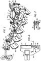
- a frame 10 having a front cross member 11, a rear cross member comprising upper and lower plates 12 and 13, right and left side members 14 and 15 extending perpendicularly rearwardly from the front cross member 11, and inclined side members 16 and 17 extending to the ends of the rear cross member 12 and 13.
- an arcuate plate 20 bridges the sides 14 and 15 for purposes which will be described.
- an upper hitch plate 22 Extending upwardly from the central and forward portion of the front cross member is an upper hitch plate 22, in two parallel sections, and having a hitch pin 23 extending therethrough for the purposes of attaching to the hitch point of the tractor's three-way hitch.
- each lower hitch plate 25 and 26 Spaced at either side of the upper hitch plate 22 are right and left lower hitch plates 25 and 26 each of which comprises a pair of spaced plate side members that are connected to the front cross member 11.
- a cylinder and piston assembly including cylinders 27 and 28, pistons 29 and 30, which are connected to clevises 31 and 32 carrying hitch pins 33 and 34 projecting from the sides of the outer hitch plates where the hitch pin may be received by the lower connections of the three point hitch on the tractor.
- the cylinders 27 and 28 are mounted by pins 35 and 36 across the tops of the spaced hitch plates in order to permit any necessary swinging movement of the cylinder and piston assemblies.
- a replaceable and reversible metal wear plate 36 is mounted at the rear of each of the clevises 31 and 32. This protects the slot in which the pin 33 reciprocates from excessive wear.
- the frame mounts a longitudinal beam which may be in two sections 40 and 41.
- the forward section 40 is received intermediate the upper and lower rear cross members 12 and 13 and connected thereto by a pivot 42 which permits the beam to swing laterally of the frame.
- the forward end of the frame has a ledge plate with upper and lower sections 45, 45 and wear strips 46, 47 which ride on the top and bottom of the arcuate plate 20 previously described, in order to support the forward end of the longitudinal beam.
- a pair of cylinders 50 and 51 are mounted, one on each side of the beam.
- a right cylinder 50 is mounted with its cylinder intermediate the upper and lower portions of the rear cross member 12 and 13 by a pivot or trunnion mounting 52, its piston 53 extending to a pin 54 mounted between a pair of lugs 55 which are in spaced relation from the forward end of the beam.
- the cylinder 51 has a trunnion mounting 56 and a piston 57 which is connected to a pin 58 between lugs 59 on the opposite side of the beam.
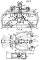
- the forward portion of the longitudinal beam may be angularly shifted from side to side within the frame 10.
- the front and rear portions of the longitudinal beam 40-41 have a series of spaced brackets 60 which are connected to mounting plates 61 for holding a series of spaced moldboards 62.
- the longitudinal beam may be divided into two portions 40 and 41.
- the rear portion 41 of the beam has supports 70 and 71 for a rear wheel beam 72 for carrying a gauge wheel 73.
- Suitable adjusting means 74 are carried in the support 71 in order that the height of the gauge wheel may be adjusted.
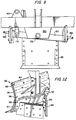
- the moldboards 62 may be made of curved metal frame sections 90 having upper bracket means 91, central bracket means 92 and lower bracket means 93 with protective follower members 94 that aid in the control of the tractor.
- the frame sections 90 are faced with a wear sheet 95 secured by fasteners 96 and holder strip 97 for reducing the wear on the moldboards and the need for frequent replacement.
- Fig. 13 The hydraulic control circuit for the positioning cylinders and tilt cylinders is illustrated in Fig. 13.
- lines 100-101 may connect to the hydraulic control lines of the tractor. These are connected to a double dual lock out box 102.
- line 100 is connected to joints 104 and 105; line 101 is connected to joints 106 and 107.
- Joints 104 is connected to lines 110 and 111 to one side of tilt cylinders 27 and 28.
- Joint 105 is connected to lines 113 and 114 to one side of positioning cylinders 50 and 51.
- tilt cylinders 27 and 28 are connected by lines 115 and 116 to joint 106 and line 101 back to the tractor.
- the return lines 118 and 119 from the positioning cylinders 50 and 51 are connected to the joint 107 and line 120 to the line 101 to the tractor.
- the opening of the circuit will generally unlock the circuit with the less pressure, which is usually the positioning cylinder circuit, permitting movement of these cylinders until the plow beam goes the maximum extent and hits the stop, either on the right or the left side. At this point the pressure build up and causes the tilt cylinders to operate. After all of the hydraulic functions have been completed additional pressure will bleed over to the tractor relief. When the tractor lever is returned to neutral, the double dual lock-out will lock all of the cylinders, preventing them from any movements during the plowing operation.
- the less pressure which is usually the positioning cylinder circuit
- the tractor three-way hitch is generally operated to raise the frame and the beam with the moldboards attached clear of the field until the tractor has turned 180° and is in position to resume plowing in the opposite direction. Then the three-way hitch is lowered in order that plowing in the opposite direction may be done. During the time that the three way hitch is raised the hydraulic circuit may be operated in order to properly position the beam with the moldboards in the proper position for plowing (See Fig. 4) and also to properly position the frame in its appropriately tilted position.
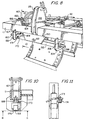
- Figs. 8-11 illustrate a modification of the invention.
- the modification is in the mounting by means of which the height of the left and right hitch pins are controlled.
- the modification includes a hitch plate pivot assembly, as particularly illustrated in Figs. 8 and 9.
- the assembly includes a hitch plate 150 that is mounted on and depends downwardly from the front cross member 11, substantially centrally thereof.
- the hitch plate has a center pivot 152 which supports a hitch bar 153 that is pivotally mounted between left and right lower hitch plates 154 and 155.
- the hitch plates have openings 156 and 157, respectively, for receiving the ends of the hitch bar as it oscillates, the hitch bar carrying left and right lift pins 159 and 160.
- a pair of spaced lugs 162-163 are mounted over an opening 164 on the right side of the front cross member 11 and substantially over the right lower hitch plate 155.
- the lug 162 carries a pivot pin 166 which mounts a cylinder 167 which operates a piston 168 connected to a web 169 of a clevis 170 which engages the hitch bar 153 by means of a pin 171.
- the hitch bar may be caused to pivot about the pivot support 152 in order to raise and lower the right and left lift pins 160 and 159.
- a replacement tee-shaped wear plate 173 is held by a clamp 174 connected to the hitch plate 155 and engaging the clevis 170.
- a hydraulic hookup as indicated on Fig. 14 is provided.
- the hookup includes the lines 100-101 to the tractor disconnects.
- the line 100 is connected to joint 180 and joint 181 which are connected to lines 182 and 183, respectively, to one side of the positioning cylinders and the tilt cylinder.
- the other line 101 is connected to line 184 and line 185 to the other side of the cylinders of the positioning cylinders and the tilt cylinder.
Landscapes
- Life Sciences & Earth Sciences (AREA)
- Engineering & Computer Science (AREA)
- Mechanical Engineering (AREA)
- Soil Sciences (AREA)
- Environmental Sciences (AREA)
- Soil Working Implements (AREA)
- Lifting Devices For Agricultural Implements (AREA)
Applications Claiming Priority (2)
| Application Number | Priority Date | Filing Date | Title |
|---|---|---|---|
| US562026 | 1990-08-02 | ||
| US07/562,026 US5024281A (en) | 1990-08-02 | 1990-08-02 | Reversible moldboard plow |
Publications (1)
| Publication Number | Publication Date |
|---|---|
| EP0469871A1 true EP0469871A1 (fr) | 1992-02-05 |
Family
ID=24244496
Family Applications (1)
| Application Number | Title | Priority Date | Filing Date |
|---|---|---|---|
| EP91306996A Withdrawn EP0469871A1 (fr) | 1990-08-02 | 1991-07-30 | Charrue réversible à socs |
Country Status (3)
| Country | Link |
|---|---|
| US (1) | US5024281A (fr) |
| EP (1) | EP0469871A1 (fr) |
| PL (1) | PL291311A1 (fr) |
Cited By (2)
| Publication number | Priority date | Publication date | Assignee | Title |
|---|---|---|---|---|
| FR2699040A1 (fr) * | 1992-12-14 | 1994-06-17 | Bugnot Ets | Charrue réversible à chassis pivotant perpendiculairement au plan de travail. |
| FR2723812A1 (fr) * | 1994-08-26 | 1996-03-01 | Bugnot Sarl Ets | Charrue reversible a corps de labour symetriques equipes de contre-seps |
Families Citing this family (10)
| Publication number | Priority date | Publication date | Assignee | Title |
|---|---|---|---|---|
| JPH03503239A (ja) * | 1988-11-21 | 1991-07-25 | ワジーム、ミハイロウィッチ マツェプロ | 鋤 |
| US5323862A (en) * | 1991-07-08 | 1994-06-28 | Long Manufacturing N.C., Inc. | Moldboard plow trip |
| US5267618A (en) * | 1991-10-10 | 1993-12-07 | Harrell Danny H | Bidirectional plow with rotatable tool bar |
| DE4139229A1 (de) * | 1991-11-22 | 1993-05-27 | Thrige Agro As | Schwenkpflug |
| WO1993023985A1 (fr) * | 1992-05-27 | 1993-12-09 | Agromet-Famarol S.A. | Charrue orientable |
| US5771979A (en) * | 1994-12-28 | 1998-06-30 | Industrias John Deere, S.A. De C.V. | Bi-directional moldboards supports used in moldboard plows to carry out conservation tillage |
| US5707170A (en) * | 1996-08-28 | 1998-01-13 | Deere & Company | Connector for agricultural tubes and toolbars |
| US9456538B2 (en) * | 2013-10-04 | 2016-10-04 | Deere & Company | Reversible plough |
| US11421397B2 (en) * | 2019-05-02 | 2022-08-23 | Caterpillar Inc. | Wear plate for a blade |
| CN111010892B (zh) * | 2020-01-16 | 2025-04-04 | 李殿奎 | 带减震轮的半悬挂智能翻转犁 |
Citations (8)
| Publication number | Priority date | Publication date | Assignee | Title |
|---|---|---|---|---|
| US3305025A (en) * | 1963-10-23 | 1967-02-21 | Int Harvester Co | Two-way moldboard plow |
| GB1497259A (en) * | 1975-06-19 | 1978-01-05 | Pettit Ltd F | Reversible ground-working implement |
| FR2390079A2 (fr) * | 1973-09-25 | 1978-12-08 | Brousmiche Roger | Charrue reversible a corps unique |
| AU516929B2 (en) * | 1977-08-11 | 1981-07-02 | William Stephen Allen | A reversible disc plough |
| GB2168881A (en) * | 1983-06-28 | 1986-07-02 | Kverneland As | Reversing mechanism |
| WO1988001129A1 (fr) * | 1986-08-12 | 1988-02-25 | Denis Coste | Charrue a corps symetriques |
| US4800963A (en) * | 1986-04-09 | 1989-01-31 | Industrias John Deere, S.A. De C.V. | Bidirectional moldboard plow with moldboard frame including guide member |
| US4869327A (en) * | 1988-07-07 | 1989-09-26 | Korf Alfred W | Reversible one-way disk plow |
Family Cites Families (19)
| Publication number | Priority date | Publication date | Assignee | Title |
|---|---|---|---|---|
| US3126969A (en) * | 1964-03-31 | Moldboard plows | ||
| US1149720A (en) * | 1914-08-10 | 1915-08-10 | Leonard Brown | Reversible gang-plow. |
| US2672801A (en) * | 1950-04-17 | 1954-03-23 | Jr Charles F Barrett | Reversible disk plow |
| US2597079A (en) * | 1950-06-17 | 1952-05-20 | Jr Willard F Dukes | Disk tiller |
| US2724313A (en) * | 1951-06-13 | 1955-11-22 | Int Harvester Co | Two-way disk plow |
| US2764075A (en) * | 1953-03-19 | 1956-09-25 | E L Caldwell & Sons | Reversible plow |
| US2752836A (en) * | 1954-06-22 | 1956-07-03 | John S Pilch | Tractor implement hitch |
| US3042120A (en) * | 1960-02-05 | 1962-07-03 | Towner Mfg Company | Two way plow |
| US3101789A (en) * | 1962-01-02 | 1963-08-27 | Int Harvester Co | Disk plow attachment |
| US3101788A (en) * | 1962-01-02 | 1963-08-27 | Int Harvester Co | Two-way disk plow |
| US3115191A (en) * | 1962-04-16 | 1963-12-24 | Int Harvester Co | Two-way plow with disks for coulters and moldboards |
| CA970204A (en) * | 1972-09-05 | 1975-07-01 | Ralph W. Tuttle | Disc tiller |
| US3995698A (en) * | 1975-07-11 | 1976-12-07 | Tom Holland Nelson | Plow moldboard guard |
| SU640688A1 (ru) * | 1976-06-14 | 1979-01-05 | Всесоюзный Ордена Трудового Красного Знамени Научно-Исследовательский Институт Механизации Сельского Хозяйства | Корпус плуга |
| GB2002211B (en) * | 1977-08-11 | 1982-02-10 | Allen W | Reversible disc plough |
| GB1603204A (en) * | 1978-05-31 | 1981-11-18 | Durkan P J | Three point linkage for agricultural tractors |
| SU812199A1 (ru) * | 1979-07-09 | 1981-03-15 | Всесоюзный Научно-Исследовательскийинститут Защиты Почв Ot Эрозии | Оборотный плуг |
| NO153516C (no) * | 1984-01-18 | 1986-04-09 | Kverneland As | Vende- og innstillingsmekanisme. |
| US4942928A (en) * | 1986-04-09 | 1990-07-24 | Industrias John Deere, S.A. De C.V. | Bidirectional moldboard plow with adjustable tilting mechanism |
-
1990
- 1990-08-02 US US07/562,026 patent/US5024281A/en not_active Expired - Fee Related
-
1991
- 1991-07-30 EP EP91306996A patent/EP0469871A1/fr not_active Withdrawn
- 1991-08-01 PL PL29131191A patent/PL291311A1/xx unknown
Patent Citations (8)
| Publication number | Priority date | Publication date | Assignee | Title |
|---|---|---|---|---|
| US3305025A (en) * | 1963-10-23 | 1967-02-21 | Int Harvester Co | Two-way moldboard plow |
| FR2390079A2 (fr) * | 1973-09-25 | 1978-12-08 | Brousmiche Roger | Charrue reversible a corps unique |
| GB1497259A (en) * | 1975-06-19 | 1978-01-05 | Pettit Ltd F | Reversible ground-working implement |
| AU516929B2 (en) * | 1977-08-11 | 1981-07-02 | William Stephen Allen | A reversible disc plough |
| GB2168881A (en) * | 1983-06-28 | 1986-07-02 | Kverneland As | Reversing mechanism |
| US4800963A (en) * | 1986-04-09 | 1989-01-31 | Industrias John Deere, S.A. De C.V. | Bidirectional moldboard plow with moldboard frame including guide member |
| WO1988001129A1 (fr) * | 1986-08-12 | 1988-02-25 | Denis Coste | Charrue a corps symetriques |
| US4869327A (en) * | 1988-07-07 | 1989-09-26 | Korf Alfred W | Reversible one-way disk plow |
Cited By (3)
| Publication number | Priority date | Publication date | Assignee | Title |
|---|---|---|---|---|
| FR2699040A1 (fr) * | 1992-12-14 | 1994-06-17 | Bugnot Ets | Charrue réversible à chassis pivotant perpendiculairement au plan de travail. |
| EP0603044A1 (fr) * | 1992-12-14 | 1994-06-22 | Etablissements Bugnot | Charrue réversible à châssis pivotant perpendiculairement au plan de travail |
| FR2723812A1 (fr) * | 1994-08-26 | 1996-03-01 | Bugnot Sarl Ets | Charrue reversible a corps de labour symetriques equipes de contre-seps |
Also Published As
| Publication number | Publication date |
|---|---|
| PL291311A1 (en) | 1992-04-06 |
| US5024281A (en) | 1991-06-18 |
Similar Documents
| Publication | Publication Date | Title |
|---|---|---|
| US4186806A (en) | Plow system | |
| US4356645A (en) | Variable wing plow blade and mounting structure therefor | |
| US4259794A (en) | Snowplow | |
| US4249323A (en) | Variable wing plow blade and mounting structure therefor | |
| US6035944A (en) | Hinged plow attachment for wheeled and tracked vehicles | |
| US5535832A (en) | Land leveler and cultivator | |
| US3503456A (en) | Mounting linkage for rippers | |
| US5024281A (en) | Reversible moldboard plow | |
| US4125271A (en) | Tool suspension | |
| US5010961A (en) | Angle-tilt-pitch mechanism for dozer blade | |
| US4418759A (en) | Soil leveling apparatus | |
| US3631931A (en) | Bulldozer | |
| US10893643B2 (en) | Tillage implement | |
| CA1093369A (fr) | Charrue a soc a charriere | |
| GB2119614A (en) | An agricultural implement | |
| US4805322A (en) | Excavating blade assembly | |
| US4221267A (en) | Angle and tilt implement assembly | |
| US3608643A (en) | Grading machines | |
| US4248311A (en) | Side shift blade arrangement | |
| US2942363A (en) | Bulldozer | |
| CA1087440A (fr) | Support pour charrue | |
| US3487884A (en) | Bulldozer assembly | |
| US3731749A (en) | Towed plow | |
| US4942928A (en) | Bidirectional moldboard plow with adjustable tilting mechanism | |
| US5381866A (en) | Multi-share plough |
Legal Events
| Date | Code | Title | Description |
|---|---|---|---|
| PUAI | Public reference made under article 153(3) epc to a published international application that has entered the european phase |
Free format text: ORIGINAL CODE: 0009012 |
|
| AK | Designated contracting states |
Kind code of ref document: A1 Designated state(s): AT BE CH DE DK ES FR GB GR IT LI LU NL SE |
|
| 17P | Request for examination filed |
Effective date: 19920326 |
|
| 17Q | First examination report despatched |
Effective date: 19930716 |
|
| STAA | Information on the status of an ep patent application or granted ep patent |
Free format text: STATUS: THE APPLICATION IS DEEMED TO BE WITHDRAWN |
|
| 18D | Application deemed to be withdrawn |
Effective date: 19940127 |