EP0469882B1 - Appareil de traitement d'images - Google Patents
Appareil de traitement d'images Download PDFInfo
- Publication number
- EP0469882B1 EP0469882B1 EP91307010A EP91307010A EP0469882B1 EP 0469882 B1 EP0469882 B1 EP 0469882B1 EP 91307010 A EP91307010 A EP 91307010A EP 91307010 A EP91307010 A EP 91307010A EP 0469882 B1 EP0469882 B1 EP 0469882B1
- Authority
- EP
- European Patent Office
- Prior art keywords
- pattern information
- binarisation
- image
- pattern
- host computer
- Prior art date
- Legal status (The legal status is an assumption and is not a legal conclusion. Google has not performed a legal analysis and makes no representation as to the accuracy of the status listed.)
- Expired - Lifetime
Links
Images



Classifications
-
- G—PHYSICS
- G06—COMPUTING OR CALCULATING; COUNTING
- G06K—GRAPHICAL DATA READING; PRESENTATION OF DATA; RECORD CARRIERS; HANDLING RECORD CARRIERS
- G06K15/00—Arrangements for producing a permanent visual presentation of the output data, e.g. computer output printers
-
- G—PHYSICS
- G06—COMPUTING OR CALCULATING; COUNTING
- G06V—IMAGE OR VIDEO RECOGNITION OR UNDERSTANDING
- G06V30/00—Character recognition; Recognising digital ink; Document-oriented image-based pattern recognition
- G06V30/10—Character recognition
- G06V30/16—Image preprocessing
- G06V30/162—Quantising the image signal
-
- H—ELECTRICITY
- H04—ELECTRIC COMMUNICATION TECHNIQUE
- H04N—PICTORIAL COMMUNICATION, e.g. TELEVISION
- H04N1/00—Scanning, transmission or reproduction of documents or the like, e.g. facsimile transmission; Details thereof
- H04N1/40—Picture signal circuits
- H04N1/405—Halftoning, i.e. converting the picture signal of a continuous-tone original into a corresponding signal showing only two levels
- H04N1/4055—Halftoning, i.e. converting the picture signal of a continuous-tone original into a corresponding signal showing only two levels producing a clustered dots or a size modulated halftone pattern
-
- G—PHYSICS
- G06—COMPUTING OR CALCULATING; COUNTING
- G06K—GRAPHICAL DATA READING; PRESENTATION OF DATA; RECORD CARRIERS; HANDLING RECORD CARRIERS
- G06K2215/00—Arrangements for producing a permanent visual presentation of the output data
- G06K2215/0082—Architecture adapted for a particular function
- G06K2215/0094—Colour printing
-
- G—PHYSICS
- G06—COMPUTING OR CALCULATING; COUNTING
- G06V—IMAGE OR VIDEO RECOGNITION OR UNDERSTANDING
- G06V30/00—Character recognition; Recognising digital ink; Document-oriented image-based pattern recognition
- G06V30/10—Character recognition
Definitions
- the present invention relates to an image processing apparatus suitable particularly for color printing, wherein input multi-value image data is binarized to output images such as characters, graphics, and the like.
- a pattern necessary for the binarisation process is generated in accordance with color designating information which designates the color of a character or the like.
- a host computer generates a multi-value data representative of gradations of R (red), G (green), and B (blue), or Y (yellow), M (magenta), C (cyan), and K (black), in response to color designating commands.
- the printing apparatus Upon reception of the multi-value data from the host computer, the printing apparatus generates binarization patterns of Y, M, C, and K having the designated gradations, and prints out characters or the like with designated colors.
- US-A-4918622 discloses an image processing arrangement in which a screen handler samples reference patterns to provide a bit-mapped half-tone image pattern.
- image processing apparatus as set out in claim 1.
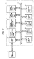
- Fig. 1 is a block diagram showing the circuit arrangement of a printer according to an embodiment of the present invention.
- the printer 2 is connected to a host computer 1.
- the host computer 1 supplies print data, print commands, and the like to the printer 2 which in turn prints a necessary image.
- the printer 2 has the following elements, including: an interface 21 for data transfer to and from the host computer 1, the interface 21 being constituted by a microcomputer having a ROM and RAM; a color information storage 22 for storing information necessary for a color reproduction process; a color reproduction unit 23 for reproducing a color; a binarization pattern storage (RAM) 24 for storing binarization patterns for a binarization process registered upon input of binarization pattern registering commands (color commands) from the host computer in accordance with color information of characters, graphics, or the like to be printed; a binarization pattern storage (ROM) 25 for storing binarization patterns already generated and built in the printer; a data bus 26; a control unit 27 for controlling the entirety of the printer; a command analysis unit 28 for analyzing print data and binarization pattern registering commands supplied from the host computer 1; a dot expand unit 29 for developing a color image data processed by a binarization pattern into dots; an output unit 30 for printing a dot-developed data on a print sheet; and an operating panel
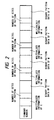
- Fig. 2 shows an example of the binarization pattern registering command (color command) sent from the host computer to the printer.
- the color command is constructed of density information (multi-value levels) and corresponding binarization pattern data for respective colors of C, M, Y, K.
- 64 color commands are used at the initial setting to sequentially output a binarization pattern for each multi-value level.
- a pattern at a desired gradation only may be changed, or a pattern for a desired color only may be changed.
- the size of the pattern may be different from that of a binarization pattern stored in ROM 25. Patterns having different sizes between colors may be registered.
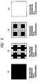
- the pattern size is set to 8 x 8 (pixels) allowing a reproduction of 64 gradations.
- Such binarization patterns are provided for Y, M, C, and K, respectively.
- Fig. 4 shows printed characters "A" using the binarization patterns shown in Fig. 3.
- the gradations of C, M, Y, and K are designated as 100 %, 50 %, 25 %, and 0 %, respectively using the patterns shown in Figs. 3(1) to 3(4).
- the binarization patterns shown in Figs. 3(1) to 3(3) are developed in paint memories of C, M, and Y.
- the resultant character "A" has a mixed color of C, M, and Y. Since the binarization pattern for K is blank, no image is developed in the paint memory of K.
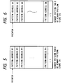
- Fig. 5 shows a binarization pattern table of the binarization pattern storage (RAM) 24.
- the binarization pattern table shown in Fig. 5 is prepared for each C, M, Y, and K.
- the addresses may be overwritten using the binarization pattern registering command (Fig. 2) from the host computer. "-1" in the table shown in Fig. 5 represents the end of the table.
- Fig. 6 shows another binarization table in the binarization pattern storage (ROM) 25.
- the binarization pattern table shown in Fig. 5 is prepared for each C, M, Y, and K.
- Figs. 7 to 10 are flow charts illustrating the procedure of reading a binarization pattern registering command from the host computer, registering the binarization pattern, and selecting the registered binarization pattern (first mode) or the binarization pattern stored in the printer, to print a color image of characters, graphics or the like.
- a binarization registering command is read.
- the binarization registering pattern is analyzed at the command analysis unit 28 to register a binarization pattern.
- a pattern selection mode is selected in response to a mode selection command from the host computer 1.
- color designating information from the host computer is read, the color designating information being, for example, brightness information of designated character color R, G, B.
- a color reproduction process is executed to obtain the density information (multi-value level) of C, M, Y, and K.
- the color reproduction process includes a process of converting brightness information of R, G, and B into density information of C, M, Y, and K, a masking process of eliminating the influence of unnecessary absorption characteristics of tone or ink of C, M, and Y, a process of adjusting contrast, brightens or the like, and other processes.
- step S6 the pattern selection mode selected at step S3 is checked.
- step S7 If the registered pattern selection mode is selected (step S7), then at step S8 the registered binarization pattern 24 is selected. If the stored pattern selection mode is selected (step S10), the stored binarization pattern 25 is selected.
- the dot expand unit develops the image data into dots, respectively for C, M, Y, and K.
- a color image is outputted. The selection between the two modes may be carried out even on the same print sheet.
- step S2 will be detailed with reference to the flow chart of Fig. 8.
- step S21 a pointer is shifted to the top of the binarization pattern table for C in the binarization pattern storage 24.
- the multi-value information (e.g., a value "24" of a multi-value level including 64 levels from “0" to "63") for C is taken out from the binarization pattern registering command.
- step S23 "1" is set to a constant ⁇ .
- step S24 the constant ⁇ is compared with the multi-value information for C taken out at step S22.
- step S25 the value ⁇ and the pointer each are incremented by 1, and thereafter the control returns to step S24.
- step S26 the binarization pattern for C in the binarization pattern registering command is registered in a pattern storage area of the binarization pattern storage 24.
- step S27 the start address of the registered pattern is set to the table.
- step S28 the same processes as at steps S21 to 27 are executed for M, Y, and K.
- step S8 will be detailed with reference to the flow chart shown in Fig. 9.
- step S81 the pointer is shifted to the top of the binarization pattern table for C in the binarization pattern storage 24.
- step S82 there is taken out the multi-value information (e.g., a value "24" of the multi-value level having 64 levels from “0” to "63") obtained at step S5.
- the multi-value information e.g., a value "24" of the multi-value level having 64 levels from “0” to "63
- step S83 "1" is set to a constant ⁇ .
- step S84 the constant ⁇ is compared with the multi-value information for C taken out at step S82.
- step S85 the value ⁇ and the pointer each are incremented by 1, and thereafter the control returns to step S84.
- step S86 the start address of the binarization pattern indicated by the pointer is taken out.
- step S87 the same processes as at steps S81 to 87 are secuted for M, Y, and K.
- step S101 the pointer is shifted to the top of the binarization pattern table for C in the binarization pattern storage 25.
- step S102 there is taken out the multi-value information obtained at step S5.
- step S103 "1" is set to a constant ⁇ .
- step S104 the constant ⁇ is compared with the multi-value information for C taken out at step S102.
- step S105 the value ⁇ and the pointer each are incremented by 1, and thereafter the control returns to step S104.
- step S106 the start address of the binarization pattern indicated by the pointer is taken out.
- step S107 the same processes as at steps S101 to 106 are executed for M, Y, and K.
- this embodiment allows to register a binarization pattern inputted from the host computer.
- One of the registered pattern of the stored pattern built-in the printer is selected to print out a color image of characters, graphics or the like.
- the pattern selection mode is selected by the host computer.
- the pattern selection mode may be selected using the operating panel of the printer.
- the size of the registered binarization pattern or the built-in binarization pattern may be set arbitrarily.
- one of the registered binarization pattern or the built-in binarization pattern for each color and each multi-value level may be selectively used.
- the process time required for printing can be shortened by providing a binarization pattern previously stored. Furthermore, by providing a binarization pattern suitable for a particular printer, it becomes possible to realize a proper color reproduction. Still further, a binarization pattern is inputted from the host computer, resulting in various types of color reproduction.
- the present invention is not limited to the above embodiment, but various modifications are possible without departing from the scope of the present invention.
- a current mode may be displayed on a panel or maybe returned back to the host computer.
- An area for image printing may be designated by a particular mode.
- a particular image area such as an image edge portion may be separated to change a mode only for such an image area.
- a plurality set of binarization pattern data may be stored in ROM 25 or RAM 24 to select one of three modes or more.
Landscapes
- Engineering & Computer Science (AREA)
- Physics & Mathematics (AREA)
- General Physics & Mathematics (AREA)
- Multimedia (AREA)
- Theoretical Computer Science (AREA)
- Computer Vision & Pattern Recognition (AREA)
- General Engineering & Computer Science (AREA)
- Signal Processing (AREA)
- Facsimile Image Signal Circuits (AREA)
- Color, Gradation (AREA)
- Dot-Matrix Printers And Others (AREA)
- Color Image Communication Systems (AREA)
Claims (16)
- Appareil de traitement d'images comprenant :des moyens (21) pour recevoir d'un ordinateur (1) hôte des données à valeurs multiples représentant des valeurs de gradation d'une image ;des moyens (22-28) de conversion pour convertir les données à valeurs multiples recues en des données de pixels binarisées avec des informations de motifs de binarisation représentant des motifs de points dont chacun correspond à une valeur de gradation particulière, de façon que l'image puisse être enregistrée en utilisant un procédé à demi-teintes ;et caractérisé par le fait qu'il comporte des moyens (22) pour stocker des informations de motifs de binarisation qui ont été reçues de l'ordinateur hôte, et en ce que les moyens de conversion sont adaptés à utiliser lesdites informations de motifs de binarisation provenant de l'ordinateur hôte pour générer les données de pixels binarisées.
- Appareil selon la revendication 1, comprenant en outre des seconds moyens (25) de stockage stockant sous forme permanente des secondes informations de motifs de binarisation représentant des motifs de points correspondant à des valeurs de gradation, dans lequel, après que les informations de motifs reçues de l'ordinateur hôte ont été stockées dans les premiers moyens de stockage, ledit appareil peut fonctionner dans un premier mode pendant lequel les données à valeurs multiples reçues sont converties en des données de pixels binarisées en fonction desdites premières informations de motifs, et dans un second mode pendant lequel lesdites données à valeurs multiples fournies en entrées sont converties en données de pixels binarisées en fonction desdites secondes informations de motifs.
- Appareil selon la revendication 2, dans lequel lesdits seconds moyens de stockage sont une mémcire morte.
- Appareil selon la revendication 2 ou la revendication 3, comprenant en outre des moyens pour sélectionner manuellement l'un desdits premier et second modes.
- Appareil selon la revendication 2 ou la revendication 3, comprenant en outre des moyens pour sélectionner l'un desdits premier et second modes en fonction d'un ordre envoyé par ledit ordinateur hôte.
- Appareil selon la revendication 2, dans lequel lesdits premiers moyens de stockage sont conçus pour stocker lesdites premières informations de motifs ayant une taille de motif différente de celle desdites secondes informations de motifs stockées dans lesdits seconds moyens de stockage.
- Appareil selon la revendication 2 ou l'une quelconque des revendications 3 à 6 lorsqu'elles dépendent de la revendication 2, comprenant en outre des moyens d'affichage pour afficher un mode courant.
- Appareil selon la revendication 2, ou selon l'une quelconque des revendications 3 à 7 lorsqu'elles dépendent de la revendication 2, dans lequel ledit appareil est conçu pour traiter une image d'une zone prédéterminée dans un mode sélectionné.
- Appareil selon la revendication 8, dans lequel ladite zone prédéterminée ou ledit mode particulier peuvent être désignés par un opérateur.
- Appareil selon la revendication 9, comprenant en outre des moyens pour détecter, en tant que ladite zone prédéterminée, une partie de bord d'une image devant être fournie en sortie.
- Appareil selon l'une quelconque des revendications précédentes, dans lequel lesdits premiers moyens de stockage sont conçus pour stocker lesdites premières informations de motifs pour des ccmposantes de couleurs.
- Appareil selon la revendication 11, dans lequel ledit appareil est conçu pour stocker lesdites premières informations dans lesquelles chaque couleur a une taille de motif différente.
- Appareil selon l'une quelconque des revendications précédentes, et comprenant en outre des moyens (30) pour fournir en sortie une image sur la base des données de pixels binarisées.
- Procédé de traitement d'images dans lequel un ordinateur (1) hôte envoie des données à valeurs multiples représentant des valeurs de gradation à un appareil (2) de traitement d'images qui convertit les données à valeurs multiples en données de pixels binarisées et fournit en sortie les données de pixels binarisées sous la forme d'une image en demi-teintes, et caractérisé en ce que l'ordinateur envoie tout d'abord des informations de motifs de binarisation représentant des motifs de points correspondant à des valeurs de gradation, l'appareil de traitement d'images stocke (S2) les informations de motifs de binarisation, lit (S4) les données à valeurs multiples envoyées par l'ordinateur hôte, et effectue un traitement (S5) de reproduction sur les données à valeurs multiples reçues en utilisant les informations de motifs de binarisation stockées pour générer des données de pixels binarisées, et fournit en sortie (S12) les données de pixels binarisées.
- Procédé selon la revendication 14, dans lequel l'appareil de traitement d'images comporte une mémoire (25) stockant un second ensemble d'informations de motifs de binarisation différentes des informations de motifs de binarisation envoyées par l'ordinateur, et dans lequel une sélection (S6) est faite de façon que le traitement de reproduction soit effectué en utilisant soit les informations de motifs de binarisation initialement envoyées par l'ordinateur hôte, soit les secondes informations de motifs de binarisation.
- Procédé selon la revendication 15, dans lequel les données à valeurs multiples représentent une image en couleurs et les valeurs de gradation représentent différentes composantes de couleurs.
Applications Claiming Priority (2)
| Application Number | Priority Date | Filing Date | Title |
|---|---|---|---|
| JP206551/90 | 1990-08-03 | ||
| JP2206551A JPH0490669A (ja) | 1990-08-03 | 1990-08-03 | 印刷装置 |
Publications (3)
| Publication Number | Publication Date |
|---|---|
| EP0469882A2 EP0469882A2 (fr) | 1992-02-05 |
| EP0469882A3 EP0469882A3 (en) | 1993-02-24 |
| EP0469882B1 true EP0469882B1 (fr) | 1996-11-20 |
Family
ID=16525263
Family Applications (1)
| Application Number | Title | Priority Date | Filing Date |
|---|---|---|---|
| EP91307010A Expired - Lifetime EP0469882B1 (fr) | 1990-08-03 | 1991-07-31 | Appareil de traitement d'images |
Country Status (4)
| Country | Link |
|---|---|
| US (1) | US5475496A (fr) |
| EP (1) | EP0469882B1 (fr) |
| JP (1) | JPH0490669A (fr) |
| DE (1) | DE69123196T2 (fr) |
Families Citing this family (11)
| Publication number | Priority date | Publication date | Assignee | Title |
|---|---|---|---|---|
| US6359695B1 (en) | 1992-02-26 | 2002-03-19 | Canon Kabushiki Kaisha | Repeated image forming apparatus with neighboring image boundary gradiation correction |
| DE69326660T2 (de) | 1992-07-31 | 2000-04-06 | Canon K.K. | Bildverarbeitungsverfahren und -gerät |
| US5457772A (en) * | 1992-10-13 | 1995-10-10 | Hewlett-Packard Company | Method to convert bitmaps to monochrome data |
| JP2897599B2 (ja) * | 1993-06-23 | 1999-05-31 | 松下電器産業株式会社 | 画像形成装置 |
| US6433884B1 (en) * | 1993-10-29 | 2002-08-13 | Ricoh Company, Ltd. | Apparatus for determining priority of print jobs in a printer system |
| JP3335009B2 (ja) * | 1994-09-08 | 2002-10-15 | キヤノン株式会社 | 画像処理方法及び画像処理装置 |
| US5726778A (en) * | 1994-09-16 | 1998-03-10 | Canon Kabushiki Kaisha | Image processing apparatus with color-space conversion |
| JP3359234B2 (ja) * | 1996-07-31 | 2002-12-24 | キヤノン株式会社 | 画像処理装置及び方法 |
| JP2003046783A (ja) * | 2001-08-02 | 2003-02-14 | Fujitsu Ltd | スムージング方法及びスムージング回路 |
| JP3994984B2 (ja) * | 2004-05-06 | 2007-10-24 | コニカミノルタビジネステクノロジーズ株式会社 | プリント支援モジュール、記録媒体及びプリントジョブ発行方法 |
| US10922801B2 (en) | 2017-07-19 | 2021-02-16 | Lockheed Martin Corporation | Channel-based binarization of color |
Family Cites Families (15)
| Publication number | Priority date | Publication date | Assignee | Title |
|---|---|---|---|---|
| DE1597773C3 (de) * | 1967-08-26 | 1974-09-19 | Dr.-Ing. Rudolf Hell Gmbh, 2300 Kiel | Verfahren zum Setzen gerasteter Halbtonbilder |
| US4005475A (en) * | 1972-06-02 | 1977-01-25 | Dr. -Ing. Rudolf Hell Gmbh | Method for improving sharpness when recording half-tone pictures by modulating a sharpness signal |
| US4004079A (en) * | 1975-11-14 | 1977-01-18 | Optronics International, Inc. | Method and apparatus for dual resolution photographic reproduction of line and continuous tone graphic materials |
| US4084196A (en) * | 1977-01-31 | 1978-04-11 | Dacom, Inc. | Electronic half-tone generating means for facsimile reproduction system |
| JPS58157255A (ja) * | 1982-03-13 | 1983-09-19 | Dainippon Screen Mfg Co Ltd | 画像走査記録方法 |
| JPS59161981A (ja) * | 1983-03-06 | 1984-09-12 | Canon Inc | 画像処理装置 |
| FR2542540B1 (fr) * | 1983-03-08 | 1989-02-10 | Canon Kk | Systeme de traitement d'images |
| DE3444366C3 (de) * | 1983-12-09 | 1994-12-22 | Canon Kk | Bildverarbeitungseinrichtung |
| US4724446A (en) * | 1985-01-31 | 1988-02-09 | Kabushiki Kaisha Toshiba | Thermal transfer printing apparatus |
| JPS63296952A (ja) * | 1987-05-29 | 1988-12-05 | Ricoh Co Ltd | プリンタ |
| JP2774501B2 (ja) * | 1987-11-05 | 1998-07-09 | 株式会社リコー | カラー画像の多値化階調処理方法 |
| EP0317268B1 (fr) * | 1987-11-16 | 1997-07-23 | Canon Kabushiki Kaisha | Appareil d'enregistrement d'images |
| US4918622A (en) * | 1988-11-16 | 1990-04-17 | Eastman Kodak Company | Electronic graphic arts screener |
| US4878063A (en) * | 1988-12-05 | 1989-10-31 | Eastman Kodak Company | Multicolor printing apparatus and method having vernier detection/correction system for adjusting color separation planes |
| US5105266A (en) * | 1989-11-30 | 1992-04-14 | Eastman Kodak Company | Single pass color substitution |
-
1990
- 1990-08-03 JP JP2206551A patent/JPH0490669A/ja active Pending
-
1991
- 1991-07-31 DE DE69123196T patent/DE69123196T2/de not_active Expired - Fee Related
- 1991-07-31 EP EP91307010A patent/EP0469882B1/fr not_active Expired - Lifetime
-
1993
- 1993-08-23 US US08/110,767 patent/US5475496A/en not_active Expired - Lifetime
Also Published As
| Publication number | Publication date |
|---|---|
| US5475496A (en) | 1995-12-12 |
| JPH0490669A (ja) | 1992-03-24 |
| DE69123196T2 (de) | 1997-04-03 |
| EP0469882A2 (fr) | 1992-02-05 |
| DE69123196D1 (de) | 1997-01-02 |
| EP0469882A3 (en) | 1993-02-24 |
Similar Documents
| Publication | Publication Date | Title |
|---|---|---|
| EP0706285B1 (fr) | Appareil et procédé de traitement d'images | |
| JP3869910B2 (ja) | 画像処理方法及び装置及び記憶媒体 | |
| EP0606781B1 (fr) | Procédé et appareil pour le traitement des images en couleur | |
| EP0720352A1 (fr) | Procédé sélectif de correction de couleurs | |
| US5475496A (en) | Image processing apparatus for binarizing multi-value image data | |
| JPH10166664A (ja) | カラー印刷装置 | |
| JPH04296167A (ja) | デジタル中間調印刷装置 | |
| EP0457572B1 (fr) | Procédé et appareil pour la sortie de données d'impression | |
| EP0783226B1 (fr) | Appareil et procédé de traitement d'image | |
| US6351263B1 (en) | Image processor which manually and independently designates processing parameters for character data and image data | |
| EP0686945A2 (fr) | Méthode et appareil de traitement d'images | |
| US7092120B2 (en) | Image transformation apparatus and image transformation program storage medium | |
| EP0481375B1 (fr) | Appareil pour la séparation des couleurs d'une image | |
| EP0473389B1 (fr) | Procédé et dispositif de traitement d'image | |
| EP0582421B1 (fr) | Dispositif de traitement des images | |
| JPH0659657A (ja) | 画像処理装置 | |
| US5051820A (en) | Color image recording apparatus capable of recording color gradation pattern | |
| US5323487A (en) | Printer | |
| JP2911539B2 (ja) | 記録装置 | |
| US6980324B1 (en) | Apparatus and method for generating multicolor image | |
| JPH10138567A (ja) | 文字色設定装置 | |
| JPS62150478A (ja) | 画像情報処理装置 | |
| JPH0787318A (ja) | 画像処理装置及び画像形成装置 | |
| JPH0734577B2 (ja) | カラー画像処理装置 | |
| JPH06253160A (ja) | デジタルカラー画像形成装置 |
Legal Events
| Date | Code | Title | Description |
|---|---|---|---|
| PUAI | Public reference made under article 153(3) epc to a published international application that has entered the european phase |
Free format text: ORIGINAL CODE: 0009012 |
|
| AK | Designated contracting states |
Kind code of ref document: A2 Designated state(s): DE FR GB |
|
| PUAL | Search report despatched |
Free format text: ORIGINAL CODE: 0009013 |
|
| AK | Designated contracting states |
Kind code of ref document: A3 Designated state(s): DE FR GB |
|
| 17P | Request for examination filed |
Effective date: 19930709 |
|
| 17Q | First examination report despatched |
Effective date: 19950508 |
|
| GRAG | Despatch of communication of intention to grant |
Free format text: ORIGINAL CODE: EPIDOS AGRA |
|
| GRAH | Despatch of communication of intention to grant a patent |
Free format text: ORIGINAL CODE: EPIDOS IGRA |
|
| GRAH | Despatch of communication of intention to grant a patent |
Free format text: ORIGINAL CODE: EPIDOS IGRA |
|
| GRAA | (expected) grant |
Free format text: ORIGINAL CODE: 0009210 |
|
| AK | Designated contracting states |
Kind code of ref document: B1 Designated state(s): DE FR GB |
|
| REF | Corresponds to: |
Ref document number: 69123196 Country of ref document: DE Date of ref document: 19970102 |
|
| ET | Fr: translation filed | ||
| PLBE | No opposition filed within time limit |
Free format text: ORIGINAL CODE: 0009261 |
|
| STAA | Information on the status of an ep patent application or granted ep patent |
Free format text: STATUS: NO OPPOSITION FILED WITHIN TIME LIMIT |
|
| 26N | No opposition filed | ||
| REG | Reference to a national code |
Ref country code: GB Ref legal event code: IF02 |
|
| PGFP | Annual fee paid to national office [announced via postgrant information from national office to epo] |
Ref country code: FR Payment date: 20090722 Year of fee payment: 19 |
|
| PGFP | Annual fee paid to national office [announced via postgrant information from national office to epo] |
Ref country code: DE Payment date: 20090731 Year of fee payment: 19 Ref country code: GB Payment date: 20090731 Year of fee payment: 19 |
|
| GBPC | Gb: european patent ceased through non-payment of renewal fee |
Effective date: 20100731 |
|
| REG | Reference to a national code |
Ref country code: FR Ref legal event code: ST Effective date: 20110331 |
|
| PG25 | Lapsed in a contracting state [announced via postgrant information from national office to epo] |
Ref country code: DE Free format text: LAPSE BECAUSE OF NON-PAYMENT OF DUE FEES Effective date: 20110201 |
|
| REG | Reference to a national code |
Ref country code: DE Ref legal event code: R119 Ref document number: 69123196 Country of ref document: DE Effective date: 20110201 |
|
| PG25 | Lapsed in a contracting state [announced via postgrant information from national office to epo] |
Ref country code: FR Free format text: LAPSE BECAUSE OF NON-PAYMENT OF DUE FEES Effective date: 20100802 |
|
| PG25 | Lapsed in a contracting state [announced via postgrant information from national office to epo] |
Ref country code: GB Free format text: LAPSE BECAUSE OF NON-PAYMENT OF DUE FEES Effective date: 20100731 |