EP0469902A2 - Entwicklungsvorrichtung - Google Patents
Entwicklungsvorrichtung Download PDFInfo
- Publication number
- EP0469902A2 EP0469902A2 EP91307063A EP91307063A EP0469902A2 EP 0469902 A2 EP0469902 A2 EP 0469902A2 EP 91307063 A EP91307063 A EP 91307063A EP 91307063 A EP91307063 A EP 91307063A EP 0469902 A2 EP0469902 A2 EP 0469902A2
- Authority
- EP
- European Patent Office
- Prior art keywords
- toner
- developing roller
- porous plate
- developing device
- developing
- Prior art date
- Legal status (The legal status is an assumption and is not a legal conclusion. Google has not performed a legal analysis and makes no representation as to the accuracy of the status listed.)
- Ceased
Links
Images






Classifications
-
- G—PHYSICS
- G03—PHOTOGRAPHY; CINEMATOGRAPHY; ANALOGOUS TECHNIQUES USING WAVES OTHER THAN OPTICAL WAVES; ELECTROGRAPHY; HOLOGRAPHY
- G03G—ELECTROGRAPHY; ELECTROPHOTOGRAPHY; MAGNETOGRAPHY
- G03G15/00—Apparatus for electrographic processes using a charge pattern
- G03G15/06—Apparatus for electrographic processes using a charge pattern for developing
- G03G15/08—Apparatus for electrographic processes using a charge pattern for developing using a solid developer, e.g. powder developer
- G03G15/0806—Apparatus for electrographic processes using a charge pattern for developing using a solid developer, e.g. powder developer on a donor element, e.g. belt, roller
-
- G—PHYSICS
- G03—PHOTOGRAPHY; CINEMATOGRAPHY; ANALOGOUS TECHNIQUES USING WAVES OTHER THAN OPTICAL WAVES; ELECTROGRAPHY; HOLOGRAPHY
- G03G—ELECTROGRAPHY; ELECTROPHOTOGRAPHY; MAGNETOGRAPHY
- G03G15/00—Apparatus for electrographic processes using a charge pattern
- G03G15/06—Apparatus for electrographic processes using a charge pattern for developing
- G03G15/08—Apparatus for electrographic processes using a charge pattern for developing using a solid developer, e.g. powder developer
- G03G15/0822—Arrangements for preparing, mixing, supplying or dispensing developer
- G03G15/0877—Arrangements for metering and dispensing developer from a developer cartridge into the development unit
-
- G—PHYSICS
- G03—PHOTOGRAPHY; CINEMATOGRAPHY; ANALOGOUS TECHNIQUES USING WAVES OTHER THAN OPTICAL WAVES; ELECTROGRAPHY; HOLOGRAPHY
- G03G—ELECTROGRAPHY; ELECTROPHOTOGRAPHY; MAGNETOGRAPHY
- G03G15/00—Apparatus for electrographic processes using a charge pattern
- G03G15/06—Apparatus for electrographic processes using a charge pattern for developing
- G03G15/08—Apparatus for electrographic processes using a charge pattern for developing using a solid developer, e.g. powder developer
- G03G15/0822—Arrangements for preparing, mixing, supplying or dispensing developer
- G03G15/0887—Arrangements for conveying and conditioning developer in the developing unit, e.g. agitating, removing impurities or humidity
-
- G—PHYSICS
- G03—PHOTOGRAPHY; CINEMATOGRAPHY; ANALOGOUS TECHNIQUES USING WAVES OTHER THAN OPTICAL WAVES; ELECTROGRAPHY; HOLOGRAPHY
- G03G—ELECTROGRAPHY; ELECTROPHOTOGRAPHY; MAGNETOGRAPHY
- G03G2215/00—Apparatus for electrophotographic processes
- G03G2215/06—Developing structures, details
- G03G2215/0602—Developer
- G03G2215/0604—Developer solid type
- G03G2215/0614—Developer solid type one-component
-
- G—PHYSICS
- G03—PHOTOGRAPHY; CINEMATOGRAPHY; ANALOGOUS TECHNIQUES USING WAVES OTHER THAN OPTICAL WAVES; ELECTROGRAPHY; HOLOGRAPHY
- G03G—ELECTROGRAPHY; ELECTROPHOTOGRAPHY; MAGNETOGRAPHY
- G03G2215/00—Apparatus for electrophotographic processes
- G03G2215/06—Developing structures, details
- G03G2215/0634—Developing device
- G03G2215/0636—Specific type of dry developer device
Definitions
- the present invention relates to a developing device used in electrophotographic printers, and more particularly to a developing device for developing a latent image formed on a photosensitive drum with a single-component developer.
- a latent image formed on a photosensitive drum is developed by a developing device.
- a two-component developer including a toner and a carrier or a single-component developer including a toner alone is used for a developer.
- a single-component developer is preferred to the two-component developer because of the non-necessity of adjusting the mixing ratio of toner and carrier, and the non-possibility of the toner being unfavorably influenced by the deteriorating carrier.
- a developing device using a single-component developer is equipped with a developing roller for feeding a toner charged with a predetermined polarity.
- the amount of the developer to be fed is controlled by a blade made of an elastic material such as rubber, thereby forming a thin toner layer on the developing roller.
- the toner layer on the developing roller reaches a face-to-face position with the photosensitive drum, the developer is transferred to the image-forming area so as to develop the latent image.
- the blade used to control the amount of toner to be fed is axially slid on the whole surface of the developing roller.
- the developing roller tends to have a reduced diameter such as 20 mm, and it becomes difficult for the blade to keep full contact with the whole surface of such a relatively small roller. As a result, the toner layer becomes uneven, and the latent image cannot be developed with equal density.
- Japanese Laid-Open Patent Publication No. 61-179473 discloses a container for containing a two-component developer, that is, a toner and a carrier of magnetic particles, and a mesh for allowing the toner alone to pass to a developing roller where an image is developed.
- a problem arises when a black solid image is formed with a relatively large amount of toner, the carrier having relatively large particles tend to clog the mesh, thereby causing a shortage of toner supply to the developing roller. As a result, the formed image is unclear.
- Japanese Laid-Open Patent Publication No. 56-123554 discloses a developing device which allows a single-component developer to pass through a screen.
- the screen keeps contact with the peripheral surface of the developing roller, and the toner passing through the screen forms a thin layer on the developing roller.
- a high pressure is required.
- the toner used in a single-component developer has relatively large particles such as 10 ⁇ m in diameter. Such large particles are likely to cause a choking trouble in the screen. In this situation, if the toner is pressed to the screen at a high pressure, the toner is gathered into masses, thereby causing a secondary choking problem.
- a developing device comprising a housing including an opening toward a photo-sensitive drum, the housing containing a single-component toner, a developing roller disposed in the opening facing the photosensitive drum so as to transfer the toner to an image-forming area between the developing roller and the photosensitive drum, a porous plate disposed in the opening and kept in contact with the part of the developing roller which is positioned in the housing, the porous plate having pores of such a size as to allow the toner to pass through, and a toner supply means for supplying the toner from the housing to the porous plate.
- the toner supplying means is a roller.
- the developing device further comprises a first means for charging the toner with a desired polarity, and a second means for generating an electric field between the toner supply means and the developing roller whereby the charged toner electromagnetically attracted to the developing roller.
- the porous plate comprises means for being fixed to the housing, the fixing means comprising means for equalizing the pressure acting on the developing roller.
- the porous plate is not shorter than the axial length of the developing roller so that the porous plate is kept in contact with the full axial length of the developing roller.
- the developing roller has an equal diameter at each end and has a smaller diameter in a central portion than that at the end.
- the porous plate is provided with means for adjusting the pressure of the porous plate to the developing roller, the pressure adjusting means comprising means for adjusting the position of the porous plate with respect to the housing.
- the porous plate has a shorter length than the axial length of the developing roller and the opposite edges of the porous plate are covered with strips on the sides where the porous plate is kept in contact with the developing roller.
- the porous plate is provided with means for keeping the porous plate in contact with the developing device under an appropriate pressure applied along the axial length of the developing roller.
- the developing device comprises a housing including an opening toward a photo-sensitive drum, the housing containing a single-component toner, a developing roller disposed in the opening facing the photosensitive drum so as to transfer the toner to an image-forming area between the developing roller and the photosensitive drum, a porous plate disposed in the opening so as to cover the opening thereof and having pores of such a size so as to allow the toner to pass through, and a toner collecting means for collecting toner through the porous plate.
- the toner collecting means comprises a window disposed on the porous plate, and having a larger opening than the pores of the porous plate.
- the toner collecting means comprises an electrode having an opposite polarity to that of the toner so as to magnetically attract the toner.
- the toner collecting means comprises a vibrator for imparting vibration to the porous plate.
- the invention described herein makes possible the objectives of (1) providing a developing device capable of allowing toner to pass through a porous plate without difficulty, (2) providing a developing device capable of charging the toner by friction with the porous plate and the developing roller as required, thereby facilitating the formation of a toner thin layer on the developing roller, and (3) capable of developing a latent image with an optimum amount of toner.
- a developing device 10 is situated on the opposite side of a photosensitive drum 20 on which an image is formed.
- the developing device 10 includes a housing 13 having an opening 13a toward the drum 20, and a developing roller 11.
- the housing 13 houses a single-component non-magnetic toner which is negatively charged by rubbing.
- the developing roller 11 has a core metal shaft 11a covered with urethane rubber 11b having a volume resistivity of 107 ⁇ .
- the developing roller 11 and the drum 20 mutually keep contact.
- the developing roller 11 is positioned nearest to the photosensitive drum 20. Whether it is a contact point or a non-contact point, the point will be referred to as the "image-forming area".
- the opening 13a is covered by a resilient porous electroconductive mesh plate 14 , such as a thin metal porous plate.
- the mesh plate 14 is kept in contact with the portion of the peripheral surface of the developing roller 11 which is covered by angle ⁇ .
- the angle ⁇ is normally not larger than 180°.
- the mesh plate 14 is longer than the axial length of the urethane rubber 11b of the developing roller 11.
- the journals of the developing roller 11 are supported on the respective side plates of the housing 13.
- the opening 13a is completely covered by the mesh plate 14.
- the ends of the mesh plate 14 are connected in an airtight fashion to the side walls 13b of the housing 13, thereby preventing the toner from leaking through the seal between the housing 13 and the mesh plate 14.
- the mesh plate 14 is fixed to a fixing unit 15 and a lower edge of the housing 13.
- the fixing unit 15 is designed to stretch the mesh plate 14 in the direction in which the developing roller is rotated.
- the fixing unit 15 includes a rotary shaft 15a whose ends are passed through the side walls 13b as shown in Figure 2, and a front panel 15b.
- the boss of the rotary shaft 15a is partly chamfered so as to have the front panel 15b secured to the rotary shaft 15a by means of a screw 15c. By loosening the screw 15c, the rotary shaft 15a and the front panel 15b can be slightly rotated.
- the projecting end of the rotary shaft 15a is provided with a bracket 15d including a base plate 15e and an arm portion 15f .
- the base plate 15e includes a slot 15g through which a screw 15h is passed and fixed to the side wall 13b .
- the bracket 15d can move alongside the side wall 13b by the distance corresponding to the length of the slot 15g .
- the bracket 15d is placed under tension by means of a spring 15k whose one end is fixed to the side wall 13b.
- the screw 15h is tightened so as to fix the bracket 15d to the side wall 13b.
- the urethane rubber 11b of the developing roller 11 has equal diameters at both ends as shown in Figure 4; in the illustrated embodiment, the outside diameters are 20 mm.
- the diameter of the central portion is about 0.1 mm smaller than those at both ends, that is, 19.9 mm.
- the basic configuration of the urethane rubber 11b is concave at the center and convex at both ends, hereinafter referred to as "reverse crown shape".
- the developing roller 11 is disposed in relation to the drum 20 in such a manner that both convex end portions are further pressed against the drum 20 by about 0.05 mm.
- the reverse crown configuration is advantageous in that when the urethane rubber 11b is pressed against the drum 20 , the whole surface of the urethane rubber 11b is kept in full contact with the drum surface.
- the housing 13 includes a toner supply roller 12 whereby the toner is supplied to the developing roller 11 .
- the supply roller 12 is kept in contact with the developing roller 11 through the mesh plate 14 and includes a shaft 12a covered by an electroconductive fur brush 12b having an electric resistance of about 104 ⁇ .
- the fur brush 12b is made of rayon containing carbon.
- the supply roller 12 has a smaller diameter than the developing roller 11.
- the top portion of the supply roller 12 is lower than that of the developing roller 11.
- the directions of rotation of the two rollers 11 and 12 are the same, thereby enabling the toner to move to the mesh plate 14 and pass therethrough to reach the developing roller 11.
- the toner supply roller 12 is not limited to the illustrated position, size and material, but can be variously made, depending upon the size of the developing roller and the kinds of toner to be used.
- sponge can be used instead of urethane.
- the toner in common use contains particles having a grain size of about 10 ⁇ m and the mesh plate 14 for such toner has a mesh of 100 to 400, that is, the porosity is in the range of 40 to 150 ⁇ m.
- the mesh is made of lines having diameters of 40 to 80 ⁇ m.
- a bias voltage of -100 V or so is applied to the core metal shaft 11a of the developing roller 11, and a bias voltage of -300 V is applied to the core metal shaft 12a of the toner supply roller 12 .
- the mesh plate 14 is negatively charged, that is, the same polarity as that of the toner, and a voltage of -300 v is applied thereto.
- an elastic material such as the urethane rubber of the developing roller is advantageous in that the friction is lessened.
- the urethane rubber 11b preferably has a roughness of 2 to 20 ⁇ m. This degree of roughness is advantageous in that the toner is smoothly transferred by the urethane rubber surface, and forms a layer having a thickness of 20 to 30 ⁇ m in accordance with the rotation of the developing roller 11. While it is transferred, the toner is charged by friction with the surface of the developing roller 11 and the mesh plate 14.
- a latent image on the photosensitive drum 20 is developed by a reversal developing method such as a laser printer.
- the photosensitive drum 20 uses an OPC, and a surface voltage of -700 V is applied.
- the image is exposed to a laser beam.
- the potential in the exposed part is attenuated, and the latent image is formed.
- the developing roller 11 has a bias voltage of -100 V, the toner sticks to the part of the latent image on the photosensitive drum 20 where the surface potential is attenuated to form an image.
- the toner supplied in the housing 13 is fed to the mesh plate 14 by the supply roller 12.
- the toner reaches the area of contact between the supply roller 12 and the developing roller 11, it is crashed by the supply roller 12, and negatively charged by an electric field generated by a potential between the core metal shafts 11a and 12a.
- the negatively charged toner is attracted to the developing roller 11 and passed through the mesh of the mesh plate 14.
- the toner is carried by the developing roller 11 to the area of contact between the developing roller 11 and the photosensitive drum 20 . While it is transferred, the toner is fully charged by friction with the developing roller 11 and the mesh plate 14 , thereby forming an evenly thin layer on the urethane rubber 11b.
- this toner layer reaches the area of contact between the developing roller 11 and the photosensitive drum 20, the toner develops the latent image on the drum 20 in this area.
- the toner in the housing 13 is repelled by the negative charge of the mesh plate 14, thereby preventing the toner from passing through the mesh plate 14.
- the toner in the housing 13 is pushed by the supply roller 12 toward the developing roller 11, and forced through the mesh plate 14 even though it aggregates in mass. If the toner is not pushed by the supply roller 12 , a good image cannot be formed because of the shortage of toner.
- An electric field is formed between the supply roller 12 and the developing roller 11, so that the toner is transferred from the supply roller 12 to the developing roller 11, thereby enabling the toner to pass through the mesh plate 14 to form a toner layer on the developing roller 11.
- the intensity of electric field between the supply roller 12 and the developing roller 11 the amount of toner passing through the mesh plate 14 is varied, thereby setting the density of the image as desired.
- the mesh plate 14 is adjusted so as to be kept in contact with the developing roller at an adequate pressure. The adjustment is carried out by unfastening the screw 15h and moving the bracket 15d to the left or right. When the adjustment is finished, the mesh plate 14 is fixed to the side wall 13b.
- the upper edge of the mesh plate 14 can rotate around the screw 15c, and if the mesh plate 14 is twisted with respect to the developing roller 11, the positional deviation can be readily remedied, thereby ensuring that the mesh plate 14 is constantly kept in contact with the developing roller 11.
- the mesh plate 14 is kept in contact with the developing roller 11 in a peripheral direction, and individual toner particles are charged by friction with the mesh plate 14.
- the mesh plate 14 which is longer than the axial length of the developing roller 11 is kept in full contact therewith, thereby forming a toner layer throughout the axial length of the developing roller 11. This is particularly advantageous when the pressure development is effected by the photosensitive drum 20 in that the friction between the drum 20 and the developing roller 11 is lessened owing to the presence of the toner layer. This eliminates the necessity of using a large-powered driving mechanism, thereby saving energy and cost.
- the mesh plate 14 completely covers the opening 13a, thereby preventing the toner from leaking through gaps between the mesh plate 14 and the housing 13. This is an advantage over the known developing devices in which the toner in the housing is imperfectly sealed from leakage by means of an extra sponge or brush. Scattered toner particles are likely to spoil the image quality.
- a metal mesh is used, but instead, insulating plastics such as nylon can be used. Alternatively, any other porous plates made by etching, etc. can be used.
- the unit of the developing roller 11, the toner supply roller 12 and the housing 13 can be applied to an arrangement in which the photosensitive drum 20 and the developing roller 11 are kept in contact with each other.
- a belt covered with a photosensitive medium can be used instead of the photosensitive drum 20.
- a supersonic resonator using a piezoelectric element such as a PZT can be fitted to the mesh plate 14 through an insulator film.
- An alternating current is applied to the supersonic resonator so as to generate supersonic wave oscillation which is transmitted to the mesh plate 14.
- an appropriate vibration is imparted to the mesh plate 14 so as to enable the toner to pass through the mesh plate 14.
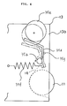
- this example is different from Example 1 in that an adjusting device 35 is provided instead of the fixing unit 15, thereby enabling the mesh plate 14 to kept in contact with the developing roller at an appropriate pressure.
- the adjusting device 35 includes a rotary shaft 35a carried on side walls 13b of the housing 13 along the opening 13a thereof, a connecting rod 35b extended axially with the rotary shaft 35a, and a pin 35c.
- the rotary shaft 35a is chamfered to form a flat surface on which the connecting rod 35b is supported.
- the rotary shaft 35a is fixed to the connecting rod 35b by the pin 35c .
- the connecting rod 35b can be rotated around the pin 35c.
- one end of the rotary shaft 35a is passed through one of the side walls 13b.
- the chamfered surface of the projecting end portion of the rotary shaft 35a supports an end of a rotary lever 35d.
- the rotary lever 35d extends upward and bent in the opposite direction to the photosensitive drum 20.
- This lever 35d touches an eccentric cam 35e mounted on an image forming apparatus (not shown).
- the eccentric cam 35e is intermittently driven by a stepping motor or the like.
- the other end of the rotary lever 35d is connected to a spring 35f which is fixed to the side wall 13b at the other end.
- the spring 35f biases the rotary lever 35d so as to enable it to touch the eccentric cam 35e constantly.
- the rotary lever 35d is stopped at a desired position by a stop pin 35g fixed on the side wall 13b.
- the eccentric cam 35e is rotated, the rotary lever 35d is rotated against the spring 35f so that the mesh plate 14 can be kept in contact with the developing roller at an appropriate pressure.
- the eccentric cam 35e is rotated by the stepping motor.
- the stepping motor is connected to an image density adjusting switch disposed on a control panel so that the stepping motor is rotated a given number of times.
- the mesh plate 14 is excessively pressed upon the developing roller 11, the formation of a thin toner layer results on the developing roller 11. As a result, the latent image on the photosensitive drum 20 is developed with low density because of the shortage of toner. If the mesh plate 14 is lightly pressed upon the developing roller 11, the formation of a thick toner layer results on the developing roller 11, and the latent image on the photosensitive drum 20 is developed with high density because of the extra amount of toner.
- the eccentric cam 35e is rotated until no tension is imparted to the mesh plate 14, thereby releasing the developing roller 11 from the photosensitive drum 20.
- no tension is imparted to the mesh plate 14.
- the mesh is made of a plastic such as nylon which is permanently elongated.
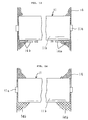
- the mesh plate 14 is longer than the axial length W1 on the urethane rubber surface where toner is coated but shorter than the length of the developing roller 11.
- the end portions of the developing roller 11 are covered with protective strips 14a.
- the strip 14a can be made by bending a plate with the mesh sandwiched or made of a sash to which the mesh is secured.
- the protective strips 14a are stuck to the mesh plate 14 with a heat-proof adhesive such as epoxy adhesive.
- the other structure is the same as Example 1.
- each edge of the mesh plate 14 is covered by the protective strip 14a, the urethane rubber 11b is protected from being scratched by the edges of the mesh plate 14. Otherwise, a scratched urethane rubber is likely to cause the toner to scatter from the broken surface.
- a flash due to scratching is likely to damage the surface of the photosensitive drum 20 and peel the photosensitive layer on the drum 20.
- the life of the photosensitive drum 20 is prolonged. If the developing roller is damaged on the surface, frictional dust will be dispersed, and admixed with the toner. Such mixture is harmful to the formation of an image.
- the mesh plate 14 can withstand a long period of use.
- each mesh holder 50 includes an upper member 51 and a lower member 52 between which the edges of the mesh plate 14 is sandwiched.
- the upper member 51 includes a ridge 51a and the lower member 52 includes a groove 52a so that the ridge 51a fits in the groove 52a to effect the joint between the upper member 51 and the lower member 52.
- a mesh portion of the mesh plate 14 is forced into the groove 52a by the ridge 51a, thereby ensuring that the mesh plate 14 is secured between the upper member 51 and the lower member 52 which are joined by means of screws 53.
- the upper member 51 and the lower member 52 are respectively provided with apertures 51b and 52b at central portions thereof which correspond to each other.
- One of the mesh holders 50 is fixed to the bottom of the housing 13 by means of a bolt 55 passed through the apertures 51b and 52b .
- the mesh holder 50 is fixed to the rotary shaft 15a ( Figure 1) disposed on the opposite side to the bottom of the housing 13 across the opening 13a by means of the bolt 55 passed through the apertures 51b and 52b.
- the mesh plate 14 is under tension imparted by spring boards 59 toward the developing roller 11.
- the spring boards 59 are made in a strip of flexible, tough metal, such as stainless steel and phosphor bronze. As shown in Figure 11, the spring boards 59 are fixed to the mesh plate 14 through joints 56; more specifically, the joint 56 includes a pocket 56a in which a narrowed portion 59a of the spring board 59 is inserted as indicated by the arrow in Figure 11. Since the spring boards 59 are longer than the axial length of the mesh plate 14, they tend to warp when they are fixed to the edges of the mesh plate 14, thereby imparting tension to the mesh plate 14. As a result, the mesh plate 14 is stretched without crease or slack.
- the other structure of this example is the same as Example 1.
- the mesh plate 14 is kept in contact with the developing roller 11 under pressure, wherein the pressure is adjusted by the rotary shaft 15a so as to produce an optimum pressure for the developing roller 11.
- the absence of crease or slack enable the mesh plate to keep contact with the developing roller 11 at an even pressure.
- this example is characteristic in that the mesh plate 14 is provided with a plurality of toner collecting windows 14b aligned under the developing roller 11.
- Each collecting window 14b has an opening of such a size as to allow the toner to pass through.
- the collecting windows 14b preferably have openings of 0.2 to 2 mm by taking into consideration a possible aggregation.
- the shape of the collecting windows 14b can be rectangular, circular, oval or square.
- Figure 14 shows another form of toner collecting means which are provided by a mesh portion below the developing roller 11 having larger openings that those of the part above the developing roller 11.
- an electrode 41 is provided as a further form of toner collecting means.
- a potential of positive polarity (the opposite polarity of the toner) is applied to the electrode 41.
- a vibrator 42 is provided to impart vibration the mesh plate 14.
- the other structure is the same as the embodiment shown in Figure 15.
- a piezoelectric element can be used as the vibrator 42 which generates supersonic wave oscillation in response to a voltage applied thereto.
- the vibration of the motor can be used by transmitting the vibration to the mesh plate 14 by use of a cam link.
- the embodiments having the collecting windows 14b, the electrode 41, and the vibrator 42 have been illustrated. They can be used independently or jointly with the combination of two or more.
Landscapes
- Physics & Mathematics (AREA)
- General Physics & Mathematics (AREA)
- Dry Development In Electrophotography (AREA)
Applications Claiming Priority (2)
| Application Number | Priority Date | Filing Date | Title |
|---|---|---|---|
| JP206451/90 | 1990-08-02 | ||
| JP2206451A JP2625244B2 (ja) | 1990-08-02 | 1990-08-02 | 現像装置 |
Publications (2)
| Publication Number | Publication Date |
|---|---|
| EP0469902A2 true EP0469902A2 (de) | 1992-02-05 |
| EP0469902A3 EP0469902A3 (en) | 1993-03-10 |
Family
ID=16523594
Family Applications (1)
| Application Number | Title | Priority Date | Filing Date |
|---|---|---|---|
| EP19910307063 Ceased EP0469902A3 (en) | 1990-08-02 | 1991-08-01 | A developing device |
Country Status (3)
| Country | Link |
|---|---|
| US (1) | US5166472A (de) |
| EP (1) | EP0469902A3 (de) |
| JP (1) | JP2625244B2 (de) |
Cited By (2)
| Publication number | Priority date | Publication date | Assignee | Title |
|---|---|---|---|---|
| EP0557925A1 (de) * | 1992-02-24 | 1993-09-01 | Kabushiki Kaisha Toshiba | Entwicklungsvorrichtung und damit ausgerüstetes Bilderzeugungsgerät |
| US20220168774A1 (en) * | 2020-11-27 | 2022-06-02 | Seiko Epson Corporation | Powder supply device |
Families Citing this family (16)
| Publication number | Priority date | Publication date | Assignee | Title |
|---|---|---|---|---|
| JPH05165317A (ja) * | 1991-12-13 | 1993-07-02 | Toshiba Corp | 現像装置 |
| US5585895A (en) * | 1991-12-19 | 1996-12-17 | Canon Kabushiki Kaisha | Developing device and process cartridge with it |
| JPH06175485A (ja) * | 1992-12-04 | 1994-06-24 | Konica Corp | 現像装置 |
| US5467175A (en) * | 1992-12-30 | 1995-11-14 | Ricoh Company, Ltd. | Developing device for an image forming apparatus |
| US5384627A (en) * | 1994-03-21 | 1995-01-24 | Xerox Corporation | Developing unit having ceramic donor roll |
| JP3444017B2 (ja) * | 1994-05-18 | 2003-09-08 | 富士ゼロックス株式会社 | 一成分現像剤を用いる現像装置 |
| JPH0962074A (ja) * | 1995-08-23 | 1997-03-07 | Fujitsu Ltd | 電子写真画像形成装置 |
| KR0174689B1 (ko) * | 1996-09-11 | 1999-04-01 | 삼성전자주식회사 | 현상롤러의 고스트 방지장치 |
| US6631250B2 (en) * | 2001-12-07 | 2003-10-07 | Xerox Corporation | Developer filtration module |
| US7888709B2 (en) * | 2004-09-15 | 2011-02-15 | Sonetics Ultrasound, Inc. | Capacitive micromachined ultrasonic transducer and manufacturing method |
| JP5177191B2 (ja) * | 2010-09-06 | 2013-04-03 | ブラザー工業株式会社 | 現像装置 |
| JP5760437B2 (ja) * | 2010-12-28 | 2015-08-12 | ブラザー工業株式会社 | 現像装置 |
| US20120189370A1 (en) * | 2011-01-25 | 2012-07-26 | Xerox Corporation | Media protector for image-forming device |
| JP5917439B2 (ja) * | 2013-05-24 | 2016-05-11 | 株式会社沖データ | 現像装置及び画像形成装置 |
| JP6186925B2 (ja) * | 2013-06-19 | 2017-08-30 | 株式会社リコー | 現像装置および画像形成装置 |
| JP7484657B2 (ja) * | 2020-10-23 | 2024-05-16 | セイコーエプソン株式会社 | 粉体供給装置 |
Family Cites Families (9)
| Publication number | Priority date | Publication date | Assignee | Title |
|---|---|---|---|---|
| JPS56123554A (en) * | 1980-03-04 | 1981-09-28 | Canon Inc | Developing method and apparatus |
| DE3107055A1 (de) * | 1980-03-04 | 1982-01-07 | Canon K.K., Tokyo | "entwicklungsvorrichtung" |
| JPS58118678A (ja) * | 1982-01-09 | 1983-07-14 | Canon Inc | 現像装置 |
| US4556013A (en) * | 1983-11-07 | 1985-12-03 | Xerox Corporation | Screened donor for touchdown development |
| JPS60103374A (ja) * | 1983-11-11 | 1985-06-07 | Fuji Xerox Co Ltd | 電子複写機の現像装置 |
| JPS61179473A (ja) * | 1985-02-04 | 1986-08-12 | Canon Inc | 現像装置 |
| JPS63273888A (ja) * | 1987-05-01 | 1988-11-10 | Ricoh Co Ltd | 静電記録装置の現像装置 |
| US4986807A (en) * | 1989-01-23 | 1991-01-22 | Interventional Technologies, Inc. | Atherectomy cutter with radially projecting blade |
| JPH02206456A (ja) * | 1989-02-03 | 1990-08-16 | Morita Mfg Co Ltd | 歯科診療用インスツルメントの収納装置 |
-
1990
- 1990-08-02 JP JP2206451A patent/JP2625244B2/ja not_active Expired - Lifetime
-
1991
- 1991-08-01 US US07/739,158 patent/US5166472A/en not_active Expired - Fee Related
- 1991-08-01 EP EP19910307063 patent/EP0469902A3/en not_active Ceased
Cited By (3)
| Publication number | Priority date | Publication date | Assignee | Title |
|---|---|---|---|---|
| EP0557925A1 (de) * | 1992-02-24 | 1993-09-01 | Kabushiki Kaisha Toshiba | Entwicklungsvorrichtung und damit ausgerüstetes Bilderzeugungsgerät |
| US20220168774A1 (en) * | 2020-11-27 | 2022-06-02 | Seiko Epson Corporation | Powder supply device |
| US11638929B2 (en) * | 2020-11-27 | 2023-05-02 | Seiko Epson Corporation | Powder supply device |
Also Published As
| Publication number | Publication date |
|---|---|
| US5166472A (en) | 1992-11-24 |
| JPH0490568A (ja) | 1992-03-24 |
| JP2625244B2 (ja) | 1997-07-02 |
| EP0469902A3 (en) | 1993-03-10 |
Similar Documents
| Publication | Publication Date | Title |
|---|---|---|
| US5166472A (en) | Developing device having a porous plate | |
| US4791882A (en) | Loosely mounted outer sleeve member with biasing means | |
| US4478505A (en) | Developing apparatus for improved charging of flying toner | |
| JPH0553444A (ja) | 電子写真式印刷システム | |
| US5389733A (en) | Developing device for an image forming apparatus | |
| US4994859A (en) | Power cloud developing apparatus with a first and second electric field curtain generating means | |
| EP0572738B1 (de) | Aufladungsvorrichtung, Bilderzeugungsgerät und von dem Bilderzeugungsgerät abnehmbare Arbeitseinheit | |
| US5233395A (en) | Image forming apparatus having a transfer brush of electroconductive fibers | |
| US5737676A (en) | Latent electrostatic image developing device having regulating blade with chamfer | |
| US6070043A (en) | Device for cleaning a transfer belt of an image-forming machine | |
| EP0691587A1 (de) | Vorrichtung zur Entwicklung von elektrostatischen latenten Bildern | |
| JPH09138557A (ja) | 静電潜像現像装置 | |
| US6289197B1 (en) | Developer feeding member wherein its free end has a smaller elastic flexural characteristic relative to its supporting end and developing device having the same | |
| US5729803A (en) | Device for developing electrostatic latent image which prevents solidification of developing agent by vibration | |
| EP0856779A2 (de) | Vorrichtung zur Entwicklung von elektrostatischen, latenten Bildern | |
| US5177533A (en) | Image forming apparatus | |
| JP2996448B2 (ja) | 画像形成装置 | |
| JP3212797B2 (ja) | 電子写真装置の現像装置 | |
| JP2006171468A (ja) | 現像装置、プロセスカートリッジ及び画像形成装置 | |
| JP2573433B2 (ja) | 画像形成装置 | |
| JPH0588532A (ja) | 画像形成装置 | |
| JPH10232544A (ja) | 現像装置 | |
| JPH09106179A (ja) | 現像装置、プロセスカートリッジ及び画像形成装置 | |
| JP3082276B2 (ja) | 画像形成装置 | |
| JPH04323676A (ja) | 画像形成装置 |
Legal Events
| Date | Code | Title | Description |
|---|---|---|---|
| PUAI | Public reference made under article 153(3) epc to a published international application that has entered the european phase |
Free format text: ORIGINAL CODE: 0009012 |
|
| AK | Designated contracting states |
Kind code of ref document: A2 Designated state(s): DE FR GB IT |
|
| PUAL | Search report despatched |
Free format text: ORIGINAL CODE: 0009013 |
|
| AK | Designated contracting states |
Kind code of ref document: A3 Designated state(s): DE FR GB IT |
|
| 17P | Request for examination filed |
Effective date: 19930430 |
|
| 17Q | First examination report despatched |
Effective date: 19941011 |
|
| GRAG | Despatch of communication of intention to grant |
Free format text: ORIGINAL CODE: EPIDOS AGRA |
|
| STAA | Information on the status of an ep patent application or granted ep patent |
Free format text: STATUS: THE APPLICATION HAS BEEN REFUSED |
|
| 18R | Application refused |
Effective date: 19960614 |