EP0469907A2 - Periodisch wirkender Flüssigkeitsstrahlerzeuger - Google Patents
Periodisch wirkender Flüssigkeitsstrahlerzeuger Download PDFInfo
- Publication number
- EP0469907A2 EP0469907A2 EP91307079A EP91307079A EP0469907A2 EP 0469907 A2 EP0469907 A2 EP 0469907A2 EP 91307079 A EP91307079 A EP 91307079A EP 91307079 A EP91307079 A EP 91307079A EP 0469907 A2 EP0469907 A2 EP 0469907A2
- Authority
- EP
- European Patent Office
- Prior art keywords
- piston
- fluid
- valve
- main
- piston means
- Prior art date
- Legal status (The legal status is an assumption and is not a legal conclusion. Google has not performed a legal analysis and makes no representation as to the accuracy of the status listed.)
- Withdrawn
Links
- 239000007788 liquid Substances 0.000 title description 2
- 239000012530 fluid Substances 0.000 claims abstract description 156
- 230000000740 bleeding effect Effects 0.000 claims abstract description 14
- 238000004891 communication Methods 0.000 claims abstract description 9
- 230000000903 blocking effect Effects 0.000 claims abstract description 7
- 230000004044 response Effects 0.000 claims abstract description 5
- 230000009471 action Effects 0.000 claims description 4
- 238000011144 upstream manufacturing Methods 0.000 claims description 3
- 230000015572 biosynthetic process Effects 0.000 claims description 2
- 230000006835 compression Effects 0.000 claims description 2
- 238000007906 compression Methods 0.000 claims description 2
- 230000008439 repair process Effects 0.000 claims description 2
- 238000004140 cleaning Methods 0.000 description 4
- 230000006870 function Effects 0.000 description 2
- 238000000034 method Methods 0.000 description 2
- 238000007789 sealing Methods 0.000 description 2
- 230000003292 diminished effect Effects 0.000 description 1
- 238000007599 discharging Methods 0.000 description 1
- 230000000694 effects Effects 0.000 description 1
- 230000008030 elimination Effects 0.000 description 1
- 238000003379 elimination reaction Methods 0.000 description 1
- 238000005516 engineering process Methods 0.000 description 1
- 230000007257 malfunction Effects 0.000 description 1
- 239000000463 material Substances 0.000 description 1
- 230000007246 mechanism Effects 0.000 description 1
- 230000004048 modification Effects 0.000 description 1
- 238000012986 modification Methods 0.000 description 1
- 230000037361 pathway Effects 0.000 description 1
- 230000008569 process Effects 0.000 description 1
- 230000009467 reduction Effects 0.000 description 1
- 230000003252 repetitive effect Effects 0.000 description 1
- 239000007787 solid Substances 0.000 description 1
- XLYOFNOQVPJJNP-UHFFFAOYSA-N water Substances O XLYOFNOQVPJJNP-UHFFFAOYSA-N 0.000 description 1
Images

Classifications
-
- B—PERFORMING OPERATIONS; TRANSPORTING
- B05—SPRAYING OR ATOMISING IN GENERAL; APPLYING FLUENT MATERIALS TO SURFACES, IN GENERAL
- B05B—SPRAYING APPARATUS; ATOMISING APPARATUS; NOZZLES
- B05B12/00—Arrangements for controlling delivery; Arrangements for controlling the spray area
- B05B12/02—Arrangements for controlling delivery; Arrangements for controlling the spray area for controlling time, or sequence, of delivery
- B05B12/06—Arrangements for controlling delivery; Arrangements for controlling the spray area for controlling time, or sequence, of delivery for effecting pulsating flow
-
- Y—GENERAL TAGGING OF NEW TECHNOLOGICAL DEVELOPMENTS; GENERAL TAGGING OF CROSS-SECTIONAL TECHNOLOGIES SPANNING OVER SEVERAL SECTIONS OF THE IPC; TECHNICAL SUBJECTS COVERED BY FORMER USPC CROSS-REFERENCE ART COLLECTIONS [XRACs] AND DIGESTS
- Y10—TECHNICAL SUBJECTS COVERED BY FORMER USPC
- Y10T—TECHNICAL SUBJECTS COVERED BY FORMER US CLASSIFICATION
- Y10T137/00—Fluid handling
- Y10T137/8593—Systems
- Y10T137/86389—Programmer or timer
-
- Y—GENERAL TAGGING OF NEW TECHNOLOGICAL DEVELOPMENTS; GENERAL TAGGING OF CROSS-SECTIONAL TECHNOLOGIES SPANNING OVER SEVERAL SECTIONS OF THE IPC; TECHNICAL SUBJECTS COVERED BY FORMER USPC CROSS-REFERENCE ART COLLECTIONS [XRACs] AND DIGESTS
- Y10—TECHNICAL SUBJECTS COVERED BY FORMER USPC
- Y10T—TECHNICAL SUBJECTS COVERED BY FORMER US CLASSIFICATION
- Y10T137/00—Fluid handling
- Y10T137/8593—Systems
- Y10T137/87265—Dividing into parallel flow paths with recombining
Definitions
- This invention relates to fluid operated conduit cleaning systems and, more particularly, to a valve unit for producing high volume, high pressure, pulsed delivery of a fluid, as for introduction into a conduit for purposes of cleaning the inside passage thereof.
- Opening of blocked and silted drainage, sewer and other conduits is a vexatious problem that has plagued the industry for many years. It is not uncommon for conduits to run uninterrupted for hundreds of feet without any access structure for cleanout. To further aggravate the problem, these conduits may have one or more sharp bends, which makes conventional rodding techniques inadequate. A still further problem is that frequently the obstructing material will be positively adhered to the inside conduit surface.
- the use of a flexible rod may do nothing more than bore a restricted opening through the obstruction which thereby allows only a limited flow volume.
- Burns ′518 patent To overcome the last mentioned problem, it is known to provide an additional nozzle passageway to generate a forwardly facing, high pressure fluid jet, as shown in the above-noted Burns ′518 patent, to blast through the obstruction. It is possible with conventional technology to employ this type of system to penetrate blocked and heavily silted lines up to as much as 400 feet in length. These systems are generally adequate for most industrial, municipal, and household applications through manhole access. However, this system may not be adequate where curves, elbows, and traps are encountered and/or when the conduit length significantly exceeds 400 feet.
- Flaherty employs two pistons which alternatingly operate to discharge fluid through an outlet. Pulses from the separate pistons are timed to immediately follow one another. It is also possible to disable one of the pistons to provide a lag between successive pulses by a single one of the pistons.
- the Flaherty system is relatively complicated. For example, there are five check valves on the system and multiple moving pistons. Failure of any element may result in system malfunction. Another problem with the Flaherty system is that it is inherently quite cumbersome by reason of there being multiple pistons and flow passageways associated therewith. It is a desirable objective of planners of such systems to minimize their size, due to the fact that most such systems are regularly transported and used in the field.
- Kellan also employs a reciprocating closure which alternatingly seats and unseats to produce pulsed delivery of an incoming supply of fluid to a point of use.
- One drawback with Kellan is that once the closure is seated no additional water flows from the inlet towards the outlet. The result of this is the development of an air pocket immediately downstream of the closure. Upon the closure unseating, the volume and pressure of the pulse is reduced over what it would be in the absence of the air pocket. Pressure loss results in a less effective conduit cleaning and advancing action for a nozzle.
- the present invention is specifically directed to overcoming the above enumerated problems in a novel and simple manner.
- a valve unit for producing pulsed delivery of a fluid from a supply to a point of use.
- the valve unit consists of: a valve housing defining a main fluid chamber and inlet and outlet openings communicating with the main fluid chamber; a piston movable between first and second positions within the main fluid chamber for blocking incoming fluid flow from the inlet opening through the main fluid chamber to the outlet opening with the piston in its first position and for allowing free communication of incoming fluid flow from the inlet opening through the main fluid chamber to the outlet opening with the piston means in its second position; structure for repetitively moving the piston back and forth between its first and second positions in response to a fluid being supplied under pressure at the inlet opening, there being a charge of fluid discharged through the outlet opening in the time interval in which the piston moves out of its first position, into its second position, and back to its first position; and bleeding structure for communicating fluid from the inlet opening to a location downstream of the piston with the piston in its first position.
- the above structure maximizes the pressure and volume of each fluid pulse/charge.
- the bleeding structure prevents the formation of air pockets downstream of the piston. As a result, at the instant the piston opens, the incoming fluid flow encounters a substantially solid wall of fluid. In the absence of the bleeding feature, the incoming fluid would flow into an air pocket so that the resulting pulse of fluid that would be discharged before the piston moves back to its first position would be diminished.
- the present invention also contemplates a positive acting valve unit that has a minimal number of moving parts.
- the piston is biased towards its first position.
- the piston has a valve disc that nests against a first valve seat in the main fluid chamber and blocks incoming fluid flow from the inlet opening through the main fluid chamber to the outlet opening with the piston in its first position.
- the piston has a main piston body movably mounted within the main fluid chamber and a valve disc mounted movably relative to the main piston body between a third position, wherein the valve disc abuts a second seat on the main piston body so that the valve disc follows movement of the main piston body as the piston moves from its second position towards its first position, and a fourth position wherein the valve disc is spaced from the second seat on the main piston body.
- the valve disc is normally biased into its third position and has a first pressure face and a seating face for nesting against the first valve seat.
- the main piston body has separate second and third pressure faces.
- the piston main body, valve disc, and structure for movably mounting the valve disc and for movably biasing the valve disc make up a part of the piston moving structure.
- the piston moving structure is operable by incoming fluid flowing through the inlet opening with the piston in its first position.
- the incoming fluid acts on the first and second pressure faces to urge the valve disc seating face against the valve seat and, at a first predetermined incoming pressure, causes the second valve seat on the main piston body to move away from the valve disc against the valve disc biasing structure.
- the biasing structure for the valve disc includes structure for developing a progressively increasing force on the valve disc tending to bias the valve disc into its third position as the valve disc and second valve seat on the main piston body are moved away from each other.
- the structure for developing the progressively increasing force on the valve disc causes the valve disc to unseat from the first valve seat upon the second valve seat on the main piston body moving a predetermined distance away from the valve disc whereupon fluid from the inlet opening can flow freely through the main chamber to the fluid outlet.
- a bypass structure is provided for communicating fluid with the main fluid chamber at first and second locations, respectively downstream and upstream of the piston.
- a portion of the incoming fluid flowing toward the outlet opening enters the bypass at the first location and flows through the bypass structure and out at the second location to impinge on the third pressure face until the pressure on the piston, urging the piston towards its second position, equalizes with the fluid pressure on the third pressure face urging the piston towards its first position, whereupon the biasing structure for the piston urges the piston back to its first position.
- a one-way valve is provided for blocking backflow of fluid from the main flow chamber at the second location through the bypass chamber to the main flow chamber at the first location.
- the bleeding structure comprises a passageway for communicating incoming fluid through the valve disc toward the outlet opening with the piston in its first position.
- the present invention also contemplates structure for varying the length, maximum pressure, and volume of each fluid pulse. This is accomplished by varying the bias force exerted by the biasing structure on the piston, which force tends to urge the piston towards its first position.
- This adjusting structure is preferably in the form of a second piston which is movably mounted relative to the housing to control the compression of a coil spring acting between the first and second pistons. Movement of the piston is preferably accomplished by a rod threaded through the housing and having an external control head through which the rod and associated second piston can be repositioned.
- the force of the coil spring on the second piston can be reduced to the point that the first piston cannot realize its first position. This allows the elimination of the crisp division between the pulses and allows the valve to be adjusted to a no-pulse, relatively constant flow condition.
- the first piston is preferably provided with a blind bore to accommodate the coil spring.
- the present invention also contemplates a valve unit for producing pulsed delivery of a liquid and consisting of: a valve housing defining a main fluid chamber and inlet and outlet openings communicating with the main fluid chamber; a piston with first and second opposite ends movable between first and second positions within the main fluid chamber for blocking incoming fluid from the inlet opening through the main fluid chamber to the outlet opening with the piston in its first position and for allowing free communication of incoming fluid flow from the inlet opening through the main fluid chamber to the outlet opening with the piston in its second position, there being a charge of fluid that is discharged through the outlet opening in the time interval in which the piston moves out of its first position into its second position and back to its first position; and structure for repetitively moving the piston back and forth between its first and second positions in response to a fluid being supplied under pressure at the inlet opening and including bypass structure for communicating with the main chamber at first and second locations at the first and second opposite piston ends.
- the fluid pressure on the second piston end exerts a force tending to move the piston towards its first position and the
- a generic housing is designed to accept a removable end cap.
- the end cap can be provided with part of the bias adjusting structure on the piston.
- a cap without any adjusting structure can be employed which fixes the operating characteristics for the valve unit.
- Fig. 1 is a schematic representation of a conduit cleaning system at 10 in association with a length of conduit 12.
- the system 10 incorporates an in line valve unit 13, according to the present invention, for producing pulsed delivery of fluid from a pressurized supply 16 through a flexible supply hose 18 to a nozzle 20.
- the nozzle 20 is directed through the open end 22 of the conduit 12 and advanced lengthwise therewithin in operation.
- the nozzle 20 has a lengthwise bore 26 with a fluid outlet 28 at the rounded, leading end 30 thereof.
- the nozzle 20 has spaced passageways 32, 34 for directing separate jets of fluid 36, 38, respectively, angularly rearwardly from the nozzle 20 to impinge on the inside surface 40 of the conduit 12. While two jets 36, 38 of fluid are shown, any number of fluid jets 32, 34 can be developed in circumferentially spaced relationship about the nozzle 20.
- the fluid impinging on the inside conduit surface 40 at the angle shown in Fig. 1, causes the nozzle 20 to advance in the direction of arrow 42 in Fig. 1.
- the fluid jet 44 emanating from the leading end 30 of the nozzle 20 impacts obstructions in front of the nozzle 20 to effect breakup thereof and define an opening therethrough into which the nozzle 20 can pass.
- the jets 36, 38 at the same time scour the inside conduit surface 40 as the nozzle 20 advances within the conduit 12. By drawing rearwardly on the hose 18, the jets 36, 38 are caused to effectively "scrape" the inside surface 40 of the conduit 12.
- the present invention is directed to the structure 13 for causing the pulsed delivery of fluids from the supply 16 to the hose 18 and nozzle 20.
- one extremely desirable feature of the present invention is that it is very compact, with a minimal number of moving parts. It can be simply spliced into an existing high pressure line to produce the pulsed output of fluid.
- the valve 13 consists of a housing 46 having a square, round, or other suitable cross-sectional configuration.
- the housing 46 has a stepped through bore 48 with a small diameter bore section 50 and a large diameter, concentric bore section 52.
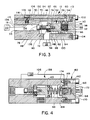
- the bore sections 50, 52 together define a main fluid chamber 54 having an inlet opening 56 and outlet opening 55 in communication therewith. Fluid from the supply 16 flows through the inlet opening 56 into and through the chamber 54, through the outlet opening 55 to the hose 18 and ultimately to the nozzle 20.
- the piston means 58 consists of a main piston body 60 with a stepped configuration including a cylindrical first section 62 and an enlarged second section 64.
- the first piston body section 62 has a blind, threaded bore 66 therein which accepts the threaded end 68 of a shoulder bolt 70.
- the bolt 70 has a body 72 of substantially uniform diameter with the diameter thereof being larger than the diameter of the threaded bolt end 68. At the juncture of the threaded end 68 and body 72, an annular shoulder is defined for abutment with the free end 76 of the piston body 60.
- the bolt 70 has an enlarged head 78 defining an axially facing, annular shoulder 80.
- the bolt 70 supports a valve disc 82 which closely surrounds and is slidable guidingly lengthwise over the bolt body 72. With the bolt 70 assembled to the piston body 60, the valve disc 82 is captively maintained between the free end 76 of the piston body 60 and the shoulder 80 on the enlarged head 78 on the bolt 70.
- a coil spring 84 surrounds the bolt body 72 and acts between the valve disc 82 and shoulder 80 to bias the valve disc 82 into a third position against the free end 76 of the piston body 60.
- the open end 86 of the housing 46 is sealed by an end cap 88 having an annular extension 90 with an axially opening blind bore 92 therein.
- the piston body 60 has a blind bore 94 that is coaxial with the bore 92 in the end cap 88.
- a coil spring 96 is interposed between the wall surfaces 98, 100, respectively at the bottom of the bores 92, 94. The coil spring 96 normally biases the piston means 58 into the Fig. 2 position.
- the end cap 88 is removably held securely in place on the housing 46 as by bolts 102, 104.
- a bypass chamber 106 is provided in the housing 46 and communicates with the main fluid chamber 54 between a first location 108 downstream of the piston means 58 and a second location 110 upstream of the piston means 58.
- a three-step bore 112 communicates between the bypass chamber 106 and the main chamber 54 at the first location 108.
- First and second bore sections 114, 116, respectively, define an annular seat 118 for a plunger 120 on a one-way valve 122 that is normally urged by a coil spring 124 into the closed position shown in Figs. 2 and 3.
- the valve plunger 120 has a control orifice 123 therethrough to maintain communication between the first and second locations 108, 110 in the main fluid chamber 54.
- the diameter of the orifice 123 dictates the pulse rate, as will be evident from the description below.
- a plug 126 is threaded into the housing 46 to permit assembly and/or repair of the one-way valve 122.
- valve unit 13 The operation of the valve unit 13 is as follows. Fluid from the supply 16 is introduced through the inlet opening 56 with the piston means 58 in the first position of Fig. 2. With the piston means in its first position, a seating face 128 on the valve disc 82 bears sealingly against an annular seat 130 defined by the stepped through bore 48. Upon the pressurized fluid being introduced from the supply 16, it impinges upon a first pressure surface 132 on the valve disc 82 and an oppositely facing, second pressure surface 134 on the piston body 60. As the pressure builds at the inlet opening 56, the fluid urges the piston body 60 to the right in Fig. 2 while at the same time maintaining the valve disc 82 in its seated, Fig. 2 position.
- the pressure buildup from the piston body 60 causes a discharge of fluid through the orifice 123 at the first location 108. Movement of the piston body 60 compresses spring 96 so as to increase the restoring force therein, and also compresses the coil spring 84 between the valve disc 82 and enlarged head 78 on the bolt 70. Upon a predetermined movement of the piston body 60 away from the seated valve disk 82, the coil spring 84 causes the valve disc 82 to unseat, as shown in Fig. 3, which thereby allows free flow of fluid through the opening 136, previously blocked by the valve disc 82, and through the outlet opening 55. Upon the valve disc 82 unseating, the seating face 138 of the valve disc 82 is exposed so that the incoming fluid forces the valve disc 82 back against the free end/seat 76 of the piston body 60, to its third position shown in Fig. 3.
- the bleeding means consists of a non-axial passageway which allows fluid flow from the inlet opening 56 through the valve disc 82 and into the bore section 50 with the piston means 58 in the closed position of Fig. 2.
- the significance of this is that the bore section 50 and hose 18 remains substantially filled with fluid, even with the piston means 58 in the closed position of Fig. 2.
- the incoming fluid from the supply 16 is caused to produce a pulse of fluid through the outlet opening 55 and nozzle 20. This maximizes the flow volume and pressure for each pulse.
- a sealing O-ring 148 is provided in an undercut 150 to seal between the outer surface 152 of the section 64 and the guiding surface 154 therefor on the housing 46.
- a seal 156 is also provided between the end cap 88 and the housing 46 to prevent leakage.
- the principal distinction between the valve 158 and valve 13 shown in Figs. 2 and 3 is a modification to the end cap at 160 which allows for variation in the force of the spring 96.
- the end cap 160 has a stepped through bore 162 with a second piston 164, with a sealing O-ring 165 thereon, movable guidingly axially along the bore 162.
- the bore 162 has an associated rod 166 threaded in a bore 168 through the cap body 170.
- An exposed control head 172 is attached to the rod 166 to facilitate its rotation.
- the coil spring 96 is interposed between the piston body 60 and an axially facing surface 174 of the second piston 164.
- the piston By turning the rod 166 through the control head 172, the piston is caused to be moved selectively in opposite axial directions. Movement of the rod 166 to the left in Fig. 4 increases the compressive force on the spring 96 to thereby shorten the fluid discharge interval and resulting pulse, whereas opposite movement of the rod 166 lengthens the fluid discharge pulse.
- the end caps 88, 160 are interchangeable and can be selectively placed on the housing 46 by the user depending upon whether the adjusting capability is desired or not.
Landscapes
- Nozzles (AREA)
Applications Claiming Priority (2)
| Application Number | Priority Date | Filing Date | Title |
|---|---|---|---|
| US07/561,946 US5070907A (en) | 1990-08-02 | 1990-08-02 | Pulsating liquid jet apparatus |
| US561946 | 1990-08-02 |
Publications (2)
| Publication Number | Publication Date |
|---|---|
| EP0469907A2 true EP0469907A2 (de) | 1992-02-05 |
| EP0469907A3 EP0469907A3 (en) | 1992-05-06 |
Family
ID=24244158
Family Applications (1)
| Application Number | Title | Priority Date | Filing Date |
|---|---|---|---|
| EP19910307079 Withdrawn EP0469907A3 (en) | 1990-08-02 | 1991-08-01 | Pulsating liquid jet apparatus |
Country Status (3)
| Country | Link |
|---|---|
| US (1) | US5070907A (de) |
| EP (1) | EP0469907A3 (de) |
| CA (1) | CA2047291A1 (de) |
Families Citing this family (3)
| Publication number | Priority date | Publication date | Assignee | Title |
|---|---|---|---|---|
| US5364240A (en) * | 1993-10-14 | 1994-11-15 | Spartan Tool Div. Of Pettibone Corp. | Fluid pump with pulsing feature |
| US6220529B1 (en) | 2000-02-10 | 2001-04-24 | Jet Edge Division Tc/American Monorail, Inc. | Dual pressure valve arrangement for waterjet cutting system |
| US9533856B2 (en) | 2014-05-19 | 2017-01-03 | Spartan Tool L.L.C. | System for measuring payout length of an elongate member |
Family Cites Families (18)
| Publication number | Priority date | Publication date | Assignee | Title |
|---|---|---|---|---|
| US1218567A (en) * | 1914-01-05 | 1917-03-06 | Edward L Kellan | Automatic valve device for distributing liquid under pressure. |
| US1176518A (en) * | 1915-10-19 | 1916-03-21 | John Thomas Burns | Self-propelling hose-nozzle. |
| US1796941A (en) * | 1928-05-31 | 1931-03-17 | Jr Francis M Pottenger | Sprinkler system |
| US2069340A (en) * | 1934-05-28 | 1937-02-02 | William S White | Automatic intermittent flush valve |
| US2620825A (en) * | 1943-09-25 | 1952-12-09 | Joseph G Cannon | Automatic cycling valve |
| US2580433A (en) * | 1944-11-30 | 1952-01-01 | Kain Clifford Hasty | Valve |
| US3230839A (en) * | 1962-04-30 | 1966-01-25 | Gaston Raoul Hugh De | Air power wrenches |
| US3216328A (en) * | 1963-10-24 | 1965-11-09 | Axel H Peterson | Vibrator or like apparatus operating on elastic fluid |
| US3448765A (en) * | 1965-09-07 | 1969-06-10 | Intercontinental Chem Corp | Automatic pulse valve |
| US3430652A (en) * | 1966-08-04 | 1969-03-04 | Houdaille Industries Inc | Intermittently operable fluid ballast mechanism |
| US3380348A (en) * | 1966-08-15 | 1968-04-30 | Airmatic Valve Inc | Pneumatic reciprocating valve |
| US3494376A (en) * | 1967-10-12 | 1970-02-10 | Honeywell Inc | Control apparatus |
| US4114515A (en) * | 1975-07-30 | 1978-09-19 | Pauliukonis Richard S | Adjustable self-reciprocating operator |
| US4077569A (en) * | 1976-10-04 | 1978-03-07 | Teledyne Industries, Inc. | Fluid-flow pulsator |
| US4265403A (en) * | 1979-05-09 | 1981-05-05 | Advanced Products Development Corporation | Controlled irrigation system for a predetermined area |
| GB2109271B (en) * | 1981-11-25 | 1985-05-22 | Vauldale Engineering Limited | Pulsating liquid jet apparatus |
| IL74332A (en) * | 1985-02-13 | 1991-09-16 | Rosenberg Peretz | Pulsator device for converting line fluid pressure to a pulsating pressure |
| US4838768A (en) * | 1987-10-15 | 1989-06-13 | Flaherty William J | Convertible pump system |
-
1990
- 1990-08-02 US US07/561,946 patent/US5070907A/en not_active Expired - Fee Related
-
1991
- 1991-07-17 CA CA002047291A patent/CA2047291A1/en not_active Abandoned
- 1991-08-01 EP EP19910307079 patent/EP0469907A3/en not_active Withdrawn
Also Published As
| Publication number | Publication date |
|---|---|
| US5070907A (en) | 1991-12-10 |
| EP0469907A3 (en) | 1992-05-06 |
| CA2047291A1 (en) | 1992-02-03 |
Similar Documents
| Publication | Publication Date | Title |
|---|---|---|
| US6412516B1 (en) | Dry shut-off cartridge | |
| US8251773B2 (en) | Control system for a fluid/abrasive jet cutting arrangement | |
| US6698629B2 (en) | Comestible fluid dispensing tap and method | |
| US3831845A (en) | Fluid delivery system | |
| CA2182446A1 (en) | Apparatus and Method for Electronically Controlling Inlet Flow and Preventing Backflow in a Compressor | |
| EP0631054A2 (de) | Umleitungsventil für Hochdruckreiniger | |
| US5070907A (en) | Pulsating liquid jet apparatus | |
| NZ504251A (en) | A filter having a cleaning nozzle with valve which provides pressure drop and control of fluid flow direction | |
| US3414196A (en) | Self-cleaning tip for airless spray guns | |
| EP0058688A1 (de) | Steuervorrichtung eines flüssigkeitsstroms | |
| US5364240A (en) | Fluid pump with pulsing feature | |
| US4949747A (en) | Self-flushing fluid apparatus particularly useful in pulsator devices | |
| US5249645A (en) | Pressure fluid actuated lubricator | |
| US5580225A (en) | Pulsation causing check valve assembly for a plural piston pump system | |
| US8973608B2 (en) | Adjustable fluid pressure amplifier | |
| US7278443B2 (en) | Pulsation causing valve for a plural piston pump | |
| AU720297B2 (en) | A dispensing device | |
| US5163465A (en) | Vacuum breaker venting valve | |
| AU708125B3 (en) | A water pump | |
| US7290561B2 (en) | Pulsation causing valve for a plural piston pump | |
| RU2175877C1 (ru) | Устройство для импульсной подачи и мелкодисперсного распыления жидких и порошкообразных огнетушащих веществ | |
| JP2739020B2 (ja) | 高圧作動バルブ付きノズル | |
| SU1483155A1 (ru) | Запорное устройство | |
| EP1586382A2 (de) | Sperrventil für Sprühpistolen von Reinigungsapparaten | |
| AU8421498A (en) | A valve |
Legal Events
| Date | Code | Title | Description |
|---|---|---|---|
| PUAI | Public reference made under article 153(3) epc to a published international application that has entered the european phase |
Free format text: ORIGINAL CODE: 0009012 |
|
| AK | Designated contracting states |
Kind code of ref document: A2 Designated state(s): DE FR GB NL |
|
| PUAL | Search report despatched |
Free format text: ORIGINAL CODE: 0009013 |
|
| AK | Designated contracting states |
Kind code of ref document: A3 Designated state(s): DE FR GB NL |
|
| 17P | Request for examination filed |
Effective date: 19930105 |
|
| 17Q | First examination report despatched |
Effective date: 19940316 |
|
| STAA | Information on the status of an ep patent application or granted ep patent |
Free format text: STATUS: THE APPLICATION IS DEEMED TO BE WITHDRAWN |
|
| 18D | Application deemed to be withdrawn |
Effective date: 19940727 |