EP0470114B1 - Mecanisme de direction pour vehicules - Google Patents
Mecanisme de direction pour vehicules Download PDFInfo
- Publication number
- EP0470114B1 EP0470114B1 EP90906205A EP90906205A EP0470114B1 EP 0470114 B1 EP0470114 B1 EP 0470114B1 EP 90906205 A EP90906205 A EP 90906205A EP 90906205 A EP90906205 A EP 90906205A EP 0470114 B1 EP0470114 B1 EP 0470114B1
- Authority
- EP
- European Patent Office
- Prior art keywords
- bearing bushes
- steering
- steering gear
- protrusions
- sector
- Prior art date
- Legal status (The legal status is an assumption and is not a legal conclusion. Google has not performed a legal analysis and makes no representation as to the accuracy of the status listed.)
- Expired - Lifetime
Links
- 238000005553 drilling Methods 0.000 abstract 1
- 239000000428 dust Substances 0.000 description 2
- 230000005540 biological transmission Effects 0.000 description 1
- 238000007789 sealing Methods 0.000 description 1
Images

Classifications
-
- F—MECHANICAL ENGINEERING; LIGHTING; HEATING; WEAPONS; BLASTING
- F16—ENGINEERING ELEMENTS AND UNITS; GENERAL MEASURES FOR PRODUCING AND MAINTAINING EFFECTIVE FUNCTIONING OF MACHINES OR INSTALLATIONS; THERMAL INSULATION IN GENERAL
- F16H—GEARING
- F16H57/00—General details of gearing
- F16H57/02—Gearboxes; Mounting gearing therein
- F16H57/021—Shaft support structures, e.g. partition walls, bearing eyes, casing walls or covers with bearings
- F16H57/022—Adjustment of gear shafts or bearings
-
- B—PERFORMING OPERATIONS; TRANSPORTING
- B62—LAND VEHICLES FOR TRAVELLING OTHERWISE THAN ON RAILS
- B62D—MOTOR VEHICLES; TRAILERS
- B62D3/00—Steering gears
- B62D3/02—Steering gears mechanical
- B62D3/04—Steering gears mechanical of worm type
- B62D3/06—Steering gears mechanical of worm type with screw and nut
-
- F—MECHANICAL ENGINEERING; LIGHTING; HEATING; WEAPONS; BLASTING
- F16—ENGINEERING ELEMENTS AND UNITS; GENERAL MEASURES FOR PRODUCING AND MAINTAINING EFFECTIVE FUNCTIONING OF MACHINES OR INSTALLATIONS; THERMAL INSULATION IN GENERAL
- F16C—SHAFTS; FLEXIBLE SHAFTS; ELEMENTS OR CRANKSHAFT MECHANISMS; ROTARY BODIES OTHER THAN GEARING ELEMENTS; BEARINGS
- F16C35/00—Rigid support of bearing units; Housings, e.g. caps, covers
- F16C35/04—Rigid support of bearing units; Housings, e.g. caps, covers in the case of ball or roller bearings
- F16C35/06—Mounting or dismounting of ball or roller bearings; Fixing them onto shaft or in housing
- F16C35/067—Fixing them in a housing
-
- F—MECHANICAL ENGINEERING; LIGHTING; HEATING; WEAPONS; BLASTING
- F16—ENGINEERING ELEMENTS AND UNITS; GENERAL MEASURES FOR PRODUCING AND MAINTAINING EFFECTIVE FUNCTIONING OF MACHINES OR INSTALLATIONS; THERMAL INSULATION IN GENERAL
- F16H—GEARING
- F16H57/00—General details of gearing
- F16H57/02—Gearboxes; Mounting gearing therein
- F16H57/023—Mounting or installation of gears or shafts in the gearboxes, e.g. methods or means for assembly
-
- F—MECHANICAL ENGINEERING; LIGHTING; HEATING; WEAPONS; BLASTING
- F16—ENGINEERING ELEMENTS AND UNITS; GENERAL MEASURES FOR PRODUCING AND MAINTAINING EFFECTIVE FUNCTIONING OF MACHINES OR INSTALLATIONS; THERMAL INSULATION IN GENERAL
- F16C—SHAFTS; FLEXIBLE SHAFTS; ELEMENTS OR CRANKSHAFT MECHANISMS; ROTARY BODIES OTHER THAN GEARING ELEMENTS; BEARINGS
- F16C19/00—Bearings with rolling contact, for exclusively rotary movement
- F16C19/22—Bearings with rolling contact, for exclusively rotary movement with bearing rollers essentially of the same size in one or more circular rows, e.g. needle bearings
- F16C19/24—Bearings with rolling contact, for exclusively rotary movement with bearing rollers essentially of the same size in one or more circular rows, e.g. needle bearings for radial load mainly
- F16C19/26—Bearings with rolling contact, for exclusively rotary movement with bearing rollers essentially of the same size in one or more circular rows, e.g. needle bearings for radial load mainly with a single row of rollers
-
- F—MECHANICAL ENGINEERING; LIGHTING; HEATING; WEAPONS; BLASTING
- F16—ENGINEERING ELEMENTS AND UNITS; GENERAL MEASURES FOR PRODUCING AND MAINTAINING EFFECTIVE FUNCTIONING OF MACHINES OR INSTALLATIONS; THERMAL INSULATION IN GENERAL
- F16H—GEARING
- F16H57/00—General details of gearing
- F16H57/02—Gearboxes; Mounting gearing therein
- F16H2057/02039—Gearboxes for particular applications
- F16H2057/02082—Gearboxes for particular applications for application in vehicles other than propelling, e.g. adjustment of parts
-
- F—MECHANICAL ENGINEERING; LIGHTING; HEATING; WEAPONS; BLASTING
- F16—ENGINEERING ELEMENTS AND UNITS; GENERAL MEASURES FOR PRODUCING AND MAINTAINING EFFECTIVE FUNCTIONING OF MACHINES OR INSTALLATIONS; THERMAL INSULATION IN GENERAL
- F16H—GEARING
- F16H57/00—General details of gearing
- F16H57/02—Gearboxes; Mounting gearing therein
- F16H57/021—Shaft support structures, e.g. partition walls, bearing eyes, casing walls or covers with bearings
- F16H57/022—Adjustment of gear shafts or bearings
- F16H2057/0222—Lateral adjustment
- F16H2057/0224—Lateral adjustment using eccentric bushes
Definitions
- a steering gear according to the preamble of claim 1 is known from DE-A-32 38 740.
- This steering gear has as the drive member a steering nut designed as a working piston, which performs an axial movement when turning on a steering spindle.
- the steering nut engages with a toothed rack-like toothing in a toothed segment.
- the tooth segment is part of a segment shaft carrying a steering lever.
- a steering linkage connects the steering lever to the front wheels.
- the segment shaft is supported in two bearing bushes with eccentric holes to make it easier to adjust the meshing engagement of the steering nut and toothed segment. These bearing bushes allow the segment shaft to be fed in the direction of the steering nut until the correct toothing setting is found.
- the bearing bushes have axially projecting ring projections on the end face, which can be pressed into the housing grooves by caulking, so that so-called bulges protrude into these housing grooves.
- the bulges are normally sufficient to secure the bearing collars in the steering housing against turning. If you use a vehicle equipped with such a steering gear under overload conditions (too high payload, unadjusted speed) in difficult terrain, as z. B. occur in military use, the rigidity of the described anti-rotation is not yet fully sufficient. In individual cases it cannot be ruled out due to the strong shaking movements that the bulges deform back and the bearing collars then twist, which leads to excessive steering play.
- This object can be achieved in devices according to the preamble of the main claim by engaging in the bulges projecting into the housing grooves on a securing element and correspondingly bevelled lugs.
- the securing element can be designed as a ring, individual segments should also be used appropriately according to the number of bulges.
- the lugs formed on the ring or on the individual segments reliably prevent the bulges from deforming back.
- the securing elements are easy to assemble, since you only have to insert them into the bearing bushes in the correct position. The axial fixation is then carried out using spring washers. In this way you get an inexpensive non-cutting security option for the highest demands.
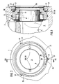
- a working piston 2 which serves as a steering nut and has a rack-like toothing 2A, is slidably mounted in a transmission housing 1.
- the rack-like toothing 2A on the working piston 2 is in engagement with a steering segment 3 of a segment shaft 4.
- the segment shaft 4 is mounted in two eccentrically drilled bearing bushes 5 and 6 via roller bearings 7 and 8.
- the segment shaft 4 can be moved in the direction of the toothing 2A of the working piston 2.
- holes 5A and 6A (FIG. 2) are provided for attaching a tool.
- a pressure chamber 9 of the housing 1 is sealed to the outside by sealing rings 10, 11 or 12, 13.
- the bearing bushes 5 and 6 have ring extensions 14 and 15.
- short grooves 16 and 17 are machined in the housing 1 in the axial direction.
- the ring projections 14 and 15 can be partially caulked in the grooves 16 and 17, so that bulges 18 and 20 arise.
- spring rings 23 and 24 engaging in housing ring grooves 21, 22 are provided.
- the segment shaft bearing is covered with dust caps 25 or 26.
- the bearing bushes 5 and 6 and the spring washers 23 and 24 locking elements 27, 28 with molded lugs 30 and 31.
- the locking elements 27, 28, which are supported radially in recesses 32 and 33 of the bearing bushes 5 and 6, are arranged one so that their lugs 30 and 31 engage under the bulges 18 and 20. It is advantageous for a good system if the lugs 30 and 31 are beveled in accordance with the bulge 18 and 20, respectively. In this way it can be ensured that those present on the ring extensions 14 and 15 Bulges 18 and 20 are deformed under extreme stress.
- the securing elements 27 and 28 carrying the lugs 30 and 31 can be designed as a closed ring (as shown) or as individual segments for each bearing side. In the design as individual segments, an equal number of securing elements can be distributed around the circumference in accordance with the number of grooves 16 and 17.
Landscapes
- Engineering & Computer Science (AREA)
- General Engineering & Computer Science (AREA)
- Mechanical Engineering (AREA)
- Chemical & Material Sciences (AREA)
- Combustion & Propulsion (AREA)
- Transportation (AREA)
- Steering Controls (AREA)
- Power Steering Mechanism (AREA)
- Mounting Of Bearings Or Others (AREA)
- Sealing Devices (AREA)
Abstract
Claims (4)
- Mécanisme de direction pour véhicules, comportant les caractéristiques suivantes:- un carter de boîte (1) comprend un élément d'entraînement qui engrène dans un secteur de direction (3) par une denture;- le secteur de direction (3) est placé sur un arbre à secteur denté (4) ajustable des deux côtés du secteur de direction au moyen de douilles-paliers (5, 6) perçées de façon excentrique;- les douilles-paliers (5, 6) comportent sur leur face frontale libre une saillie annulaire (14, 15) pouvant être partiellement matée dans une ou plusieurs rainures de carter (16, 17) pour empêcher la rotation, de sorte qu'il y ait formation de protubérances à engagement positif (18, 20);- les douilles-paliers sont retenues dans le sens axial par des rondelles élastiques,caractérisé en ce que des tenons (30, 31) intégrés dans un élément de freinage (27, 28) engrènent sous les protubérances (18, 20) des saillies annulaires (14, 15) qui s'avancent dans les rainures de carter (16, 17).
- Mécanisme de direction selon la revendication 1, caractérisé en ce que les tenons (30 et 31) sont biseautés en fonction de la forme de la protubérance (18, voire 20).
- Mécanisme de direction selon la revendication 1, caractérisé en ce que l'élément de freinage (27, 28) est conçu en tant que bague fermée prenant appui dans un évidement (32, 33) de la douille-palier (5, voire 6).
- Mécanisme de direction selon la revendication 1, caractérisé en ce que l'élément de freinage est subdivisé en secteurs séparés en fonction du nombre des protubérances (18, 20).
Applications Claiming Priority (2)
| Application Number | Priority Date | Filing Date | Title |
|---|---|---|---|
| DE3914272 | 1989-04-29 | ||
| DE3914272 | 1989-04-29 |
Publications (2)
| Publication Number | Publication Date |
|---|---|
| EP0470114A1 EP0470114A1 (fr) | 1992-02-12 |
| EP0470114B1 true EP0470114B1 (fr) | 1993-12-01 |
Family
ID=6379796
Family Applications (1)
| Application Number | Title | Priority Date | Filing Date |
|---|---|---|---|
| EP90906205A Expired - Lifetime EP0470114B1 (fr) | 1989-04-29 | 1990-04-24 | Mecanisme de direction pour vehicules |
Country Status (4)
| Country | Link |
|---|---|
| EP (1) | EP0470114B1 (fr) |
| DE (1) | DE59003714D1 (fr) |
| ES (1) | ES2047326T3 (fr) |
| WO (1) | WO1990013464A1 (fr) |
Families Citing this family (4)
| Publication number | Priority date | Publication date | Assignee | Title |
|---|---|---|---|---|
| RU2248900C2 (ru) * | 2000-10-04 | 2005-03-27 | Закрытое акционерное общество "Первомайский механический завод" | Зубчатая передача рулевого привода |
| RU2295795C2 (ru) * | 2005-04-26 | 2007-03-20 | Открытое акционерное общество "Всероссийский научно-исследовательский и проектно-конструкторский институт электровозостроения" (ОАО "ВЭлНИИ") | Многопозиционный переключатель |
| RU2350504C1 (ru) * | 2007-08-20 | 2009-03-27 | Производственное республиканское унитарное предприятие "Минский автомобильный завод" (РУП "МАЗ") | Рулевой механизм транспортного средства с гидроусилителем |
| KR20170073921A (ko) * | 2015-12-21 | 2017-06-29 | 주식회사 만도 | 자동차의 감속기 |
Family Cites Families (5)
| Publication number | Priority date | Publication date | Assignee | Title |
|---|---|---|---|---|
| US4226431A (en) * | 1978-03-09 | 1980-10-07 | Parker-Hannifin Corporation | Sealing device for screw threads |
| DE3017736C2 (de) * | 1980-04-10 | 1984-10-31 | Zahnradfabrik Friedrichshafen Ag, 7990 Friedrichshafen | Lenkgetriebe für Fahrzeuge |
| DE3013855C2 (de) * | 1980-04-10 | 1985-10-31 | Zahnradfabrik Friedrichshafen Ag, 7990 Friedrichshafen | Lenkgetriebe |
| DE3238740C2 (de) * | 1982-10-20 | 1984-10-11 | Zahnradfabrik Friedrichshafen Ag, 7990 Friedrichshafen | Lenkgetriebe für Fahrzeuge |
| EP0379490B1 (fr) * | 1987-08-05 | 1992-03-18 | ZF FRIEDRICHSHAFEN Aktiengesellschaft | Agencement d'un train d'engrenages coniques dans un carter d'engrenages |
-
1990
- 1990-04-24 ES ES90906205T patent/ES2047326T3/es not_active Expired - Lifetime
- 1990-04-24 EP EP90906205A patent/EP0470114B1/fr not_active Expired - Lifetime
- 1990-04-24 WO PCT/EP1990/000655 patent/WO1990013464A1/fr not_active Ceased
- 1990-04-24 DE DE90906205T patent/DE59003714D1/de not_active Expired - Fee Related
Also Published As
| Publication number | Publication date |
|---|---|
| DE59003714D1 (de) | 1994-01-13 |
| EP0470114A1 (fr) | 1992-02-12 |
| WO1990013464A1 (fr) | 1990-11-15 |
| ES2047326T3 (es) | 1994-02-16 |
Similar Documents
| Publication | Publication Date | Title |
|---|---|---|
| DE69108688T2 (de) | Ausgleichsgetriebeeinheit mit schwimmenden Tellerrad. | |
| DE102008009107B4 (de) | Mechanisches Untersetzungsgetriebe mit Schnecke und Schneckenrad | |
| EP4359172B1 (fr) | Outil dynamométrique | |
| DE1215010B (de) | Lenkgetriebe fuer Kraftfahrzeuge | |
| EP1298353B1 (fr) | Engrenage et son utilisation | |
| DE3411054C2 (fr) | ||
| DE3238740C2 (de) | Lenkgetriebe für Fahrzeuge | |
| EP0435969B1 (fr) | Commande oscillante, notamment pour essuie-glace de vehicules a moteur | |
| EP3966072B1 (fr) | Ferrure pour un siège de véhicule | |
| EP0470114B1 (fr) | Mecanisme de direction pour vehicules | |
| EP1334295B1 (fr) | Differentiel destine a l'entrainement d'axe d'un vehicule | |
| EP3477157A1 (fr) | Blocage du différentiel | |
| EP0427983A1 (fr) | Volant d'inertie en deux parties avec dispositif d'amortissement à ressorts | |
| DE10331129B4 (de) | Auswuchtmaschine mit einer Spanneinrichtung | |
| DE20104777U1 (de) | Zahnrad für eine spielfreie Stirnradstufe | |
| DE4012936A1 (de) | Lenkgetriebe fuer fahrzeuge | |
| DE102020200285A1 (de) | Schneckengetriebe | |
| DE102019212221A1 (de) | Wellgetriebe | |
| DE4422492A1 (de) | Motor mit einem Umlaufgetriebe | |
| EP1085239A2 (fr) | Différentiel à pignons coniques pour vehicules utilitaires | |
| EP0392063A1 (fr) | Manivelle à suppression de point mort | |
| DE102017223019A1 (de) | Verzahnungsanordnung | |
| EP0632772A1 (fr) | Soupape a tiroir rotatif pour directions assistees de vehicules a moteur. | |
| DE19903850B4 (de) | Rastvorrichtung für die Lagefixierung der Dreh- oder Längsbewegung einer Schaltwelle | |
| DE2735100A1 (de) | Axialschub-sicherungsanordnung |
Legal Events
| Date | Code | Title | Description |
|---|---|---|---|
| PUAI | Public reference made under article 153(3) epc to a published international application that has entered the european phase |
Free format text: ORIGINAL CODE: 0009012 |
|
| AK | Designated contracting states |
Kind code of ref document: A1 Designated state(s): DE ES GB |
|
| 17P | Request for examination filed |
Effective date: 19910715 |
|
| RAP3 | Party data changed (applicant data changed or rights of an application transferred) |
Owner name: ZF FRIEDRICHSHAFEN AKTIENGESELLSCHAFT |
|
| 17Q | First examination report despatched |
Effective date: 19921112 |
|
| GRAA | (expected) grant |
Free format text: ORIGINAL CODE: 0009210 |
|
| AK | Designated contracting states |
Kind code of ref document: B1 Designated state(s): DE ES GB |
|
| GBT | Gb: translation of ep patent filed (gb section 77(6)(a)/1977) |
Effective date: 19931209 |
|
| REF | Corresponds to: |
Ref document number: 59003714 Country of ref document: DE Date of ref document: 19940113 |
|
| REG | Reference to a national code |
Ref country code: ES Ref legal event code: FG2A Ref document number: 2047326 Country of ref document: ES Kind code of ref document: T3 |
|
| PLBE | No opposition filed within time limit |
Free format text: ORIGINAL CODE: 0009261 |
|
| STAA | Information on the status of an ep patent application or granted ep patent |
Free format text: STATUS: NO OPPOSITION FILED WITHIN TIME LIMIT |
|
| 26N | No opposition filed | ||
| PGFP | Annual fee paid to national office [announced via postgrant information from national office to epo] |
Ref country code: GB Payment date: 20010323 Year of fee payment: 12 |
|
| REG | Reference to a national code |
Ref country code: GB Ref legal event code: IF02 |
|
| PG25 | Lapsed in a contracting state [announced via postgrant information from national office to epo] |
Ref country code: GB Free format text: LAPSE BECAUSE OF NON-PAYMENT OF DUE FEES Effective date: 20020424 |
|
| GBPC | Gb: european patent ceased through non-payment of renewal fee |
Effective date: 20020424 |
|
| PGFP | Annual fee paid to national office [announced via postgrant information from national office to epo] |
Ref country code: ES Payment date: 20080520 Year of fee payment: 19 Ref country code: DE Payment date: 20080502 Year of fee payment: 19 |
|
| PG25 | Lapsed in a contracting state [announced via postgrant information from national office to epo] |
Ref country code: DE Free format text: LAPSE BECAUSE OF NON-PAYMENT OF DUE FEES Effective date: 20091103 |
|
| REG | Reference to a national code |
Ref country code: ES Ref legal event code: FD2A Effective date: 20090425 |
|
| PG25 | Lapsed in a contracting state [announced via postgrant information from national office to epo] |
Ref country code: ES Free format text: LAPSE BECAUSE OF NON-PAYMENT OF DUE FEES Effective date: 20090425 |