EP0470132B1 - Game of darts - Google Patents
Game of darts Download PDFInfo
- Publication number
- EP0470132B1 EP0470132B1 EP90906778A EP90906778A EP0470132B1 EP 0470132 B1 EP0470132 B1 EP 0470132B1 EP 90906778 A EP90906778 A EP 90906778A EP 90906778 A EP90906778 A EP 90906778A EP 0470132 B1 EP0470132 B1 EP 0470132B1
- Authority
- EP
- European Patent Office
- Prior art keywords
- hit
- sector
- playing apparatus
- target
- accordance
- Prior art date
- Legal status (The legal status is an assumption and is not a legal conclusion. Google has not performed a legal analysis and makes no representation as to the accuracy of the status listed.)
- Revoked
Links
- 230000000007 visual effect Effects 0.000 claims description 2
- 230000004397 blinking Effects 0.000 claims 1
- 230000001419 dependent effect Effects 0.000 claims 1
- 230000001960 triggered effect Effects 0.000 claims 1
- 230000003287 optical effect Effects 0.000 abstract description 11
- 239000003086 colorant Substances 0.000 description 2
- 238000010276 construction Methods 0.000 description 1
- 238000001514 detection method Methods 0.000 description 1
- 230000000694 effects Effects 0.000 description 1
- 238000011156 evaluation Methods 0.000 description 1
- 238000005286 illumination Methods 0.000 description 1
Images


Classifications
-
- F—MECHANICAL ENGINEERING; LIGHTING; HEATING; WEAPONS; BLASTING
- F41—WEAPONS
- F41J—TARGETS; TARGET RANGES; BULLET CATCHERS
- F41J5/00—Target indicating systems; Target-hit or score detecting systems
- F41J5/04—Electric hit-indicating systems; Detecting hits by actuation of electric contacts or switches
- F41J5/052—Targets comprising a plurality of electric contacts, each corresponding to a discrete target section and being actuated by the movement thereof
Definitions
- the invention relates to a dart game device with a target mounted on a front plate and a hit display, in which in the end region or adjacent to the end, preferably, each sector of the target, at least one hit display comprising lighting devices is arranged or formed on or in the front plate, which when hit changed their respective brightness value or brightness state in the associated sector.
- the aim of the invention is to improve the visual appearance of the dart game device, to make it easier or more difficult for the player to acquire the target in certain game situations, and at the same time to provide a clearly recognizable and assignable indication of the success of throws, and to increase the number of play options.
- the hit display which is preferably formed by at least one illuminated field, by a microprocessor-controlled control unit as a function of selectable game programs stored in the control unit upon a hit in the associated sector of the illuminated state, optionally via a Intermediate position, namely a flashing or darkened state, can be put into a switched-off state.
- a new feature of the dart game device is that the illuminated display fields located immediately outside the individual sectors can be switched off by hits in the individual sectors or can be converted into a darkened or flashing state and can be switched off completely on the next hit; this type of game is made possible by a control unit scanning the sectors or the hits in the individual sectors, in which corresponding game programs are present.
- the target display which is illuminated
- the shooter is given a target aid or a request to shoot into the displayed sector.
- this creates a new type of game, and on the other hand it improves accuracy and increases the player's desire to play. If the lighting device is dimmed or flashes, another hit in this sector is required, If the lighting device is dark, the player knows that, according to the game selected, he no longer has to hit this sector and can then search for further sectors as the target, supported by the target aids that are still illuminated, ie the hit displays.
- the brightness value can therefore be changed in one or two steps.
- each hit display Due to the hit display located in the extension area of each sector of the target, the shooter can draw a connecting line from the hit display to the center of the target and thus improve the accuracy, since it is known that aiming and throwing along a line or elongated sector leads to hits more easily than point by point Aim.
- each hit display is also clearly assigned to a sector and can, e.g. with a number appearing on the hit display, show the value of the sector.
- a simple construction results if the front panel is printed on the inside and has cutouts in the print at the places of the hit displays, with lamps, light-emitting diodes (LED) or the like behind the recessed locations on the front panel. are arranged, which are controlled by a control unit or supplied with current.
- LED light-emitting diodes
- the illuminated fields are visually spectacular and flash depending on the type of hit or are illuminated in sequence or made to go out or at the same time flash together or the like. Fields with different colors are also possible, e.g. by arranging different colored lamps, light emitting diodes or the like.
- the individual sectors of the hit display are assigned electrical contacts or are arranged within the sectors which are located in particular between the sectors formed by movably mounted plates and a support plate or circuit board of the hit display, which contacts when a dart hits are closable and scanned by the control unit.
- the lighting unit e.g. Incandescent lamp, LED or the like.
- the control unit effects the switching off, switching on and flashing or the successive lighting up of the hit displays.
- the center area of the target is illuminated with an illumination device which can be influenced or switched by hits, in particular in the center.
- the optical displays or light fields provided in the front panel can have different shapes; the light fields can be triangular, square, round, trapezoidal, circular sector-shaped, in Lightning or other geometric shapes. It is also possible to use lighting devices, for example lamps, light-emitting diodes or the like, in the form of a cross, in the form of circles, triangles or the like. to arrange.
- FIG. 1 shows a front view of a target with hit display
- FIG. 2 schematically shows a section through a target with a control device
- FIG. 1 shows a target 2 intended for dart games, which is known to be divided into several sectors 4, the end regions of which are followed by an optical hit display 3 radially outward.
- the hit displays 3 e.g. directly after the individual sectors 4 and be provided with numbers or the numbers can be located between the sectors 4 and the optical hit displays 3. It is also possible to arrange the numbers radially outside the optical hit displays 3.
- the optical hit displays can have a variety of shapes and can be formed by a full luminous area or a plurality of luminous areas or dots which may also have different sizes or shapes.
- Illuminated displays in the form of illuminated numbers or numbers could also be provided per se.
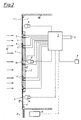
- the target 2 shows a section through a target 2, which is inserted into the front plate 1 of a housing 20, which is optionally designed as a standing housing.
- the target 2 comprises a circuit board 2 'which carries the plates forming the individual sectors 4, which run between webs 4' which separate the individual sectors from one another (FIG. 1).
- Electrical contacts 5 are arranged between the circuit board 2 'and the plates 4 and are electrically conductively connected by the plate 4 when a dart hits.
- sensors can also be provided which emit an electrical signal when the plate 4 is acted upon by the impact of a dart.
- Other solutions are also conceivable.
- the contacts 5 or the sensors are connected to a control unit 7, which recognizes from which plate 4 the corresponding signals come and then controls the optical hit displays, in the illustrated case lighting devices, for example incandescent lamps 6, in a corresponding manner.
- the light bulbs 6 are located on the inside of the front panel 1, wherein in this area the print 1 ', which is usually applied on the inside, is left out, which can be attached in order to give the front panel a desired color or graphic design.
- the control unit 7 is supplied with power by means of a schematically illustrated current source 9.
- An input unit 8 is provided, with which the player of the control unit 7 can specify certain functions, e.g. whether the control unit should switch the lighting device on or off in the event of a hit.
- a lighting device 6 'illuminating the center 13 of the target 2 makes it easier to aim when the target is aimed at the space between the optical hit displays arranged around the edge of the target and this central lighting device.
- FIG. 3 shows a mechanical display device which is formed by a number of disks 14 arranged on rods, which can have different colors.
- the ink discs 14 are driven by a motor 11, which is activated or stopped by the control device 7.
- different color displays can thus be adjusted in front of the recess in the print 1 'on the rear of the front panel 1.
- a circular ring with different color fields could be provided, which can turn past the recess.
- FIG. 4 shows a further embodiment for optical hit displays.
- a plate 15 is mounted about axes 16; the end of the (angle) lever 17 carrying the plate 15 can be attracted or adjusted by an electromagnet 7 which is actuated by the control device 7.
- an electromagnet 7 which is actuated by the control device 7.
- FIG. 5 shows an arrangement in which, with the rollers 11 driven by the motor 11, an illuminable film tape 18 with different color areas or images can be moved past the recess 1 ′′ in the front plate 1 and has changing optical displays controlled by the control device 7.
- hit display or the housing 20 in FIG. 2 are in the area 21 the hit count displays usually provided in such devices, money slots, type selector switches, type displays, screens, etc.
- hit count displays usually provided in such devices, money slots, type selector switches, type displays, screens, etc.
- Hit displays 3,3 ', 3'',3''' are provided or arranged around the circumference of the target.
- the control unit 7 which is usually microprocessor-controlled, switches the illuminated fields or optical hit displays depending on the hits and the game program and also controls the other (hit) displays, (hit) numerical displays and sequence functions, which are shown schematically in the form of a unit and are designated by 22.
- the lighting device for the central region (13) is also switched by the control device (7).
Landscapes
- Engineering & Computer Science (AREA)
- General Engineering & Computer Science (AREA)
- Illuminated Signs And Luminous Advertising (AREA)
- Pinball Game Machines (AREA)
- Aiming, Guidance, Guns With A Light Source, Armor, Camouflage, And Targets (AREA)
- Devices For Checking Fares Or Tickets At Control Points (AREA)
- Input Circuits Of Receivers And Coupling Of Receivers And Audio Equipment (AREA)
Abstract
Description
Die Erfindung betrifft ein Wurfpfeilspielgerät mit einer auf einer Frontplatte montierten Zielscheibe und einer Trefferanzeige, bei dem im Endbereich bzw. benachbart dem Ende vorzugsweise jedes Sektors der Zielscheibe zumindest eine Beleuchtungseinrichtungen umfassende Trefferanzeige angeordnet bzw. auf oder in der Frontplatte ausgebildet ist, die bei einem Treffer in den zugehörigen Sektor ihren jeweiligen Helligkeitswert bzw. Helligkeitszustand verändert.The invention relates to a dart game device with a target mounted on a front plate and a hit display, in which in the end region or adjacent to the end, preferably, each sector of the target, at least one hit display comprising lighting devices is arranged or formed on or in the front plate, which when hit changed their respective brightness value or brightness state in the associated sector.
Aus der US-PS 2 501 218 ist ein derartiges Wurfpfeilspielgerät bekannt. Bei dem in dieser Druckschrift beschriebenen Wurfpfeilspielgerät werden Lampen bei einem Treffer erhellt.Such a dart game device is known from US Pat. No. 2,501,218. In the dart game device described in this publication, lamps are illuminated when hit.
Ziel der Erfindung ist es, das optische Erscheinungsbild des Wurfpfeilspielgerätes zu verbessern, dem Spieler die Zielerfassung in gewissen Spielsituationen zu erleichtern oder zu erscheren und gleichzeitig eine gut erkennbare und zuordenbare Anzeige über den Erfolg von Würfen zu geben, sowie die Anzahl der Spielmöglichkeiten zu erhöhen.The aim of the invention is to improve the visual appearance of the dart game device, to make it easier or more difficult for the player to acquire the target in certain game situations, and at the same time to provide a clearly recognizable and assignable indication of the success of throws, and to increase the number of play options.
Diese Ziele werden bei einem Wurfpfeilspielgerät der eingangs genannten Art dadurch erreicht, daß die vorzugsweise von zumindest einem beleuchteten Feld gebildete Trefferanzeige von einer mikroprozessorgesteuerten Steuereinheit in Abhängigkeit von auswählbaren in der Steuereinheit gespeicherten Spielprogrammen bei einem Treffer in den zugehörigen Sektor von dem beleuchteten Zustand gegebenenfalls über eine Zwischenstellug, nämlich einen blinkenden oder abgedunkelten Zustand, in einen abgeschalteten Zustand versetzbar ist. Neuartig bei dem erfindungsgsgemäßen Wurfpfeilspielgerät ist es, daß die unmittelbar außerhalb der einzelnen Sektoren liegenden beleuchteten Anzeigefelder durch Treffer in die einzelnen Sektoren ausgeschaltet bzw. in einen abgedunkelten bzw. blinkenden Zustand übergeführt und beim nächsten Treffer vollständig ausgeschaltet werden können; diese Spielart wird durch eine die Sektoren bzw. die Treffer in den einzelnen Sektoren abtastende Steuereinheit ermöglicht, in der entsprechende Spielprogramme vorhanden sind.These goals are achieved in a dart game device of the type mentioned at the outset in that the hit display, which is preferably formed by at least one illuminated field, by a microprocessor-controlled control unit as a function of selectable game programs stored in the control unit upon a hit in the associated sector of the illuminated state, optionally via a Intermediate position, namely a flashing or darkened state, can be put into a switched-off state. A new feature of the dart game device according to the invention is that the illuminated display fields located immediately outside the individual sectors can be switched off by hits in the individual sectors or can be converted into a darkened or flashing state and can be switched off completely on the next hit; this type of game is made possible by a control unit scanning the sectors or the hits in the individual sectors, in which corresponding game programs are present.
Damit wird erreicht, daß durch die in Verlängerungsbereich jedes Sektors der Zielscheibe gelegene Trefferanzeige, welche beleuchtet ist, dem Schützen eine Zielhilfe bzw. eine Aufforderung abgegeben wird, in den angezeigten Sektor hineinzuschießen. Einerseits wird dadurch ein neuartiges Spiel erstellt und anderseits wird dadurch die Treffsicherheit verbessert und die Lust des Spielers am Spiel erhöht. Ist die Beleuchtungseinrichtung abgedunkelt bzw. blinkt sie, so ist ein weiterer Treffer in diesen Sektor erforderlich, ist die Beleuchtungseinrichtung dunkel, so weiß der Spieler, daß er entsprechend dem ausgesuchten Spiel diesen Sekor nicht mehr treffen muß und kann sich dann, unterstützt durch die noch beleuchteten Zielhilfen, d.h. die Trefferanzeigen, weitere Sektoren als Ziel suchen. Die Änderung des Helligkeitswertes kann somit in einem oder in zwei Schritten erfolgen.This ensures that the target display, which is illuminated, is located in the extension area of each sector of the target and is illuminated, and the shooter is given a target aid or a request to shoot into the displayed sector. On the one hand, this creates a new type of game, and on the other hand it improves accuracy and increases the player's desire to play. If the lighting device is dimmed or flashes, another hit in this sector is required, If the lighting device is dark, the player knows that, according to the game selected, he no longer has to hit this sector and can then search for further sectors as the target, supported by the target aids that are still illuminated, ie the hit displays. The brightness value can therefore be changed in one or two steps.
Durch die im Verlängungsbereich jedes Sektors der Zielscheibe gelegene Trefferanzeige kann vom Schützen eine Verbindungslinie von der Trefferanzeige zum Mittelpunkt der Zielscheibe gezogen werden und damit die Treffsicherheit verbessert werden, da bekanntermaßen das Zielen und Werfen längs einer Linie bzw. länglichen Sektors leichter zu Treffern führt als punktweises Zielen. Auf diese Weise ist ferner auch jede Trefferanzeige eindeutig einem Sekor zugeordnet und kann, z.B. mit einer auf der Trefferanzeige aufscheinenden Nummer, den Wert des Sektors anzeigen. Schließlich kann vorgesehen sein, daß durch regelmäßig oder unregelmäßig aufeinanderfolgendes Blinken der einzelnen Trefferanzeigen, Spieler auf das Gerät aufmerksam gemacht und zum Spielen animiert werden.Due to the hit display located in the extension area of each sector of the target, the shooter can draw a connecting line from the hit display to the center of the target and thus improve the accuracy, since it is known that aiming and throwing along a line or elongated sector leads to hits more easily than point by point Aim. In this way, each hit display is also clearly assigned to a sector and can, e.g. with a number appearing on the hit display, show the value of the sector. Finally, it can be provided that by regularly or irregularly successively flashing the individual hit displays, players are made aware of the device and are encouraged to play.
Ein einfacher Aufbau ergibt sich, wenn die Frontplatte an ihrer Innenseite bedruckt ist und an den Stellen der Trefferanzeigen Aussparungen im Druck aufweist, wobei hinter den ausgesparten Stellen der Frontplatte Lampen, Leuchtdioden (LED) od.dgl. angeordnet sind, die von einer Steuereinheit angesteuert bzw. mit Strom versorgt sind.A simple construction results if the front panel is printed on the inside and has cutouts in the print at the places of the hit displays, with lamps, light-emitting diodes (LED) or the like behind the recessed locations on the front panel. are arranged, which are controlled by a control unit or supplied with current.
Die beleuchteten Felder sind optisch eindrucksvoll gestaltet und blinken je nach Art des Treffers oder werden der Reihe nach beleuchtet bzw. erlöschen gelassen oder blinken gleichzeitig gemeinsam od.dgl. Auch verschiedenfärbig aufleuchtende Felder sind möglich, z.B. durch Anordnung von verschiedenfärbigen Lampen, Leuchtdioden od.dgl.The illuminated fields are visually impressive and flash depending on the type of hit or are illuminated in sequence or made to go out or at the same time flash together or the like. Fields with different colors are also possible, e.g. by arranging different colored lamps, light emitting diodes or the like.
Zweckmäßigerweise ist vorgesehen, daß den einzelnen Sektoren der Trefferanzeige elektrische Kontakte zugeordnet sind bzw. diese innerhalb der Sektoren angeordnet sind, die insbesondere zwischen den von beweglich gelagerten Platten gebildeten Sektoren und einer Tragplatte bzw. Platine der Trefferanzeige gelegen sind, welche Kontakte bei Auftreffen eines Wurfpfeiles schließbar und von der Steuereinheit abgetastet sind. Auf diese Weise ist eine einfache Erfassung des jeweils getroffenen Sektors zur Auswertung möglich und es kann eine einfache Ansteuerung der Beleuchtungseinheit, z.B. Glühlampe, LED od.dgl., erfolgen. Die Steuereinheit bewirkt das Abschalten, das Anschalten und das Blinken bzw. das in bestimmter Aufeinanderfolge erfolgende Aufleuchten der Trefferanzeigen.It is expediently provided that the individual sectors of the hit display are assigned electrical contacts or are arranged within the sectors which are located in particular between the sectors formed by movably mounted plates and a support plate or circuit board of the hit display, which contacts when a dart hits are closable and scanned by the control unit. In this way, a simple detection of the sector hit in each case is possible for evaluation, and the lighting unit, e.g. Incandescent lamp, LED or the like. The control unit effects the switching off, switching on and flashing or the successive lighting up of the hit displays.
Um die Zielgenauigkeit und die Spielvariationen weiter zu verbessern ist vorgesehen, daß der Mittelpunktsbereich der Zielscheibe mit einer Beleuchtungseinrichtung beleuchtet ist, die von Treffern, insbesondere in den Mittelpunkt, beeinflußbar bzw. schaltbar ist.In order to further improve the target accuracy and the game variations, it is provided that the center area of the target is illuminated with an illumination device which can be influenced or switched by hits, in particular in the center.
Die in der Frontplatte vorgesehenen optischen Anzeigen bzw. Leuchtfelder, können verschiedene Form haben; die Leuchtfelder können z.B. dreieckförmig, quadratisch, rund, trapezförmig, kreissektorförmig, in Form von Blitzen oder anderen geometrischen Formen ausgeführt sein. Es ist auch möglich, Leuchteinrichtungen, z.B. Lampen, Leuchtdioden od.dgl., in Kreuzform, in Form von Kreisen, Dreiecken od.dgl. anzuordnen.The optical displays or light fields provided in the front panel can have different shapes; the light fields can be triangular, square, round, trapezoidal, circular sector-shaped, in Lightning or other geometric shapes. It is also possible to use lighting devices, for example lamps, light-emitting diodes or the like, in the form of a cross, in the form of circles, triangles or the like. to arrange.
Im folgenden wird die Erfindung anhand der Zeichnung näher erläutert. Es zeigen Fig .1 eine Vordersicht einer Zielscheibe mit Trefferanzeige, Fig.2 schematisch einen Schnitt durch eine Zielscheibe mit einer Steuereinrichtung und Fig.3,4 und 5 verschiedene Trefferanzeigen.The invention is explained in more detail below with reference to the drawing. 1 shows a front view of a target with hit display, FIG. 2 schematically shows a section through a target with a control device, and FIGS. 3, 4 and 5 different hit displays.
Fig.1 zeigt eine für Wurfpfeilspiele vorgesehene Zielscheibe 2, die bekannterweise in mehrere Sektoren 4 geteilt ist, deren Endbereichen radial nach außen hin jeweils eine optische Trefferanzeige 3 folgt. Wie Fig .1 links zu entnehmen ist, können die Trefferanzeigen 3, z.B. direkt anschließend an die einzelnen Sektoren 4 ausgebildet sein und mit Ziffern versehen sein oder die Ziffern können zwischen den Sektoren 4 und den optischen Trefferanzeigen 3 gelegen sein. Es ist auch möglich, die Ziffern radial außerhalb der optischen Trefferanzeigen 3 anzuordnen.1 shows a
Wie in Fig.1 rechts dargestellt, können die optischen Trefferanzeigen vielfältige Formen besitzen und von einer vollen Leuchtfläche oder einer Mehrzahl von gegebenenfalls auch verschieden großen bzw. verschiedene Form besitzenden Leuchtflächen bzw. -punkten gebildet sein. An sich könnten auch Leuchtanzeigen in Form von aufleuchtenden Ziffern bzw. Zahlen vorgesehen sein.As shown on the right in FIG. 1, the optical hit displays can have a variety of shapes and can be formed by a full luminous area or a plurality of luminous areas or dots which may also have different sizes or shapes. Illuminated displays in the form of illuminated numbers or numbers could also be provided per se.
Fig.2 zeigt einen Schnitt durch eine Zielscheibe 2, die in die Frontplatte 1 eines Gehäuses 20 eingesetzt ist, das gegebenenfalls als Standgehäuse ausgebildet ist. Die Zielscheibe 2 umfaßt eine Platine 2', welche die die einzelnen Sektoren 4 bildende Platten trägt, die zwischen Stege 4' verlaufen, welche die einzelnen Sektoren voneinander trennen (Fig.1). Zwischen der Platine 2' und den Platten 4 sind elektrische Kontakte 5 angeordnet, die durch die Platte 4 bei Auftreffen eines Wurfpfeiles elektrisch leitend verbunden werden. Als Alternative zu diesen elektrischen Kontakten 5 können auch Sensoren vorgesehen sein, die bei einer Kraftbeaufschlagung der Platte 4 durch Anprall eines Wurfpfeiles ein elektrisches Signal abgeben. Auch andere Lösungen sind denkbar. Die Kontakte 5 bzw. die Sensoren sind mit einer Steuereinheit 7 verbunden, welche erkennt, von welcher Platte 4 die entsprechenden Signale stammen und in entsprechender Weise sodann die optischen Trefferanzeigen, im dargestellten Fall Beleuchtungseinrichtungen, z.B. Glühlampen 6, ansteuert. Die Glühlampen 6 befinden sich an der Innenseite der Frontplatte 1, wobei in diesem Bereich der üblicherweise innenseitig angebrachte Aufdruck 1' ausgespart ist, welcher angebracht werden kann, um der Frontplatte eine gewünschte Farbe oder graphische Ausbildung zu verleihen.2 shows a section through a
Die Stromversorgung der Steuereinheit 7 erfolgt mittels einer schematisch dargestellten Stromquelle 9. Eine Eingabeeinheit 8 ist vorgesehen, mit der der Spieler der Steuereinheit 7 bestimmte Funktionen vorgeben kann, z.B. ob die Steuereinheit bei einem Treffer die Beleuchtungseinrichtung ein- oder ausschalten soll.The
Eine den Mittelpunkt 13 der Zielscheibe 2 beleuchtende Beleuchtungsvorrichtung 6' erleichtert das Zielen, wenn auf dem Raum zwischen den um den Rand der Zielscheibe angeordneten optischen Trefferanzeigen und dieser mittleren Beleuchtungseinrichtung gezielt wird.A lighting device 6 'illuminating the
Fig.3 zeigt eine mechanische Anzeigeeinrichtung, die von einer Anzahl von auf Stäben angeordneten Scheiben 14 gebildet ist, welche unterschiedliche Farben besitzen können. Die Farbscheiben 14 werden von einem Motor 11 angetrieben, der von der Steuereinrichtung 7 in Tätigkeit gesetzt bzw. angehalten wird. Damit können je nach Art des Treffers verschiedene Farbanzeigen vor die Ausnehmung im Druck 1' an der Rückseite der Frontplatte 1 verstellt werden. In gleicher Weise könnte ein Kreisring mit verschiedenen Farbfeldern vorgesehen werden, der sich an der Ausnehmung vorbeidrehen kann.3 shows a mechanical display device which is formed by a number of
Fig.4 zeigt eine weitere Ausführungsform für optische Trefferanzeigen. In einer Ausnehmung der Frontplatte 1 ist ein Plättchen 15 um Achsen 16 gelagert; das Ende des das Plättchen 15 tragenden (Winkel)Hebels 17 kann von einem Elektromagneten 7 angezogen bzw. verstellt werden, welcher von der Steuereinrichtung 7 betätigt wird. Durch das Aufklappen des Plättchens 15, das z.B. eine Zahl trägt oder erscheinen läßt, wird eine auffallende Änderung der Oberflächenstruktur der Frontplatte 1 erreicht.4 shows a further embodiment for optical hit displays. In a recess of the
Fig.5 zeigt eine Anordnung, bei der mit von dem Motor 11 angetriebenen Rollen 11 ein beleuchtbares Filmband 18 mit verschiedenen Farbbereichen oder Bildern an der Ausnehmung 1'' in der Frontplatte 1 vorbeibewegt werden kann und von der Steuereinrichtung 7 gesteuert wechselnde optische Anzeigen besitzt.5 shows an arrangement in which, with the
Unterhalb der Trefferanzeige bzw. dem Gehäuse 20 in Fig.2 befinden sich im Bereich 21 die üblicherweise bei derartigen Geräten vorgesehenen Trefferzählanzeigen, Geldeinwurfschlitze, Spielartenwählschalter, Spielartanzeigen, Bildschirme usw. Zusätzlich zu diesen Anzeigen sind die Trefferanzeigen 3,3',3'',3''' vorgesehen bzw. um den Umfang der Zielscheibe herum angeordnet.Below the hit display or the
Möglich wäre es z.B. auch, zwei oder mehr Trefferanzeigen für nebeneinanderliegende Sektoren 4 zusammenzufassen und jeweils die dem entsprechenden Sektor zugeordnete Fläche aufleuchten zu lassen, wie bei 33 für vier Sektoren angedeutet ist. Es ist auch die Anordnung eines Kreisringes um die Zielscheibe herum mit entsprechenden Sektoren 4 zugeordneten beleuchtbaren Sichtflächen möglich.It would be possible e.g. also to combine two or more hit displays for
Die Steuereinheit 7, die in der Regel mikroprozessorgesteuert ist, schaltet die Leuchtfelder bzw. optischen Trefferanzeigen in Abhängigkeit von den Treffern und dem Spielprogramm und steuert auch die übrigen (Treffer) Anzeigen, (Treffer)Ziffernanzeigen und Ablauffunktionen, die schematisch in Form einer Einheit dargestellt und mit 22 bezeichnet sind. Auch die Beleuchtungseinrichtung für den Mittelpunktsbereich (13) wird von der Steuereinrichtung (7) geschaltet.The
Claims (7)
- Darts playing apparatus having both a target mounted on a front plate and a hit indicator, with which playing apparatus at least one hit indicator (3, 3',3'',3''') comprising illuminating devices is arranged in the end region or adjacent to the end of preferably each sector (4) of the target (2) or is - in the end region or adjacent to the end of preferably each sector (4) of the target (2) - constructed on or in the front plate (1), this hit indicator (3,3',3'', 3''') altering its present brightness value or brightness state when the associated sector (4) is hit, characterised in that the hit indicator - preferably formed from at least one illuminated field (3) - can - by means of a microprocessor-controlled control unit (7) and dependent on selectable game programmes stored in the control unit (7) - be changed from the illuminated state to a switched-off state - optionally via an intermediate position, namely a blinking or dimmed state - when the associated sector (4) is hit.
- Playing apparatus in accordance with Claim 1, characterised in that the front plate (1) is printed on its inner side (1') and has recesses in the print (1') at the sites of the hit indicators (3, 3', 3'', 3'''), behind the recessed sites of the front plate (1) there being arranged the illuminating devices, e.g. lamps, light-emitting diodes or the like, which are triggered or supplied with current by the control unit (7).
- Playing apparatus in accordance with Claim 1 or 2, characterised in that electrical contacts (5) are associated with the individual sectors (4) of the hit indicator (1) or are arranged within the sectors (4), these electrical contacts being located in particular between the sectors (4) formed by movably mounted plates and a bearing plate or board of the hit indicator (2) [sic], being closable in the event of a dart hit and this being sensed by the control unit (7) for the purposes of dimming or switching-off the hit indicator (3) of this sector (4).
- Playing apparatus in accordance with any one of Claims 1 to 3, characterised in that at least one hit indicator (3, 3', 3'', 3''') is located in the radial extension of each sector (4).
- Playing apparatus in accordance with any one of Claims 1 to 4, characterised in that the bulls eye region (13) of the target (2) is illuminated by an illuminating device (6').
- Playing apparatus in accordance with any one of Claims 1 to 5, characterised in that the hit indicators, in particular the luminous fields (3), are provided with numbers.
- Playing apparatus in accordance with any one of Claims 1 to 6, characterised in that the visual hit indicators or those formed by luminous fields are provided in addition to other display devices enumerating the hits or indicating the hits figure.
Applications Claiming Priority (3)
| Application Number | Priority Date | Filing Date | Title |
|---|---|---|---|
| DE3913787 | 1989-04-26 | ||
| DE3913787A DE3913787A1 (en) | 1989-04-26 | 1989-04-26 | THROWING ARROW PLAYER |
| PCT/AT1990/000040 WO1990012995A1 (en) | 1989-04-26 | 1990-04-26 | Game of darts |
Publications (2)
| Publication Number | Publication Date |
|---|---|
| EP0470132A1 EP0470132A1 (en) | 1992-02-12 |
| EP0470132B1 true EP0470132B1 (en) | 1994-06-22 |
Family
ID=6379520
Family Applications (1)
| Application Number | Title | Priority Date | Filing Date |
|---|---|---|---|
| EP90906778A Revoked EP0470132B1 (en) | 1989-04-26 | 1990-04-26 | Game of darts |
Country Status (5)
| Country | Link |
|---|---|
| EP (1) | EP0470132B1 (en) |
| AT (1) | ATE107766T1 (en) |
| CA (1) | CA2053248A1 (en) |
| DE (2) | DE3913787A1 (en) |
| WO (1) | WO1990012995A1 (en) |
Cited By (1)
| Publication number | Priority date | Publication date | Assignee | Title |
|---|---|---|---|---|
| US9192837B2 (en) | 2012-09-27 | 2015-11-24 | Eastpoint Sports Ltd., Llc | Lawn dart, lawn dart caddy and target |
Families Citing this family (4)
| Publication number | Priority date | Publication date | Assignee | Title |
|---|---|---|---|---|
| EP0689029B1 (en) * | 1994-06-21 | 2001-07-25 | Miguel Angel Quetglas Arino | Illuminated dartboard |
| ES2107335B1 (en) * | 1994-06-21 | 1998-07-01 | Arino Miguel Angel Quetglas | IMPROVEMENTS INTRODUCED IN THE CONSTRUCTION OF ELECTRONIC TARGETS. |
| KR101627263B1 (en) * | 2014-11-21 | 2016-06-03 | 주식회사 홍인터내셔날 | Dart board equipped light source and control device thereof |
| DE102021113702A1 (en) | 2021-05-27 | 2022-12-01 | Tim Schneckenburger | aim assist device |
Family Cites Families (6)
| Publication number | Priority date | Publication date | Assignee | Title |
|---|---|---|---|---|
| BE444641A (en) * | ||||
| US2168644A (en) * | 1936-10-14 | 1939-08-08 | Albert E Browning | Target indicating game |
| US2501218A (en) * | 1948-06-24 | 1950-03-21 | Hill John Harry | Electric dart board |
| CH282422A (en) * | 1950-03-06 | 1952-04-30 | Bihlmaier Karl | Indoor shooting range. |
| US2693959A (en) * | 1952-01-31 | 1954-11-09 | Jr Alexander D Ross | Target apparatus with electrical indicator |
| US4516781A (en) * | 1982-11-17 | 1985-05-14 | Industrial Design Electronic Associates, Inc. | Dart game with two microcomputers |
-
1989
- 1989-04-26 DE DE3913787A patent/DE3913787A1/en not_active Withdrawn
-
1990
- 1990-04-26 CA CA002053248A patent/CA2053248A1/en not_active Abandoned
- 1990-04-26 EP EP90906778A patent/EP0470132B1/en not_active Revoked
- 1990-04-26 WO PCT/AT1990/000040 patent/WO1990012995A1/en not_active Ceased
- 1990-04-26 DE DE59006243T patent/DE59006243D1/en not_active Revoked
- 1990-04-26 AT AT90906778T patent/ATE107766T1/en not_active IP Right Cessation
Cited By (1)
| Publication number | Priority date | Publication date | Assignee | Title |
|---|---|---|---|---|
| US9192837B2 (en) | 2012-09-27 | 2015-11-24 | Eastpoint Sports Ltd., Llc | Lawn dart, lawn dart caddy and target |
Also Published As
| Publication number | Publication date |
|---|---|
| WO1990012995A1 (en) | 1990-11-01 |
| ATE107766T1 (en) | 1994-07-15 |
| EP0470132A1 (en) | 1992-02-12 |
| DE59006243D1 (en) | 1994-07-28 |
| DE3913787A1 (en) | 1990-11-08 |
| CA2053248A1 (en) | 1990-10-27 |
Similar Documents
| Publication | Publication Date | Title |
|---|---|---|
| EP2263047B1 (en) | Cooking hob with switching arrangement | |
| DE112016005651T5 (en) | Display device and game machine | |
| EP0382879A1 (en) | Pointer instrument | |
| EP0341247B1 (en) | Amusement machine with darts | |
| EP0953138A1 (en) | Device for determining the point of impact of darts on a practice target | |
| DE102007014264A1 (en) | Light-switch position indicator | |
| DE68902708T3 (en) | Analog indicator with luminous pointer and limit indication. | |
| EP0470132B1 (en) | Game of darts | |
| DE4002126C2 (en) | Dart game device | |
| DE19807483B4 (en) | pointer instrument | |
| EP1906219B1 (en) | Device for evacuating persons | |
| EP1633597B1 (en) | Illumination device for motor vehicles, comprising a lamp module provided with light-emitting diodes | |
| DE19939004A1 (en) | Display instrument with a pointer | |
| DE3806217A1 (en) | All-round luminaire | |
| DE69521847T2 (en) | Illuminated dart target | |
| DE19748522A1 (en) | Signalling device using LED display for traffic lights | |
| DE4244452C2 (en) | Display instrument for motor vehicles | |
| DE8916066U1 (en) | Dart game device | |
| EP1665593B1 (en) | Slide control for an audio mixer | |
| EP0619870B1 (en) | Darts game | |
| DE102007060243A1 (en) | tracking device | |
| DE8701185U1 (en) | Dart game device | |
| DE3122477C2 (en) | ||
| DE619012C (en) | Device for displaying and acknowledging switching processes, in particular in an illuminated circuit diagram | |
| DE19714039A1 (en) | Illuminated decorative article |
Legal Events
| Date | Code | Title | Description |
|---|---|---|---|
| PUAI | Public reference made under article 153(3) epc to a published international application that has entered the european phase |
Free format text: ORIGINAL CODE: 0009012 |
|
| 17P | Request for examination filed |
Effective date: 19911007 |
|
| AK | Designated contracting states |
Kind code of ref document: A1 Designated state(s): AT BE CH DE DK ES FR GB IT LI LU NL SE |
|
| 17Q | First examination report despatched |
Effective date: 19930830 |
|
| GRAA | (expected) grant |
Free format text: ORIGINAL CODE: 0009210 |
|
| ITF | It: translation for a ep patent filed | ||
| AK | Designated contracting states |
Kind code of ref document: B1 Designated state(s): AT BE CH DE DK ES FR GB IT LI LU NL SE |
|
| PG25 | Lapsed in a contracting state [announced via postgrant information from national office to epo] |
Ref country code: NL Effective date: 19940622 Ref country code: FR Effective date: 19940622 Ref country code: DK Effective date: 19940622 Ref country code: BE Effective date: 19940622 |
|
| REF | Corresponds to: |
Ref document number: 107766 Country of ref document: AT Date of ref document: 19940715 Kind code of ref document: T |
|
| REF | Corresponds to: |
Ref document number: 59006243 Country of ref document: DE Date of ref document: 19940728 |
|
| GBT | Gb: translation of ep patent filed (gb section 77(6)(a)/1977) |
Effective date: 19940805 |
|
| PG25 | Lapsed in a contracting state [announced via postgrant information from national office to epo] |
Ref country code: SE Effective date: 19940922 |
|
| PG25 | Lapsed in a contracting state [announced via postgrant information from national office to epo] |
Ref country code: ES Free format text: LAPSE BECAUSE OF FAILURE TO SUBMIT A TRANSLATION OF THE DESCRIPTION OR TO PAY THE FEE WITHIN THE PRESCRIBED TIME-LIMIT Effective date: 19940923 |
|
| EN | Fr: translation not filed | ||
| PLBI | Opposition filed |
Free format text: ORIGINAL CODE: 0009260 |
|
| NLV1 | Nl: lapsed or annulled due to failure to fulfill the requirements of art. 29p and 29m of the patents act | ||
| 26 | Opposition filed |
Opponent name: CONTINENTAL DARK ROSTONGELA, S.L. Effective date: 19941130 Opponent name: DARYDE, S.L. Effective date: 19941130 |
|
| PG25 | Lapsed in a contracting state [announced via postgrant information from national office to epo] |
Ref country code: LU Free format text: LAPSE BECAUSE OF NON-PAYMENT OF DUE FEES Effective date: 19950430 Ref country code: LI Effective date: 19950430 Ref country code: CH Effective date: 19950430 |
|
| REG | Reference to a national code |
Ref country code: CH Ref legal event code: PL |
|
| PGFP | Annual fee paid to national office [announced via postgrant information from national office to epo] |
Ref country code: GB Payment date: 19980312 Year of fee payment: 9 |
|
| PGFP | Annual fee paid to national office [announced via postgrant information from national office to epo] |
Ref country code: DE Payment date: 19980318 Year of fee payment: 9 |
|
| PGFP | Annual fee paid to national office [announced via postgrant information from national office to epo] |
Ref country code: AT Payment date: 19980414 Year of fee payment: 9 |
|
| PLBQ | Unpublished change to opponent data |
Free format text: ORIGINAL CODE: EPIDOS OPPO |
|
| PLAB | Opposition data, opponent's data or that of the opponent's representative modified |
Free format text: ORIGINAL CODE: 0009299OPPO |
|
| RDAH | Patent revoked |
Free format text: ORIGINAL CODE: EPIDOS REVO |
|
| R26 | Opposition filed (corrected) |
Opponent name: DARYDE, S.L. * 19941130 CONTINENTAL DARK ROSTONGEL Effective date: 19941130 |
|
| RDAG | Patent revoked |
Free format text: ORIGINAL CODE: 0009271 |
|
| STAA | Information on the status of an ep patent application or granted ep patent |
Free format text: STATUS: PATENT REVOKED |
|
| 27W | Patent revoked |
Effective date: 19990401 |
|
| GBPR | Gb: patent revoked under art. 102 of the ep convention designating the uk as contracting state |
Free format text: 990401 |