EP0470142B1 - Equipment for filling a container with a divided solid product - Google Patents
Equipment for filling a container with a divided solid product Download PDFInfo
- Publication number
- EP0470142B1 EP0470142B1 EP90907099A EP90907099A EP0470142B1 EP 0470142 B1 EP0470142 B1 EP 0470142B1 EP 90907099 A EP90907099 A EP 90907099A EP 90907099 A EP90907099 A EP 90907099A EP 0470142 B1 EP0470142 B1 EP 0470142B1
- Authority
- EP
- European Patent Office
- Prior art keywords
- plate
- tube
- solids
- radius
- plates
- Prior art date
- Legal status (The legal status is an assumption and is not a legal conclusion. Google has not performed a legal analysis and makes no representation as to the accuracy of the status listed.)
- Expired - Lifetime
Links
- 239000012265 solid product Substances 0.000 title abstract description 3
- 239000007787 solid Substances 0.000 claims abstract description 42
- 239000006185 dispersion Substances 0.000 claims abstract description 15
- 230000007423 decrease Effects 0.000 claims description 7
- 230000005484 gravity Effects 0.000 claims description 4
- 230000006978 adaptation Effects 0.000 claims 1
- 239000002245 particle Substances 0.000 abstract description 6
- 239000003054 catalyst Substances 0.000 description 7
- 229920000297 Rayon Polymers 0.000 description 3
- 235000013339 cereals Nutrition 0.000 description 3
- 230000003247 decreasing effect Effects 0.000 description 3
- 239000000047 product Substances 0.000 description 3
- 239000002964 rayon Substances 0.000 description 3
- 230000000694 effects Effects 0.000 description 2
- 235000013305 food Nutrition 0.000 description 2
- 238000002407 reforming Methods 0.000 description 2
- 239000000126 substance Substances 0.000 description 2
- 238000009423 ventilation Methods 0.000 description 2
- GYHNNYVSQQEPJS-UHFFFAOYSA-N Gallium Chemical compound [Ga] GYHNNYVSQQEPJS-UHFFFAOYSA-N 0.000 description 1
- 229920000426 Microplastic Polymers 0.000 description 1
- 240000008042 Zea mays Species 0.000 description 1
- 239000003463 adsorbent Substances 0.000 description 1
- 150000004945 aromatic hydrocarbons Chemical class 0.000 description 1
- 239000004464 cereal grain Substances 0.000 description 1
- 239000003153 chemical reaction reagent Substances 0.000 description 1
- 239000002537 cosmetic Substances 0.000 description 1
- 238000013461 design Methods 0.000 description 1
- 239000008298 dragée Substances 0.000 description 1
- 239000003814 drug Substances 0.000 description 1
- 230000008030 elimination Effects 0.000 description 1
- 238000003379 elimination reaction Methods 0.000 description 1
- 239000003337 fertilizer Substances 0.000 description 1
- 239000012530 fluid Substances 0.000 description 1
- 229910052733 gallium Inorganic materials 0.000 description 1
- 239000008187 granular material Substances 0.000 description 1
- 244000144972 livestock Species 0.000 description 1
- 238000000034 method Methods 0.000 description 1
- 238000012856 packing Methods 0.000 description 1
- 239000000843 powder Substances 0.000 description 1
- 125000006850 spacer group Chemical group 0.000 description 1
- 238000012360 testing method Methods 0.000 description 1
- 238000012546 transfer Methods 0.000 description 1
- 239000010457 zeolite Substances 0.000 description 1
Images



Classifications
-
- B—PERFORMING OPERATIONS; TRANSPORTING
- B01—PHYSICAL OR CHEMICAL PROCESSES OR APPARATUS IN GENERAL
- B01J—CHEMICAL OR PHYSICAL PROCESSES, e.g. CATALYSIS OR COLLOID CHEMISTRY; THEIR RELEVANT APPARATUS
- B01J8/00—Chemical or physical processes in general, conducted in the presence of fluids and solid particles; Apparatus for such processes
- B01J8/0015—Feeding of the particles in the reactor; Evacuation of the particles out of the reactor
- B01J8/002—Feeding of the particles in the reactor; Evacuation of the particles out of the reactor with a moving instrument
-
- B—PERFORMING OPERATIONS; TRANSPORTING
- B65—CONVEYING; PACKING; STORING; HANDLING THIN OR FILAMENTARY MATERIAL
- B65G—TRANSPORT OR STORAGE DEVICES, e.g. CONVEYORS FOR LOADING OR TIPPING, SHOP CONVEYOR SYSTEMS OR PNEUMATIC TUBE CONVEYORS
- B65G69/00—Auxiliary measures taken, or devices used, in connection with loading or unloading
- B65G69/04—Spreading out the materials conveyed over the whole surface to be loaded; Trimming heaps of loose materials
- B65G69/0458—Spreading out the materials conveyed over the whole surface to be loaded; Trimming heaps of loose materials with rotating means, e.g. tables, arms
-
- B—PERFORMING OPERATIONS; TRANSPORTING
- B01—PHYSICAL OR CHEMICAL PROCESSES OR APPARATUS IN GENERAL
- B01J—CHEMICAL OR PHYSICAL PROCESSES, e.g. CATALYSIS OR COLLOID CHEMISTRY; THEIR RELEVANT APPARATUS
- B01J2208/00—Processes carried out in the presence of solid particles; Reactors therefor
- B01J2208/00743—Feeding or discharging of solids
- B01J2208/00752—Feeding
-
- B—PERFORMING OPERATIONS; TRANSPORTING
- B01—PHYSICAL OR CHEMICAL PROCESSES OR APPARATUS IN GENERAL
- B01J—CHEMICAL OR PHYSICAL PROCESSES, e.g. CATALYSIS OR COLLOID CHEMISTRY; THEIR RELEVANT APPARATUS
- B01J2208/00—Processes carried out in the presence of solid particles; Reactors therefor
- B01J2208/00743—Feeding or discharging of solids
- B01J2208/00769—Details of feeding or discharging
- B01J2208/00778—Kinetic energy reducing devices in the flow channel
Definitions
- the object of the present invention is to define an apparatus which makes it possible to achieve an increase in the quantity of solid introduced into a certain volume.
- Usual storage concerns cereal grains (silos), food products intended for consumption or livestock, food, fertilizers, chemicals, plastic pellets, pharmaceuticals and / or cosmetics, and all other divided solid (grains or dragees, or extruded granules, tablets, agglomerates, crushed, etc.).
- Their other field of application consists of containers or chemical reactors intended to be filled with solid particles: catalysts, adsorbents, reagents, packings, various fillings ...
- FIG 1 illustrates the invention.
- the device consists of a fixed feed hopper (1) preferably containing in its center a motor (2), for example pneumatic, possibly supplied by a gas (air for example).
- This engine is integral with the hopper.
- the motor (2) drives a shaft (3) which rotates a dispersion head to which this shaft is fixed.
- This dispersing head comprises at least two plates, preferably at least three or four plates.
- the plate (7) rotates around the tube (10) and it is supplied by the downpipe (9), preferably fixed and itself connected to the bearing (8).
- the other solid downpipes (10), (11) and (12) fixed or moved with preferably a small rotational movement, and of increasingly smaller diameter, create concentric annular spaces allowing the grains or granular solids to feed the plates (6), (5) and (4) respectively.
- the plates (6) and (5) rotate respectively around the tubes (10), (11) and (12).
- the plate (4) rotates around the shaft (3). Under the effect of centrifugal force, the solid particles are projected into the volume to be filled.
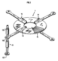
- the plates (7), (6), (5), (4) may be equipped (see FIG. 2) with at least one deflector.
- deflectors When several deflectors are used, these can be identical or different, flexible or hard (such as (14), (15), (16) in FIG. 2, the use of which is to promote dispersion and the projection of the grains).
- FIG. 2 represents a plate, here plate 7, in perspective.
- These deflectors will have varied shapes suitable for the shape of the powder particles.
- the radii of the trays can be adjustable, that is to say increased or decreased to create or to increase the width of the ring of solids projected at the bottom of the container (for example crowns E1, E2, E3 and E4 in FIG. 4 ). There are thus easily adaptable or modifiable trays for preliminary filling tests.
- FIG. 3 illustrates a tray in the following 4 cases: deflector (18) of Figure 2.
- deflector (16) of Figure 2 tray with straight or curved ridges, tray with corrugated surface (for better attachment of solids.
- the lower plate ((4) in Figures 1 and 4) can be fitted with a self-regulating flow system (with automatic opening) adapting to the rotation or filling speed (weights (13) in Figure 1 ).
- the same principle can equip the other platforms.
- the speed of rotation of a plate can vary between 15 and 780 revolutions per minute.
- FIG. 4 also illustrates the invention.
- a container (100) which is to be filled with pulverulent solids using the apparatus according to the invention.
- the pipe (101) allows granular solids to be introduced into the apparatus according to the invention.
- the neck (103) (or reactor flange) makes it possible to fix the apparatus according to the invention in the upper part of the enclosure (100).
- a grid (104) can facilitate the flow of solids towards the apparatus according to the invention.
- This figure 4 clearly shows that each tray (or stage) sprinkles its own crown at the bottom of the container, which gradually fills homogeneously.
- the invention is particularly suitable for supplying catalyst to reforming reactors, for producing aromatic hydrocarbons from various feeds, for example C2-C3, C2-C5, C2-C7, C5-C7, C2-C10 etc. with reforming type catalysts or with catalysts based on zeolites of MFI type containing or not various promoters, such as for example gallium.
- FIG. 5 illustrates the apparatus, when the embodiment of the apparatus corresponds to a spiral shape.
- Each plate 4, 5, 6, 7, (powered by a motor (2)) has a spiral shape.
- the spiral can be of continuous shape. Continuity will be from one plateau to another; as indicated above, for an intermediate plate, the shortest radius of the spiral may correspond to the longest radius of the spiral of the plate below. The longest radius corresponds to the shortest radius of the spiral of the top plate.
- the plates can be provided with strips (tubes or profiles in particular), for example flat radial strips or curved radial strips.
- FIG. 5 illustrates an exploded view of the trays.
- FIG. 6 illustrates the aerial view of the plates, thus showing the continuous appearance of a single spiral.
- the following table gives, for various pulverulent solids, on the one hand, the filling density obtained when the divided solids are poured in bulk into a container, and on the other hand when they are introduced into the container in accordance with the present invention.
Landscapes
- Chemical & Material Sciences (AREA)
- Engineering & Computer Science (AREA)
- Mechanical Engineering (AREA)
- Organic Chemistry (AREA)
- Chemical Kinetics & Catalysis (AREA)
- Devices And Processes Conducted In The Presence Of Fluids And Solid Particles (AREA)
- Basic Packing Technique (AREA)
- Filling Or Emptying Of Bunkers, Hoppers, And Tanks (AREA)
Abstract
Description
Le remplissage des récipients par des particules solides (solides granuleux) s'effectue généralement par un transvasement du solide à l'aide d'une trémie et/ou d'une manche, soit manuellement, soit mécaniquement, soit par transfert pneumatique.The filling of the containers with solid particles (granular solids) is generally carried out by transferring the solid using a hopper and / or a sleeve, either manually, mechanically or by pneumatic transfer.
En règle générale, il est d'un intérêt majeur d'introduire le maximum de produit dans un volume donné, et ceci aussi bien pour diminue le coût du stockage, que pour d'autres motifs spécifiques, comme par exemple homogénéiser ce stockage ou diminuer le volume d'air ou de gaz du conteneur. L'objet de la présente invention est de définir un appareillage qui permet de réaliser un accroissement de la quantité de solide introduite dans un certain volume.In general, it is of major interest to introduce the maximum of product in a given volume, and this as well to decrease the cost of the storage, as for other specific reasons, like for example to homogenize this storage or to decrease the volume of air or gas in the container. The object of the present invention is to define an apparatus which makes it possible to achieve an increase in the quantity of solid introduced into a certain volume.
Les stockages usuels concernent les grains de céréales (silos), de produits alimentaires destinés à la consommation ou au bétail, à l'agroalimentaire, aux engrais, aux produits chimiques, aux granulés de plastique, aux produits pharmaceutiques et/ou cosmétiques, et tout autre solide divisé (grains ou dragées, ou granulés extrudés, comprimés, agglomérés, concassés, etc). Leur autre domaine d'application est constitué par des récipients ou des réacteurs chimiques destinés à être remplis par des particules solides : catalyseurs, adsorbants, réactifs, garnissages, remplissages divers...Usual storage concerns cereal grains (silos), food products intended for consumption or livestock, food, fertilizers, chemicals, plastic pellets, pharmaceuticals and / or cosmetics, and all other divided solid (grains or dragees, or extruded granules, tablets, agglomerates, crushed, etc.). Their other field of application consists of containers or chemical reactors intended to be filled with solid particles: catalysts, adsorbents, reagents, packings, various fillings ...
Dans ce cas, il est presque toujours avantageux de placer le maximum de produit solide à l'intérieur du réacteur pour en augmenter l'activité par unité de volume et donc l'efficacité et la durée utile de service (durée de cycle ou durée de vie).In this case, it is almost always advantageous to place the maximum of solid product inside the reactor in order to increase the activity per unit of volume and therefore the efficiency and the useful service life (cycle time or duration of life).
Un procédé convenable consiste à utiliser l'appareillage décrit dans le brevet français n° 2.431.449. D'autres appareillages ont déjà été décrits dans l'art antérieur, en particulier le dispositif décrit dans de brevet DE-A-2.703.329. Le brevet DE-A-2.703.329 (voir en particulier la figure 2 dudit brevet) décrit un appareillage pour le remplissage d'un récipient par un produit divisé ou des solides divisés comportant:
- une trémie (15) munie d'un moteur (M) solidaire de la trémie,
- un arbre (10) entraîné par le moteur (M), dont l'axe est sensiblement vertical,
- une tête de dispersion mise en rotation par ledit moteur, la tête de dispersion comportant au moins trois plateaux (6, 7 et 8) sensiblement parallèles et coaxiaux, et sensiblement circulaires, disposés les uns au dessous des autres et dont le rayon va en diminuant depuis de plateau supérieur (8) jusqu'au plateau inférieur (6), chaque plateau (à l'exception du plateau inférieur (6)) étant évidé par une forme d'espace annulaire, dans lequel les solides divisés s'écoulent par gravité, les espaces annulaires étant concentriques, le diamètre de chaque espace annulaire allant en diminuant depuis l'espace annulaire associé au plateau supérieur (8) jusqu'à l'espace annulaire immédiatement au-dessus du plateau inférieur, une partie des solides divisés s'écoulant de chaque annulaire dans l'espace annulaire concentrique immédiatement en-dessous, une autre partie des solides s'écoulant de chaque espace annulaire sur le plateau (6-7) au-dessus duquel il débouche, les solides divisés qui tombent sur ce plateau (6-8) étant soumis à un mouvement rotatif dû à la rotation du plateau (6-8) sur lequel ils sont tombés, la force centrifuge engendrée par la rotation des plateaux (6-8) à partir duquel les solides sont éjectés dans l'enceinte à remplir. Mais l'appareil de la présente invention présente d'autres avantages, et notamment des avantages particuliers que l'on comprendra mieux dans la description qui suit.
- a hopper (15) fitted with a motor (M) integral with the hopper,
- a shaft (10) driven by the motor (M), whose axis is substantially vertical,
- a dispersion head rotated by said motor, the dispersion head comprising at least three plates (6, 7 and 8) substantially parallel and coaxial, and substantially circular, arranged one below the other and whose radius is decreasing from the upper plate (8) to the lower plate (6), each plate (with the exception of the lower plate (6)) being hollowed out by a form of annular space, in which the divided solids flow by gravity , the annular spaces being concentric, the diameter of each annular space decreasing from the annular space associated with the upper plate (8) to the annular space immediately above the lower plate, part of the divided solids s' flowing from each annular in the concentric annular space immediately below, another part of the solids flowing from each annular space on the plate (6-7) above which it opens, solid them es divided which fall on this plate (6-8) being subjected to a rotary movement due to the rotation of the plate (6-8) on which they fell, the centrifugal force generated by the rotation of the plates (6-8) to from which the solids are ejected into the enclosure to be filled. However, the apparatus of the present invention has other advantages, and in particular particular advantages which will be better understood in the description which follows.
La figure 1 illustre l'invention. L'appareil est constitué d'une trémie d'alimentation fixe (1) renfermant de préférence en son centre un moteur (2) par exemple pneumatique, alimenté éventuellement par un gaz (de l'air par exemple). Ce moteur est solidaire de la trémie. Le moteur (2) entraîne un arbre (3) qui met en rotation une tête de dispersion à laquelle cet arbre est fixé. Cette tête de dispersion comporte au moins deux plateaux, de préférence au moins trois ou quatre plateaux. Sur la figure 1, on a représenté quatre plateaux (4), (5), (6) et (7), généralement solidaires entre eux, par exemple par l'intermédiaire d'un support, par exemple la tige (19) sur la figure 1.Figure 1 illustrates the invention. The device consists of a fixed feed hopper (1) preferably containing in its center a motor (2), for example pneumatic, possibly supplied by a gas (air for example). This engine is integral with the hopper. The motor (2) drives a shaft (3) which rotates a dispersion head to which this shaft is fixed. This dispersing head comprises at least two plates, preferably at least three or four plates. In Figure 1, there are shown four plates (4), (5), (6) and (7), generally integral with each other, for example by means of a support, for example the rod (19) on Figure 1.
Les solides pulvérulents s'écoulent par gravité de haut en bas à travers une série de tubes (au moins deux tubes, et de préférence au moins 3 ou 4) concentriques et dont de diamètre diminue de haut en bas. Ainsi les solides s'écoulent d'abord dans le tube (9) puis dans des tubes concentriques coaxiaux (10), (11) et (12) de diamètre de plus en plus petit. Ces tubes peuvent être démontables et coulissants si nécessaires, et sont caractéristiques de la présente invention.The pulverulent solids flow by gravity from top to bottom through a series of tubes (at least two tubes, and preferably at least 3 or 4) concentric and whose diameter decreases from top to bottom. Thus the solids flow first in the tube (9) then in concentric coaxial tubes (10), (11) and (12) of increasingly smaller diameter. These tubes can be removable and sliding if necessary, and are characteristic of the present invention.
A chaque changement de tube, une partie au moins des solides granuleux tombent sur un des plateaux (7), (6), (5) et (4). Le plateau (7) tourne autour du tube (10) et il est alimenté par le tube de descente (9), fixe de préférence et relié lui-même au palier (8). Les autres tubes de descente des solides (10), (11) et (12), fixes ou mûs d'un faible mouvement de rotation de préférence, et de diamètre de plus en plus petit, créent des espaces annulaires concentriques permettant aux grains ou aux solides granuleux d'alimenter respectivement les plateaux (6), (5) et (4). Les plateaux (6) et (5) tournent respectivement autour des tubes (10), (11) et (12). Le plateau (4) tourne autour de l'arbre (3). Sous l'effet de la force centrifuge, les particules solides sont projetées dans le volume à remplir. Les plateaux (7), (6), (5), (4) pourront être équipés (voir figure 2) d'au moins un déflecteur. Lorsqu'on utilise plusieurs déflecteurs, ceux-ci peuvent être identiques ou différents, souples ou durs (tels(s) que (14), (15), (16) sur la figure 2, dont l'usage est de favoriser la dispersion et la projection des grains). La figure 2 représente un plateau, ici le plateau 7, en perspective. Ces déflecteurs auront des formes variées et adéquates à la forme des particules pulvérulentes. Les rayons des plateaux pourront être réglables, c'est-à-dire augmentés ou diminués pour créer ou pour augmenter la largeur de la couronne de solides projetée au fond du récipient (par exemple couronnes E1, E2, E3 et E4 sur la figure 4). On dispose ainsi de plateaux facilement adaptables ou modifiables pour des essais préliminaires de remplissage. Les plateaux peuvent avoir une surface continue ou discontinue. La figure 3 illustre un plateau sur les 4 cas suivants : déflecteur (18) de la figure 2. déflecteur (16) de la figure 2, plateau avec stries droites ou courbes, plateau à surface ondulée (pour un meilleur accrochage des solides.At each tube change, at least part of the granular solids fall on one of the plates (7), (6), (5) and (4). The plate (7) rotates around the tube (10) and it is supplied by the downpipe (9), preferably fixed and itself connected to the bearing (8). The other solid downpipes (10), (11) and (12), fixed or moved with preferably a small rotational movement, and of increasingly smaller diameter, create concentric annular spaces allowing the grains or granular solids to feed the plates (6), (5) and (4) respectively. The plates (6) and (5) rotate respectively around the tubes (10), (11) and (12). The plate (4) rotates around the shaft (3). Under the effect of centrifugal force, the solid particles are projected into the volume to be filled. The plates (7), (6), (5), (4) may be equipped (see FIG. 2) with at least one deflector. When several deflectors are used, these can be identical or different, flexible or hard (such as (14), (15), (16) in FIG. 2, the use of which is to promote dispersion and the projection of the grains). FIG. 2 represents a plate, here
Le plateau inférieur ((4) sur les figures 1 et 4) pourra être équipé d'un système auto régulant de débit (avec ouverture automatique) s'adaptant à la vitesse de rotation ou de remplissage (masselottes (13) sur la figure 1). Le même principe pourra équiper les autres plateaux.The lower plate ((4) in Figures 1 and 4) can be fitted with a self-regulating flow system (with automatic opening) adapting to the rotation or filling speed (weights (13) in Figure 1 ). The same principle can equip the other platforms.
En bref, l'invention concerne un appareillage pour le remplissage d'un récipient par un produit divisé ou des solides divisés comportant (voir figure 1):
- une trémie (1) munie d'un moteur (2) solidaire de la trémie.
- un arbre (3) sensiblement vertical entraîné par le moteur,
- une tête de dispersion mise en rotation par le dit moteur, la tête de dispersion comportant au moins deux plateaux, de préférence au moins 3 ou 4 (tels que (7), (6), (5) et (4)) sensiblement parallèles et coaxiaux, et sensiblement circulaires, disposés les uns au dessous des autres et dont le rayon va en diminuant depuis le plateau supérieur jusqu'au plateau inférieur,
- une série d'au moins trois tubes, de préférence au moins 4, tels que (9), (10), (11) et (12) sensiblement en forme de cylindres concentriques, empilés et coaxiaux éventuellement démontables et coulissants, dans lesquels les solides divisés s'écoulent par gravité, chaque cylindre ayant son extrémité inférieure au dessus d'un plateau, chaque cylindre sauf le le plus haut ayant son extrémité supérieure sensiblement au niveau de l'extrémité inférieure du cylindre situé au dessus, le diamètre de chaque tube étant inférieur au diamètre du tube qui le surmonte et supérieur au diamètre du tube qu'il surmonte, chaque plateau étant ainsi associé à un tube autour duquel il tourne, le plateau inférieur tournant autour de l'arbre (3), une partie des solides divisés s'écoulant de chaque tube dans le tube immédiatement en dessous, une autre partie des solides s'écoulant de chaque tube sur le plateau au dessus duquel il débouche, les solides divisés qui tombent sur ce plateau étant soumis à un mouvement rotatif dû à la rotation du plateau sur lequel ils sont tombés, la force centrifuge engendrée par la rotation des plateaux permettant d'éjecter les solides à des distances différentes de l'axe de l'arbre, sensiblement proportionnelles au rayon du plateau à partir duquel les solides ont été projetés dans l'enceinte à remplir.
- a hopper (1) provided with a motor (2) integral with the hopper.
- a substantially vertical shaft (3) driven by the motor,
- a dispersion head rotated by said motor, the dispersion head comprising at least two plates, preferably at least 3 or 4 (such as (7), (6), (5) and (4)) substantially parallel and coaxial, and substantially circular, arranged one below the other and whose radius decreases from the upper plate to the lower plate,
- a series of at least three tubes, preferably at least 4, such as (9), (10), (11) and (12) substantially in the form of concentric cylinders, stacked and coaxial, possibly removable and sliding, in which the divided solids flow by gravity, each cylinder having its lower end above a tray, each cylinder except the highest having its upper end substantially at the level of the lower end of the cylinder located above, the diameter of each tube being less than the diameter of the tube which overcomes it and greater than the diameter of the tube which it surmounts, each plate thus being associated with a tube around which it rotates, the lower plate rotating around the shaft (3), part of the divided solids flowing from each tube into the tube immediately below, another part of the solids flowing from each tube onto the tray above which it opens, the divided solids falling on it e plate being subjected to a rotary movement due to the rotation of the plate on which they fell, the centrifugal force generated by the rotation of the plates making it possible to eject the solids at different distances from the axis of the shaft, substantially proportional the radius of the tray from which the solids have been projected into the enclosure to be filled.
A noter que sur la figure 2, on a également représenté pour le plateau (7) la tige (19) solidaire du plateau 7 et comportant notamment une entretoise (105), une une filetée (106) et le support (107) pour le repos de l'appareil au sol.Note that in Figure 2, there is also shown for the plate (7) the rod (19) integral with the
A titre indicatif, la vitesse de rotation d'un plateau peut varier entre 15 et 780 tours par minute.As an indication, the speed of rotation of a plate can vary between 15 and 780 revolutions per minute.
La figure 4 illustre également l'invention. On a représenté un récipient (100) que l'on veut remplir de solides pulvérulents à l'aide de l'appareillage selon l'invention. La conduite (101) permet d'introduire les solides granuleux dans l'appareillage selon l'invention. Le goulot (103) (ou bride de réacteur) permet de fixer l'appareillage selon l'invention dans la partie supérieure de l'enceinte (100). Généralement, une grille (104) peut faciliter l'écoulement des solides vers l'appareillage selon l'invention. Cette figure 4 montre clairement que chaque plateau (ou étage) arrose sa propre couronne au fond du récipient, lequel se remplit ainsi peu à peu de façon homogène.Figure 4 also illustrates the invention. There is shown a container (100) which is to be filled with pulverulent solids using the apparatus according to the invention. The pipe (101) allows granular solids to be introduced into the apparatus according to the invention. The neck (103) (or reactor flange) makes it possible to fix the apparatus according to the invention in the upper part of the enclosure (100). Generally, a grid (104) can facilitate the flow of solids towards the apparatus according to the invention. This figure 4 clearly shows that each tray (or stage) sprinkles its own crown at the bottom of the container, which gradually fills homogeneously.
Les avantages d'un tel système sont essentiellement les suivants :
- compacité,
- simplicité,
- sécurité intrinsèque (l'arrêt du fluide pneumatique stoppe la rotation des plateaux, donc l'écoulement),
- ventilation du milieu par la forme des plateaux déflecteurs et élimination des fines,
- homogénéité du remplissage et gain de volume élevé,
- grande plage de débits possible pour un même appareil grâce à la flexibilité ∅ trémie et ∅ plateau,
- contrôle aisé de la vitesse de rotation,
- contrôle du débit indépendant de la vitesse de rotation,
- variation du débit en continu.
- compactness,
- simplicity,
- intrinsic safety (stopping the pneumatic fluid stops the rotation of the plates, therefore the flow),
- ventilation of the medium by the shape of the deflector plates and elimination of fines,
- homogeneity of filling and high volume gain,
- large flow range possible for the same device thanks to the flexibility ∅ hopper and ∅ plate,
- easy control of the rotation speed,
- flow control independent of the rotation speed,
- continuous flow variation.
La conception du système permet d'accepter le chargement de solides divisés de densité élevée (tels que catalyseurs lourds de densité comprise entre 2 et 4. De plus le chargement de catalyseurs poussiéreux se fait sans présence humaine à l'intérieur du réacteur.The design of the system makes it possible to accept the loading of divided solids of high density (such as heavy catalysts of density between 2 and 4. In addition, the loading of dusty catalysts is done without human presence inside the reactor.
On réalise ainsi des gains de remplissage de l'ordre de 10 à 35 % par rapport aux systèmes de l'art antérieur.This achieves filling gains of the order of 10 to 35% compared to the systems of the prior art.
L'invention convient particulièrement bien pour alimenter en catalyseur les réacteurs de reformage, de production d'hydrocarbures aromatiques à partir de diverses charges par exemple C₂-C₃, C₂-C₅, C₂-C₇, C₅-C₇, C₂-C₁₀ etc... avec des catalyseurs de type reformage ou avec des catalyseurs à base de zéolites de type MFI contenant ou non divers promoteurs, tels que par exemple le gallium.The invention is particularly suitable for supplying catalyst to reforming reactors, for producing aromatic hydrocarbons from various feeds, for example C₂-C₃, C₂-C₅, C₂-C₇, C₅-C₇, C₂-C₁₀ etc. with reforming type catalysts or with catalysts based on zeolites of MFI type containing or not various promoters, such as for example gallium.
Dans la présente invention, on a également découvert que la répartition du catalyseur dans le récipient était plus régulière en utilisant, dans l'appareillage de la demande principale, au moins trois plateaux de forme elliptique.In the present invention, it has also been found that the distribution of the catalyst in the container is more regular by using, in the apparatus of the main application, at least three trays of elliptical shape.
La figure 5 illustre l'appareillage, lorsque le mode de réalisation de l'appareillage correspond à une forme spiralée.
Chaque plateau 4, 5, 6, 7, (alimenté par un moteur (2)) a une forme de spirale. La spirale peut être de forme continue. La continuité se fera d'un plateau à un autre ; ainsi qu'indiqué plus haut, pour un plateau intermédiaire, le rayon le plus court de la spirale pourra correspondre au rayon le plus long de la spirale du plateau du dessous. Le rayon le plus long correspond au rayon le plus court de la spirale du plateau du dessus.FIG. 5 illustrates the apparatus, when the embodiment of the apparatus corresponds to a spiral shape.
Each
Les plateaux pourront être pourvus de lamelles, (tubes ou profilés notamment) par exemple des lamelles radiales plates ou des lamelles radiales incurvées.The plates can be provided with strips (tubes or profiles in particular), for example flat radial strips or curved radial strips.
La figure 5 illustre une vue éclatée des plateaux. La figure 6 illustre la vue aérienne des plateaux, montrant ainsi l'aspect continu d'une spirale unique.Figure 5 illustrates an exploded view of the trays. FIG. 6 illustrates the aerial view of the plates, thus showing the continuous appearance of a single spiral.
Le tableau suivant donne pour divers solides pulvérulents d'une part la densité de remplissage obtenue lorsque les solides divisés sont versés en vrac dans un récipient, et d'autre part lorsqu'ils sont introduits dans le récipient conformément à la présente invention.

Il en découle une réduction de la fraction du volume intergranulaire de 20 à 50 %, donc à l'augmentation de la capacité de stockage, vient s'ajouter une diminution du volume de gaz contenu dans de milieu, et s'il y a lieu une réduction de la consommation de gaz nécessaireà inerter le milieu.This results in a reduction in the fraction of the intergranular volume of 20 to 50%, therefore to the increase in storage capacity, is added a decrease in the volume of gas contained in medium, and if necessary a reduction in the consumption of gas necessary to inert the environment.
Claims (9)
- An apparatus for filling a receptacle with a divided product or divided solids and comprising- a hopper (1) fitted with a motor (2) rigid with the hopper,- a substantially vertical shaft (3) driven by the motor,- a dispersion head which is caused to rotate by the said motor, the dispersion head comprising at least three plates (such as (7), (6), (5) and (4)) which are substantially parallel and coaxial and substantially in one of the following shapes: circular, elliptical, spiral, disposed beneath one another and the radius of which decreases from the top plate to the bottom plate,- a series of at least three tubes(such as (9), (10), (11) and (12)) of substantially concentric cylindrical form, stacked and coaxial, adapted for sliding movement, in which the divided solids flow by gravity, each cylinder having its bottom end above a plate, each cylinder except the highest having its upper end substantially at the level of the bottom end of the cylinder situated above, the diameter of each tube with the exception of the top tube being less than the diameter of the tube which surmounts it and, with the exception of the bottom tube, greater than the diameter of the tube which it surmounts, each plate, with the exception of the bottom plate, being thus associated with a tube about which it rotates, the radius of the tube being less than the smallest distance between the outer edge of the plate and the axis about which the said plate rotates, the bottom plate turning about the shaft (3), a part of the divided solids flowing from each tube, with the exception of the bottom tube, into the tube immediately underneath, another part of the solids flowing from each tube onto the plate on top of which it discharges, the divided solids which fall onto this plate being subjected to a rotary movement due to the rotation of the plate onto which they have fallen, the centrifugal force generated by the rotation of the plates making it possible to eject the solids at different distances from the axis of the shaft, substantially proportional to the radius of the plate from which the solids have been projected into the enclosure to be filled.
- An apparatus according to Claim 1 in which the concentric tubes cannot enjoy a relative rotary movement in respect of the dispersion head and about the vertical axis.
- An apparatus according to Claim 1 in which the concentric tubes may enjoy a relative rotary movement about the same vertical axis and in relation to the dispersion head.
- An apparatus according to one of Claims 1 and 3 in which at least one plate is fitted with at least one deflector.
- An apparatus according to Claim 4 in which it is possible to vary the length of the radius of at least one plate.
- An apparatus according to one of Claims 1 to 5 in which the bottom plate is equipped with an automatic flow-regulating system for adaptation to the speed of rotation or filling.
- An apparatus according to one of Claims 1 to 6 in which each of the plates is equipped with the same auto-regulating system.
- An apparatus according to Claim 7 in which the said auto-regulating system is composed of feed heads.
- An apparatus according to one of Claims 1 to 8, comprising more particularly at least three plates (such as (7), (6), (5) and (4) (see Fig. 5)) substantially parallel and coaxial and substantially elliptical, disposed one beneath the other and of which the radius decreases from the top plate down to the bottom plate.
Priority Applications (1)
| Application Number | Priority Date | Filing Date | Title |
|---|---|---|---|
| AT90907099T ATE91269T1 (en) | 1989-04-27 | 1990-04-19 | DEVICE FOR FILLING A CONTAINER WITH BULK MATERIAL. |
Applications Claiming Priority (6)
| Application Number | Priority Date | Filing Date | Title |
|---|---|---|---|
| FR8905780 | 1989-04-27 | ||
| FR8905780A FR2646399B1 (en) | 1989-04-27 | 1989-04-27 | APPARATUS FOR FILLING A CONTAINER WITH A DIVIDED SOLID PRODUCT |
| FR8910287 | 1989-07-27 | ||
| FR8910287A FR2650250B2 (en) | 1989-04-27 | 1989-07-27 | APPARATUS FOR FILLING A CONTAINER |
| FR8913469 | 1989-10-12 | ||
| FR8913469A FR2653092B2 (en) | 1989-04-27 | 1989-10-12 | APPARATUS FOR FILLING A CONTAINER WITH PARTICLES OF DIVIDED SOLIDS. |
Publications (2)
| Publication Number | Publication Date |
|---|---|
| EP0470142A1 EP0470142A1 (en) | 1992-02-12 |
| EP0470142B1 true EP0470142B1 (en) | 1993-07-07 |
Family
ID=27251880
Family Applications (1)
| Application Number | Title | Priority Date | Filing Date |
|---|---|---|---|
| EP90907099A Expired - Lifetime EP0470142B1 (en) | 1989-04-27 | 1990-04-19 | Equipment for filling a container with a divided solid product |
Country Status (5)
| Country | Link |
|---|---|
| US (1) | US5238035A (en) |
| EP (1) | EP0470142B1 (en) |
| CA (1) | CA2051661C (en) |
| ES (1) | ES2044586T3 (en) |
| WO (1) | WO1990012746A1 (en) |
Families Citing this family (25)
| Publication number | Priority date | Publication date | Assignee | Title |
|---|---|---|---|---|
| US5348434A (en) * | 1992-10-21 | 1994-09-20 | East Coast Terminal Assoc., Ltd. | Cargo loading system |
| US5421379A (en) * | 1993-09-24 | 1995-06-06 | Ctb Inc. | Method and apparatus for distributing granular material within a container |
| US5906293A (en) * | 1993-09-24 | 1999-05-25 | Ctb, Inc. | Method and apparatus for maintaining uniform mass flow of granular material out of a container |
| FR2721900B1 (en) * | 1994-06-30 | 1996-08-23 | Inst Francais Du Petrole | APPARATUS FOR FILLING A CONTAINER WITH SPHERICAL PARTICLES |
| US5746258A (en) * | 1996-04-03 | 1998-05-05 | Waeschle Inc. | Apparatus for filling a container with free-flowing bulk material |
| US5836362A (en) * | 1997-07-15 | 1998-11-17 | Praxair Technology, Inc. | Multiple adsorbent loading method and apparatus for a radial flow vessel |
| IT1299513B1 (en) * | 1998-06-12 | 2000-03-16 | Autostrade Concess Const | MODULAR SILO FOR STORAGE OF SOLID CHLORIDES AND IN SOLUTION, EQUIPPED WITH AN ADDRESSABLE JET DISTRIBUTING DISC SYSTEM |
| FR2812824B1 (en) * | 2000-08-10 | 2003-05-30 | Total Raffinage Distribution | NEW PROCESS FOR HOMOGENEOUS LOADING OF SOLID PARTICLES INTO AN ENCLOSURE |
| US6571990B2 (en) | 2001-03-30 | 2003-06-03 | Ctb Ip, Inc. | Method and apparatus for adjustably directing granular material out of a container and reducing outlet pressure in the container |
| NO317083B1 (en) * | 2002-09-27 | 2004-08-02 | Catalyst Services Inc | Method of loading particulate matter into vertical rudders |
| US6729365B1 (en) | 2003-03-28 | 2004-05-04 | Laval Cote | Distribution device for use with a silo |
| FR2862625B1 (en) | 2003-11-25 | 2006-02-10 | Bernard Poussin | APPARATUS FOR FILLING A CONTAINER WITH SOLID PARTICLES |
| US7427182B2 (en) * | 2004-12-01 | 2008-09-23 | Intray Consolidated Pty Ltd | Agitator loading system |
| CA2602955C (en) | 2005-03-25 | 2013-07-02 | Catalyst Services, Inc. | Filling tubes with catalyst and/or other particulate |
| US20080086932A1 (en) * | 2006-10-13 | 2008-04-17 | Cook Peter J | Insect-attraction apparatus |
| US8123452B2 (en) * | 2006-10-31 | 2012-02-28 | Sukup Manufacturing Co. | Pre-spread device for grain spreader |
| US7987879B2 (en) * | 2007-03-07 | 2011-08-02 | Cat Tech, Inc. | Methods and apparatus for dense particle loading |
| US8025472B2 (en) * | 2007-06-01 | 2011-09-27 | Catalyst Services, Inc. | Catalyst loading system |
| FR2940641B1 (en) * | 2008-12-31 | 2013-02-01 | Total Raffinage Marketing | DEVICE FOR LOADING SOLID PARTICLES IN AN ENCLOSURE |
| FR2954302B1 (en) * | 2009-12-21 | 2012-05-25 | Total Raffinage Marketing | DEVICE FOR LOADING SOLID PARTICLES IN AN ENCLOSURE |
| FR2969587B1 (en) * | 2010-12-27 | 2013-01-04 | Total Raffinage Marketing | ALLOY DEVICE FOR LOADING SOLID PARTICLES |
| DE102011054086B4 (en) * | 2011-09-30 | 2013-05-23 | Thyssenkrupp Polysius Ag | Roller mill and method for comminuting brittle regrind |
| AT511804B1 (en) * | 2011-11-17 | 2013-03-15 | Berndorf Band Gmbh | DEVICE FOR PRODUCING A PLATE OF PLASTIC MATERIAL |
| EP3288675B1 (en) | 2015-04-29 | 2024-08-14 | CLPros, LLC | Loading vertical tubes with particulate material |
| EP3909867B1 (en) * | 2020-05-15 | 2023-08-30 | Tetra Laval Holdings & Finance S.A. | A method and a device for filling powder material in a bag |
Family Cites Families (26)
| Publication number | Priority date | Publication date | Assignee | Title |
|---|---|---|---|---|
| US1560800A (en) * | 1922-09-13 | 1925-11-10 | Edward Mckain | Feeding and distributing apparatus for roller mills |
| FR1438867A (en) * | 1964-07-03 | 1966-05-13 | Alfa Laval Ab | Apparatus for distributing materials into storage containers, such as silos |
| US3428156A (en) * | 1967-01-23 | 1969-02-18 | Kaiser Ind Corp | Expandable chute device |
| NL161033C (en) * | 1967-12-27 | 1980-01-15 | Lely Nv C Van Der | DEVICE FOR DISTRIBUTION OF MATERIAL. |
| US3469718A (en) * | 1968-02-01 | 1969-09-30 | Grove Mfg Co | Spreader for grain bins |
| US3599878A (en) * | 1969-06-10 | 1971-08-17 | Dale Corp Van | Distributor apparatus |
| US3626964A (en) * | 1970-09-03 | 1971-12-14 | Wheelabrator Corp | Regulating valve for magnetic materials |
| US3966124A (en) * | 1974-03-20 | 1976-06-29 | Sukup Eugene G | Spreader for grain and like material |
| US4135560A (en) * | 1976-12-20 | 1979-01-23 | Union Carbide Corporation | Apparatus for filling bulk material containers |
| DE2703329C3 (en) * | 1977-01-27 | 1981-04-16 | Gebrüder Weiss KG, 6340 Dillenburg | Arrangement for level filling of vertical containers |
| GB2014189B (en) * | 1977-12-21 | 1982-06-09 | Bristol Aerojet Ltd | Processes for the electrodeposition of composite coatings |
| US4300725A (en) * | 1979-09-13 | 1981-11-17 | Moherek Edward F | Apparatus for uniformly dispensing and distributing material |
| SU1005696A1 (en) * | 1981-04-02 | 1983-03-23 | Bersenev Aleksandr | Mineral fertilizer spreader |
| BE899420A (en) * | 1984-04-13 | 1984-07-31 | Transtec Operating Ltd Company | Material delivery feed for silo - has curved projector blades at outlet to vary distribution of feed |
| IN166220B (en) * | 1984-12-07 | 1990-03-31 | Chevron Res | |
| US4972884A (en) * | 1984-12-07 | 1990-11-27 | Chevron Research & Technology Company | Method and apparatus for uniformly loading particulate material into cylindrical beds |
| US4727913A (en) * | 1986-03-03 | 1988-03-01 | Occidental Chemical Corporation | Dust control loading device |
| DE3855726D1 (en) * | 1987-03-06 | 1997-02-06 | Amazonen Werke Dreyer H | Centrifugal fertilizer spreader |
| DE8717739U1 (en) * | 1987-03-17 | 1989-11-16 | Agrichema Materialflußtechnik GmbH, 55257 Budenheim | Loading device for loose loading of dusty bulk goods |
| SU1495206A1 (en) * | 1987-06-26 | 1989-07-23 | Институт Горного Дела Со Ан Ссср | Device for metering powder materials |
| DK168185B1 (en) * | 1988-02-15 | 1994-02-28 | Laursen As A P | Centrifugal spreader type machine for spraying grain and powdered material |
| US4857205A (en) * | 1988-02-22 | 1989-08-15 | Petrolite Corporation | Method for inhibition of scale formation |
| US4821861A (en) * | 1988-05-31 | 1989-04-18 | Robert Shanahan | Bulk material chute system |
| GB8814275D0 (en) * | 1988-06-16 | 1988-07-20 | Dow Chemical Gmbh | Process for preparing aminomethylphosphonic chelating agent |
| DE59004766D1 (en) * | 1989-11-03 | 1994-04-07 | Amazonen Werke Dreyer H | Centrifugal fertilizer spreader. |
| CA2433802A1 (en) * | 2001-01-16 | 2002-07-25 | Incyte Genomics, Inc. | Secretory molecules |
-
1990
- 1990-04-19 ES ES90907099T patent/ES2044586T3/en not_active Expired - Lifetime
- 1990-04-19 US US07/781,166 patent/US5238035A/en not_active Expired - Lifetime
- 1990-04-19 WO PCT/FR1990/000284 patent/WO1990012746A1/en not_active Ceased
- 1990-04-19 EP EP90907099A patent/EP0470142B1/en not_active Expired - Lifetime
- 1990-04-19 CA CA002051661A patent/CA2051661C/en not_active Expired - Lifetime
Also Published As
| Publication number | Publication date |
|---|---|
| ES2044586T3 (en) | 1994-01-01 |
| CA2051661C (en) | 2000-02-29 |
| CA2051661A1 (en) | 1990-10-28 |
| US5238035A (en) | 1993-08-24 |
| WO1990012746A1 (en) | 1990-11-01 |
| EP0470142A1 (en) | 1992-02-12 |
Similar Documents
| Publication | Publication Date | Title |
|---|---|---|
| CA2051661C (en) | Apparatus for filling a container with divided solid product | |
| FR2668131A1 (en) | APPARATUS FOR FILLING A CONTAINER WITH A DIVIDED SOLID PRODUCT | |
| EP0007854B1 (en) | Device for the distribution of bulk material in an enclosure | |
| EP0116246B1 (en) | Container filling device with solid particulate matter | |
| JP3524388B2 (en) | Method and apparatus for multiple loading of adsorbent for radial flow vessels | |
| BE1004913A3 (en) | POWDER DISPENSING APPARATUS AND RELATED METHOD. | |
| EP2475602A1 (en) | Device for densely loading a divided solid into a chamber | |
| EP0769462B1 (en) | Method and device to distribute uniformly a solid in a finely divided form in a vessel | |
| EP1556671A1 (en) | Apparatus for accurate powder metering | |
| FR2598332A1 (en) | Process and device for bringing materials into contact by fluidising | |
| EP1687223B1 (en) | Apparatus for filling a container with solid particles | |
| US3804273A (en) | Catalyst distribution apparatus | |
| FR2646399A1 (en) | Apparatus for filling a container with a divided solid product | |
| FR2588783A1 (en) | METHOD AND APPARATUS FOR REALIZING THE SEPARATION OF SPHERICAL MATERIALS WITH OR WITHOUT IMPERFECTIONS | |
| FR2721900A1 (en) | Device for filling container with spherical particles | |
| EP3817848A1 (en) | Filling system for a container for solid particles | |
| US20040042942A1 (en) | Continually stirred reactor system | |
| BE844749A (en) | APPARATUS FOR UNIFORMLY DISTRIBUTING A PARTICULATE MATERIAL | |
| FR2874335A1 (en) | METHOD FOR FILLING AN ENCLOSURE WITH A BED OF PARTICLES WITH VARIABLE DENSITY | |
| NL8700290A (en) | ROTATING SCREENING DEVICE WITH A NUMBER OF SCREEN SURFACES, EACH OF WHICH ARE DIVIDED INTO A NUMBER OF CONCENTRIC RINGS WITH REVERSIBLE, CONTINUOUSLY ANGLE SPEED. | |
| FR2690676A1 (en) | Enclosure filler for granular materials - comprises rotating narrowed tube connected to conveying tube end and deviating from rotation axis | |
| FR3096357A1 (en) | Advanced filling system |
Legal Events
| Date | Code | Title | Description |
|---|---|---|---|
| PUAI | Public reference made under article 153(3) epc to a published international application that has entered the european phase |
Free format text: ORIGINAL CODE: 0009012 |
|
| 17P | Request for examination filed |
Effective date: 19910923 |
|
| AK | Designated contracting states |
Kind code of ref document: A1 Designated state(s): AT BE DE ES GB IT NL SE |
|
| 17Q | First examination report despatched |
Effective date: 19920409 |
|
| ITF | It: translation for a ep patent filed | ||
| GRAA | (expected) grant |
Free format text: ORIGINAL CODE: 0009210 |
|
| AK | Designated contracting states |
Kind code of ref document: B1 Designated state(s): AT BE DE ES GB IT NL SE |
|
| REF | Corresponds to: |
Ref document number: 91269 Country of ref document: AT Date of ref document: 19930715 Kind code of ref document: T |
|
| REF | Corresponds to: |
Ref document number: 69002161 Country of ref document: DE Date of ref document: 19930812 |
|
| GBT | Gb: translation of ep patent filed (gb section 77(6)(a)/1977) |
Effective date: 19930803 |
|
| REG | Reference to a national code |
Ref country code: ES Ref legal event code: FG2A Ref document number: 2044586 Country of ref document: ES Kind code of ref document: T3 |
|
| PLBE | No opposition filed within time limit |
Free format text: ORIGINAL CODE: 0009261 |
|
| STAA | Information on the status of an ep patent application or granted ep patent |
Free format text: STATUS: NO OPPOSITION FILED WITHIN TIME LIMIT |
|
| 26N | No opposition filed | ||
| EAL | Se: european patent in force in sweden |
Ref document number: 90907099.7 |
|
| REG | Reference to a national code |
Ref country code: GB Ref legal event code: IF02 |
|
| PGFP | Annual fee paid to national office [announced via postgrant information from national office to epo] |
Ref country code: ES Payment date: 20090415 Year of fee payment: 20 |
|
| PGFP | Annual fee paid to national office [announced via postgrant information from national office to epo] |
Ref country code: AT Payment date: 20090424 Year of fee payment: 20 Ref country code: IT Payment date: 20090421 Year of fee payment: 20 Ref country code: NL Payment date: 20090427 Year of fee payment: 20 Ref country code: DE Payment date: 20090423 Year of fee payment: 20 Ref country code: SE Payment date: 20090422 Year of fee payment: 20 |
|
| PGFP | Annual fee paid to national office [announced via postgrant information from national office to epo] |
Ref country code: BE Payment date: 20090428 Year of fee payment: 20 |
|
| PGFP | Annual fee paid to national office [announced via postgrant information from national office to epo] |
Ref country code: GB Payment date: 20090424 Year of fee payment: 20 |
|
| REG | Reference to a national code |
Ref country code: NL Ref legal event code: V4 Effective date: 20100419 |
|
| BE20 | Be: patent expired |
Owner name: INSTITUT FRANCAIS DU *PETROLE Effective date: 20100419 |
|
| REG | Reference to a national code |
Ref country code: GB Ref legal event code: PE20 Expiry date: 20100418 |
|
| EUG | Se: european patent has lapsed | ||
| REG | Reference to a national code |
Ref country code: ES Ref legal event code: FD2A Effective date: 20100420 |
|
| PG25 | Lapsed in a contracting state [announced via postgrant information from national office to epo] |
Ref country code: NL Free format text: LAPSE BECAUSE OF EXPIRATION OF PROTECTION Effective date: 20100419 Ref country code: ES Free format text: LAPSE BECAUSE OF EXPIRATION OF PROTECTION Effective date: 20100420 |
|
| PG25 | Lapsed in a contracting state [announced via postgrant information from national office to epo] |
Ref country code: GB Free format text: LAPSE BECAUSE OF EXPIRATION OF PROTECTION Effective date: 20100418 |
|
| PG25 | Lapsed in a contracting state [announced via postgrant information from national office to epo] |
Ref country code: DE Free format text: LAPSE BECAUSE OF EXPIRATION OF PROTECTION Effective date: 20100419 |