EP0470253B1 - Procede d'excavation par bouclier s'opposant a la pression de la terre du front d'excavation - Google Patents
Procede d'excavation par bouclier s'opposant a la pression de la terre du front d'excavation Download PDFInfo
- Publication number
- EP0470253B1 EP0470253B1 EP90906375A EP90906375A EP0470253B1 EP 0470253 B1 EP0470253 B1 EP 0470253B1 EP 90906375 A EP90906375 A EP 90906375A EP 90906375 A EP90906375 A EP 90906375A EP 0470253 B1 EP0470253 B1 EP 0470253B1
- Authority
- EP
- European Patent Office
- Prior art keywords
- soil
- mud
- screw conveyor
- improving
- discharge screw
- Prior art date
- Legal status (The legal status is an assumption and is not a legal conclusion. Google has not performed a legal analysis and makes no representation as to the accuracy of the status listed.)
- Expired - Lifetime
Links
- 238000000034 method Methods 0.000 title claims abstract description 23
- 230000008569 process Effects 0.000 title claims abstract description 21
- 239000002689 soil Substances 0.000 claims abstract description 130
- 239000003795 chemical substances by application Substances 0.000 claims abstract description 60
- 238000009412 basement excavation Methods 0.000 claims abstract description 42
- 239000000654 additive Substances 0.000 claims abstract description 24
- 230000000996 additive effect Effects 0.000 claims abstract description 24
- XLYOFNOQVPJJNP-UHFFFAOYSA-N water Substances O XLYOFNOQVPJJNP-UHFFFAOYSA-N 0.000 claims abstract description 13
- 239000000203 mixture Substances 0.000 claims abstract description 9
- 238000007599 discharging Methods 0.000 claims abstract description 6
- 239000011248 coating agent Substances 0.000 claims 4
- 238000000576 coating method Methods 0.000 claims 4
- 230000003247 decreasing effect Effects 0.000 claims 1
- 239000012530 fluid Substances 0.000 claims 1
- 238000004880 explosion Methods 0.000 abstract description 3
- 230000001105 regulatory effect Effects 0.000 description 7
- 238000010276 construction Methods 0.000 description 4
- 238000010008 shearing Methods 0.000 description 4
- 230000006872 improvement Effects 0.000 description 3
- 239000011369 resultant mixture Substances 0.000 description 3
- 238000010586 diagram Methods 0.000 description 2
- 230000000694 effects Effects 0.000 description 2
- 230000006870 function Effects 0.000 description 2
- 230000009467 reduction Effects 0.000 description 2
- 239000002002 slurry Substances 0.000 description 2
- 239000000126 substance Substances 0.000 description 2
- 229910000278 bentonite Inorganic materials 0.000 description 1
- 239000000440 bentonite Substances 0.000 description 1
- SVPXDRXYRYOSEX-UHFFFAOYSA-N bentoquatam Chemical compound O.O=[Si]=O.O=[Al]O[Al]=O SVPXDRXYRYOSEX-UHFFFAOYSA-N 0.000 description 1
- 230000015572 biosynthetic process Effects 0.000 description 1
- 239000004927 clay Substances 0.000 description 1
- 239000000701 coagulant Substances 0.000 description 1
- 230000001276 controlling effect Effects 0.000 description 1
- 238000005520 cutting process Methods 0.000 description 1
- 238000005516 engineering process Methods 0.000 description 1
- 239000002075 main ingredient Substances 0.000 description 1
- 238000004519 manufacturing process Methods 0.000 description 1
- 238000005259 measurement Methods 0.000 description 1
- 230000003014 reinforcing effect Effects 0.000 description 1
- 238000009877 rendering Methods 0.000 description 1
- 238000007711 solidification Methods 0.000 description 1
- 230000008023 solidification Effects 0.000 description 1
- 235000013311 vegetables Nutrition 0.000 description 1
Images


Classifications
-
- E—FIXED CONSTRUCTIONS
- E21—EARTH OR ROCK DRILLING; MINING
- E21D—SHAFTS; TUNNELS; GALLERIES; LARGE UNDERGROUND CHAMBERS
- E21D9/00—Tunnels or galleries, with or without linings; Methods or apparatus for making thereof; Layout of tunnels or galleries
- E21D9/12—Devices for removing or hauling away excavated material or spoil; Working or loading platforms
- E21D9/124—Helical conveying means therefor
-
- E—FIXED CONSTRUCTIONS
- E21—EARTH OR ROCK DRILLING; MINING
- E21D—SHAFTS; TUNNELS; GALLERIES; LARGE UNDERGROUND CHAMBERS
- E21D9/00—Tunnels or galleries, with or without linings; Methods or apparatus for making thereof; Layout of tunnels or galleries
- E21D9/06—Making by using a driving shield, i.e. advanced by pushing means bearing against the already placed lining
- E21D9/08—Making by using a driving shield, i.e. advanced by pushing means bearing against the already placed lining with additional boring or cutting means other than the conventional cutting edge of the shield
-
- E—FIXED CONSTRUCTIONS
- E21—EARTH OR ROCK DRILLING; MINING
- E21D—SHAFTS; TUNNELS; GALLERIES; LARGE UNDERGROUND CHAMBERS
- E21D9/00—Tunnels or galleries, with or without linings; Methods or apparatus for making thereof; Layout of tunnels or galleries
- E21D9/06—Making by using a driving shield, i.e. advanced by pushing means bearing against the already placed lining
- E21D9/0642—Making by using a driving shield, i.e. advanced by pushing means bearing against the already placed lining the shield having means for additional processing at the front end
- E21D9/0678—Adding additives, e.g. chemical compositions, to the slurry or the cuttings
-
- E—FIXED CONSTRUCTIONS
- E21—EARTH OR ROCK DRILLING; MINING
- E21D—SHAFTS; TUNNELS; GALLERIES; LARGE UNDERGROUND CHAMBERS
- E21D9/00—Tunnels or galleries, with or without linings; Methods or apparatus for making thereof; Layout of tunnels or galleries
- E21D9/06—Making by using a driving shield, i.e. advanced by pushing means bearing against the already placed lining
- E21D9/08—Making by using a driving shield, i.e. advanced by pushing means bearing against the already placed lining with additional boring or cutting means other than the conventional cutting edge of the shield
- E21D9/0875—Making by using a driving shield, i.e. advanced by pushing means bearing against the already placed lining with additional boring or cutting means other than the conventional cutting edge of the shield with a movable support arm carrying cutting tools for attacking the front face, e.g. a bucket
- E21D9/0879—Making by using a driving shield, i.e. advanced by pushing means bearing against the already placed lining with additional boring or cutting means other than the conventional cutting edge of the shield with a movable support arm carrying cutting tools for attacking the front face, e.g. a bucket the shield being provided with devices for lining the tunnel, e.g. shuttering
Definitions
- the present invention relates to an earth pressure system shield process for improving the excavated soil utilizing the improved soil and effecting the shield excavation against the earth pressure, particularly to the earth pressure system shield process capable of effecting the shield excavation at the earth to which the high hydraulic pressure applies.
- the pressure variation at the working face is restricted to a minimum by providing a rotary valve and the like at the soil discharge port.
- the shield excavation cannot be carried out in the earth pressure system shield process but can be carried out in a muddy water pressure system shield process. Accordingly, the system other than the earth system shield process such as the muddy water pressure shield process can be employed.
- a soft mud improving agent is added to and mixed with the excavated soil in the shield excavation site so as to eliminate the fluidity.
- the document JP-A 55-165 397 discloses a soil compacted portion, i.e. a cut-off plug zone, provided at the rear portion of a discharge screw conveyor portion for controlling discharge of the excavated soil, so that the amount of soil to be taken in is balanced with the amount of soil to be discharged so as to retain the water pressure and earth pressure at the working face.
- the length of the cut-off plug zone is regulated or the amount of mud to be discharged is regulated. In this process, merely the amount of soil to be discharged is regulated.
- an earth pressure system shield process comprises the steps of adding an excavation additive consisiting of the mixture of an agent for improving fluidity and viscosity of an excavated soil and a mud improving main agent to the excavated soil at the time of shield excavation at the working face, inside a mixing chamber of a shield machine and inside a soil conveying screw conveyor to sufficiently mix the excavated soil with the improving main agent, then adding a mud improving assistant inside the soil discharge screw conveyor so that the excavated soil is improved to a high quality soil inside the soil conveying screw conveyor and conveyed.
- the soil can be mixed with the excavation additive and improved sufficiently even if the shield machine having small diameter is employed.
- the improved high quality soil is continuously conveyed toward the rear end of a conveying screw conveyor by a screw provided with the conveying screw conveyor and a mixing screw conveyor and filled under high pressure in the rear end of the conveying screw conveyor.
- a cut-off plug zone is formed by a cylinder portion having no soil and gravel conveyor means disposed at the rear end of the conveying screw conveyor.
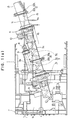
- Fig. 1(a) is a cross sectional view of a shield machine employing the earth pressure system shield process according to an embodiment of the present invention
- Fig. 1(b) is a view explaining Fig. 1(a)
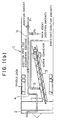
- Fig. 2 is a view explaining another embodiment
- Fig. 3 is a block diagram showing a control procedure of measurement.
- 1 is a shield machine
- 2 is a cutter head provided at the front portion of the shield machine for discharging an agent for improving fluidity and viscosity, a so-called excavation additive composed of bentonite, clay, water and the like and cutting and excavating the soil by the rotation thereof
- 1b is a mixing chamber for introducing the excavated soil thereinto and mixing the excavated soil with the excavation additive introduced thereinto from an excavation additive introduction tube to thereby fluidify the resultant mixture plastically.
- the excavation additive is manufactured outside a shield pit.
- the excavation additive is conveyed inside the shield pit by a pump P1 and a conveying pipe 4 and passes an excavation additive introduction pipe 1c communicating with the conveying pipe 4 and introduced into the earth by the cutter head 2 and thereafter mixed with the excavated soil in the mixing chamber 1b.
- the mud improving main agent in the form of slurry is conveyed through the conveying pipe 4 and mixed with the excavated soil depending on the excavation speed of the shield machine 1, i.e. the amount of the excavated soil and the nature of the excavated soil.
- the resultant mixture is introduced into the working face and mixed with the excavated soil in the mixing chamber 1b so that the mud improving main agent is uniformly dispersed into the excavated soil.
- the mud improving main agent can be mixed with the excavation additive at the excavation additive mud manufacturing plant located outside the shield pit or mixed with water at the back of the shield machine 1 and formed as the slurry and introduced into the excavation introduction pipe 1c through an introduction pump P2.
- the mud improving main agent is introduced into the working face, the mud improving main agent is introduced through the excavation additive introduction pipe 1c or through an exclusive introduction pipe provided in the shield machine 1 independently from the introduction pipe 1c.
- the introduction pump P2 detects the excavation speed of the shield machine 1 and adjusts the amount of the mud improving main agent to be supplied therefrom and has a regulator, not shown, capable of introducing at the proper ratio to the excavated soil.
- the mud improving main agent comprises a chemical for improving the soil by introducing into and mixing with the mud e.g. a coagulant composed of a natural vegetable chemical such as "ERFRESH" (Japanese Trade Mark Registration No. 2,304,178 owned by one of the assignees of the present application) as a main ingredient.
- a coagulant composed of a natural vegetable chemical such as "ERFRESH" (Japanese Trade Mark Registration No. 2,304,178 owned by one of the assignees of the present application) as a main ingredient.
- the surface of the mud improving main agent is sealed so as not to be disolved in water.
- the soil discharge screw conveyor 3 comprises a first conveying screw conveyor 31 arranged linearly by way of a shutter 14, a second conveying screw conveyor 32 and a mixing screw conveyor 33 disposed over the second conveying screw conveyor 32 and the shutter 14 disposed between the first and the second conveying screw conveyors 31 and 32 for communicating therewith.
- the first conveying screw conveyor 31 is housed in a cylindrical case 3a having a tip end portion opened into the shield chamber 1b while a hole for communicating with the mud improving assistant agent introduction pipe 5 is defined at the rear portion of a separating wall 1a over the case 3a.
- the mud improving assistant agent has a function to chemically remove the seal covered by the mud improving main agent.
- the mud improving assistant agent is introduced into the soil discharge screw conveyor 3 from the mud improving assistant agent introduction pipe 5 and added to the mud in the proper proportion to the conveying amount of the mud so that the mud improving assistant agent is mixed with the mud in the screw conveyor 3, thereby rendering the mud to have no fluidity.
- the mixing of the mud improving assistant agent with the mud can be made by the first conveying screw conveyor 31 alone where no second conveying screw conveyor 32 is installed. If the soil discharge screw conveyor is composed of a ribbon screw conveyor, the position of the introduction port can be changed appropriately as shown in Fig. 2 so that the mixing ratio can be regulated. If the screw conveyor is composed of a screw conveyor having a shaft attached thereto, the mixing can be made by providing a mixing assistant screw.
- the shutter 14 comprises a closing cylinder 14b provided at both sides thereof and a shutter plate 14a which is vertically closable by the closing cylinder 14b.
- a closing cylinder 14b provided at both sides thereof
- a shutter plate 14a which is vertically closable by the closing cylinder 14b.
- the mixing screw conveyor 33 facilitates the solidification by mixing the excavated soft mud having high fluidity but not sufficiently solidified by the first conveying screw conveyor 31 with the soil improving agent and forms a cut-off plug zone by compressing the soil.
- the mixing screw conveyor 33 is rotatably driven by a drive motor 8 provided at the rear end of the case 3b through a reduction gear 9 to thereby form the cut-off plug zone inside the case 3b by the operation, described later.
- the soil mixed sufficiently with the soil improving agent by the mixing screw conveyor 33 and solidified thereby is fed into the case 3c of the second conveying screw conveyor 32.
- the second conveying screw conveyor 32 is rotatably driven by a drive motor 10 provided at the rear end portion of the case 3c through a reduction gear 11 so that the solidified soil is conveyed in the rearward direction of the case 3c.
- the mixing of the soil with the soil improving agent and the conveyance of the resultant mixture are successively made by the first conveying screw conveyor 31, the mixing screw conveyor 33 and the second conveying screw conveyor 32 so that the improved soil is successively compressed and filled in the rear portion 16 of the second conveying screw conveyor 32, thereby forming the cut-off plug zone for resisting the hydraulic pressure influencing the working face.
- a cylinder portion 15 having no soil and gravel conveyor means is provided at the rear end portion of the second conveying screw conveyor 32 so that the excavated soil is discharged from the end portion of the cylinder portion 15.
- a shutter 12 is provided at the rear end of the case 3c and comprises a closing cylinder 12b and a shutter plate 12a which is vertically closable by the closing cylinder 12b.
- a hopper 13 protrudes from a rear side of the shutter 12.
- the soil conveyed by the second conveying screw conveyor 32 drops on the conveying vehicle such as a truck and a belt conveyor for discharging the soil by way of the hopper 13 when the shutter 12 is open.
- the cylinder portion 15 resists the conveyance of the soil and has a function to compress and fill the improved soil into the rear portion 16 of the second conveying screw conveyor 32 with assuraance.
- the resistance of the cylinder portion 15 against the conveyance of the soil can be regulated by regulating the length of the cylinder portion 15 or gradually reducing the cross-sectional area of the cylinder portion 15 toward the rear portion thereof.
- the soil improved by the excavation additive is recovered in density at the state before the excavation additive is mixed with the soil so that the cylinder portion 15 can resist the hydraulic pressure influencing the working face with the shearing resistance possessed by the soil and the blades of the screw conveyor.
- a fibrous shearing resistance reinforcing member can be added in the soil.
- Fig. 3 is a block diagram showing a measuring control procedure in which supplied to a controller 30 are input signals from a shield jack stroke detector 21, a shield jack speed detector 22, a screw conveyor rpm detector 23, a screw conveyor torque detector 24, a discharge soil flowing speed detector 25, a discharge soil density detector 26, an excavation additive addition amount measuring device 27, an improving main agent addition amount measuring device 28 and an improving assistant agent addition amount measuring device 29.
- the controller 30 supplies data into or receives the data from a memory 31 so that the addition amounts of the improving main agent 32 and the improving assistant agent 33 are determined.
- the addition of the improving main agent is controlled in interlocking relation with the shield jack speed while the addition of the improving assistant agent is controlled in interlocking relation with the rpm of the screw or the measured discharged amount of the soil.
- the addition amounts of the mud improving main agent and the mud improving assistant agent are regulated by measuring and deciding whether the improvement of the excavated mud and the formation of the cut-off plug zone are respectively made or not in the soil discharge screw conveyors while the discharge amount of the soil from the soil discharge screw conveyors are measured, thereby deciding as to whether an excessive excavation made at the working face disturbs the earth at the periphery of the working face.
- an excavation additive consisiting of the mixture of the agent for improving fluidity and viscosity of excavated soil and the mud improving main agent is added to the excavated soil at the time of shield excavation at the working face, inside the mixing chamber of the shield machine and inside the discharge screw conveyor, thereby sufficiently mixing the excavated soil with the improving main agent. Thereafter, the seal covering the improving main agent is removed chemically by the mud improving assistant added to the mud in the soil discharge screw conveyor. Inasmuch as the excavated soil is improved into a high quality soil having low fluidity inside the soil discharge screw conveyor, it is possible to effect the sufficient mixture of the soil and the excavation additive and the improvement of the soil by the shield machine having the small diameter without providing the specific mixer.
- the improving main agent and the improving assistant are mixed with each other continuously, and at the same time the cut-off plug zone is formed inside the discharge screw conveyor for resisting the hydraulic pressure influencing the shielded front portion, thereby preventing the explosion of the discharged soil, to prevent collapse of the working face and to make the soil discharge work easy.
Landscapes
- Engineering & Computer Science (AREA)
- Mining & Mineral Resources (AREA)
- Environmental & Geological Engineering (AREA)
- Life Sciences & Earth Sciences (AREA)
- General Life Sciences & Earth Sciences (AREA)
- Geochemistry & Mineralogy (AREA)
- Geology (AREA)
- Chemical & Material Sciences (AREA)
- Chemical Kinetics & Catalysis (AREA)
- General Chemical & Material Sciences (AREA)
- Excavating Of Shafts Or Tunnels (AREA)
Abstract
Claims (7)
- Procédé d'établissement d'écran par système à pression terrestre comprenant le creusement de terrain souterrain à partir du front d'avancement d'un creusement de tunnel souterrain, l'évacuation de la boue constituée de terrain excavé et d'eau dans une chambre de mélange puis le transport de la boue par un transporteur à vis d'évacuation de terrain vers un endroit écarté dudit front d'avancement et de ladite chambre de mélange, dans lequel un agent d'amélioration de boue est utilisé pour fixer les propriétés de viscosité de la boue, caractérisé par- l'introduction dans la région dudit front d'avancement d'un additif de creusement comprenant- un agent améliorant la fluidité et la viscosité du terrain excavé et- un agent principal d'amélioration de boue efficace pour coaguler le terrain,ledit agent principal d'amélioration de boue introduit dans ladite région étant recouvert d'un revêtement insoluble dans l'eau de façon à ne pas agir en coagulant le terrain dans ladite région,
ledit additif de creusement étant uniformément dispersé dans ladite boue dans ladite région, dans ladite chambre de mélange et dans ledit transporteur à vis d'évacuation de terrain afin de former une boue présentant une fluidité et une viscosité importantes,- puis l'addition et le mélange, avec la boue déplacée sur le transporteur à vis d'évacuation de terrain, d'un agent auxiliaire d'amélioration de boue efficace pour retirer chimiquement le revêtement insoluble dans l'eau de l'agent principal d'amélioration de boue,
ce par quoi ledit agent principal d'amélioration de boue devient alors actif pour coaguler le terrain excavé afin de transformer celui-ci en terrain coagulé de grande qualité, en particulier en terrain de grande qualité présentant une fluidité réduite. - Procédé selon la revendication 1, caractérisé en ce que ledit agent principal d'amélioration de boue et ledit agent auxiliaire d'amélioration de boue sont mélangés à l'intérieur du transporteur à vis d'évacuation de terrain, et une zone de bouchon obturateur est formée afin de maintenir la pression hydraulique agissant sur le front d'avancement du creusement de tunnel souterrain.
- Procédé selon la revendication 1 ou 2, caractérisé en ce qu'une partie cylindrique, ne comportant pas de moyen de transport, est disposée à l'extrémité arrière du transporteur à vis d'évacuation de terrain de manière à former un bouchon obturateur et à permettre le creusement au niveau du front d'avancement sous une forte pression hydraulique.
- Appareil d'établissement d'écran par système à pression terrestre permettant le creusement de terrain souterrain à partir du front d'avancement d'un creusement de tunnel souterrain, comprenant un transporteur à vis d'évacuation de terrain permettant d'amener une boue constituée de terrain excavé et d'eau ayant été évacuée dans une chambre de mélange vers un endroit écarté dudit front d'avancement et de ladite chambre de mélange, dans lequel un agent d'amélioration de boue est utilisé pour fixer les propriétés de viscosité de la boue, caractérisé en ce que ledit transporteur à vis d'évacuation de terrain (3) est divisé en premier et second transporteurs à vis d'évacuation de terrain (3₁, 3₂), dans lesquels ledit premier transporteur à vis d'évacuation de terrain (3₁) diminue la fluidité du terrain visqueux et fluide qui contient un additif de creusement uniformément dispersé comprenant au moins un agent principal d'amélioration de boue efficace pour coaguler le terrain, mais recouvert d'un revêtement insoluble dans l'eau pour empêcher son action, grâce à l'addition d'un agent auxiliaire d'amélioration de boue efficace pour retirer chimiquement le revêtement insoluble dans l'eau dudit agent principal d'amélioration de boue, améliorant ainsi ledit terrain excavé, et ledit second transporteur à vis d'évacuation (3₂) compacte ledit terrain excavé amélioré et évacue ledit terrain excavé amélioré compacté.
- Appareil selon la revendication 4, caractérisé en ce que lesdits premier et second transporteurs à vis d'évacuation (3₁, 3₂) possèdent respectivement des sources motrices rotatives qui tournent dans des sens opposés, c'est-à-dire l'une tournant dans le sens normal et l'autre tournant dans le sens opposé, afin de remuer ladite boue devant être évacuée à la frontière desdits premier et second transporteurs à vis d'évacuation (3₁,3₂), de manière à aider au mélange dudit agent principal d'amélioration de boue.
- Appareil selon la revendication 4, caractérisé en ce que ledit second transporteur à vis d'évacuation (3₂) inclut une zone de bouchon obturateur formée par un espace cylindrique (15) dont la structure prolonge une partie extrémale (16) dudit second transporteur à vis d'évacuation (3₂) et un volet (12) et une porte d'évacuation et dans lequel ledit terrain évacué est compacté et évacué par ladite porte d'évacuation.
- Appareil selon la revendication 6, caractérisé en ce qu'un troisième transporteur à vis d'évacuation (3₃) est installé en faisant partie dudit transporteur à vis d'évacuation (3), dans lequel ledit premier transporteur à vis d'évacuation (3₁) est disposé au niveau de ladite chambre de mélange (1b), ledit second transporteur à vis d'évacuation (3₂) est disposé au niveau de la partie qui prolonge ledit premier transporteur à vis d'évacuation (3₁) et ledit troisième transporteur à vis d'évacuation (3₃) est disposé au-dessus d'un volet (14) qui est placé au niveau de la séparation entre les premier et second transporteurs à vis d'évacuation, en étant intermédiaire entre ceux-ci de façon à former un trajet d'évacuation de dérivation dudit premier transporteur à vis d'évacuation audit second transporteur à vis d'évacuation afin d'aider au mélange dudit agent auxiliaire d'amélioration de boue au niveau dudit troisième transporteur à vis d'évacuation (3₃).
Applications Claiming Priority (5)
| Application Number | Priority Date | Filing Date | Title |
|---|---|---|---|
| JP10740289A JPH06100058B2 (ja) | 1989-04-28 | 1989-04-28 | 土圧系シールド工法 |
| JP107402/89 | 1989-04-28 | ||
| JP1107401A JPH02289791A (ja) | 1989-04-28 | 1989-04-28 | 高水圧の作用する地山でシールド工事を行うことのできる土圧系シールド工法 |
| JP107401/89 | 1989-04-28 | ||
| PCT/JP1990/000539 WO1990013733A1 (fr) | 1989-04-28 | 1990-04-25 | Procede d'excavation par bouclier s'opposant a la pression de la terre du front d'excavation |
Publications (3)
| Publication Number | Publication Date |
|---|---|
| EP0470253A1 EP0470253A1 (fr) | 1992-02-12 |
| EP0470253A4 EP0470253A4 (en) | 1992-10-21 |
| EP0470253B1 true EP0470253B1 (fr) | 1996-03-20 |
Family
ID=26447442
Family Applications (1)
| Application Number | Title | Priority Date | Filing Date |
|---|---|---|---|
| EP90906375A Expired - Lifetime EP0470253B1 (fr) | 1989-04-28 | 1990-04-25 | Procede d'excavation par bouclier s'opposant a la pression de la terre du front d'excavation |
Country Status (5)
| Country | Link |
|---|---|
| US (1) | US5180252A (fr) |
| EP (1) | EP0470253B1 (fr) |
| KR (1) | KR970007380B1 (fr) |
| DE (1) | DE69026083T2 (fr) |
| WO (1) | WO1990013733A1 (fr) |
Families Citing this family (11)
| Publication number | Priority date | Publication date | Assignee | Title |
|---|---|---|---|---|
| FR2728298A1 (fr) * | 1994-12-16 | 1996-06-21 | Condat Sa | Produit et procede pour la lubrification des surfaces metalliques d'un tunnelier a pression de terre |
| FR2764332B1 (fr) * | 1997-06-09 | 1999-09-03 | Nfm Tech | Dispositif d'evacuation des deblais dans un tunnelier |
| DE29914815U1 (de) * | 1999-08-09 | 2000-12-21 | Wirth Maschinen- und Bohrgeräte-Fabrik GmbH, 41812 Erkelenz | Fördereinrichtung für Bohrgut |
| GB9918992D0 (en) | 1999-08-12 | 1999-10-13 | Mbt Holding Ag | Method |
| DE29915329U1 (de) * | 1999-08-25 | 2001-01-11 | Wirth Maschinen- und Bohrgeräte-Fabrik GmbH, 41812 Erkelenz | Fördereinrichtung für Bohrgut |
| EP2039881A1 (fr) * | 2007-09-18 | 2009-03-25 | Bouygues Travaux Publics | Procédé pour la détermination d'additifs utilisés dans des machines de perçage de galerie |
| EP2284360A1 (fr) * | 2009-08-14 | 2011-02-16 | Meyer & John GmbH & Co. KG | Procédé d'avancée |
| DE102012219134A1 (de) * | 2012-10-19 | 2012-12-27 | Herrenknecht Ag | Verfahren und Vorrichtung zum Abfördern von Abraum im Tunnelvortrieb |
| CN102926762B (zh) * | 2012-11-22 | 2015-02-11 | 中铁工程装备集团有限公司 | 一种防爆型tbm |
| CN112855188B (zh) * | 2021-01-13 | 2022-04-29 | 中铁广州工程局集团有限公司 | 一种地铁工程软土地层土压平衡盾构施工方法 |
| CN117927265B (zh) * | 2024-01-19 | 2025-10-17 | 三联泵业股份有限公司 | 隧道掘进机用排浆泵机构及排浆方法 |
Citations (2)
| Publication number | Priority date | Publication date | Assignee | Title |
|---|---|---|---|---|
| JPS5387534A (en) * | 1977-01-11 | 1978-08-02 | Hitachi Shipbuilding Eng Co | Shield excavator |
| JPS5729792A (en) * | 1980-07-25 | 1982-02-17 | Kumagai Gumi Co Ltd | Disposal of air-bubble-mixed sludge |
Family Cites Families (9)
| Publication number | Priority date | Publication date | Assignee | Title |
|---|---|---|---|---|
| GB1083322A (en) * | 1964-03-21 | 1967-09-13 | Mott Hay & Anderson | Improvements in or relating to tunnelling apparatus and methods of tunnelling |
| GB1391499A (en) * | 1972-10-13 | 1975-04-23 | Nat Res Dev | Device for passing material from the pressurised side to the non-pressurised side of a bulk-head |
| US3830545A (en) * | 1973-08-01 | 1974-08-20 | Robbins Co | Shield tunneling machine with orbiting cutterhead |
| US4165129A (en) * | 1977-11-17 | 1979-08-21 | Ishikawajima-Harima Jukogyo Kabushiki Kaisha | Shield tunneling machine and method |
| JPS55165397A (en) * | 1979-06-06 | 1980-12-23 | Hitachi Shipbuilding Eng Co | Control of soil discharging device for shield excavator |
| DE3437996A1 (de) * | 1984-10-17 | 1986-04-24 | Ed. Züblin AG, 7000 Stuttgart | Vortriebsschild mit fluidstuetzung |
| JPS61216994A (ja) * | 1985-03-19 | 1986-09-26 | 大豊建設株式会社 | 排土改良方法 |
| US4915541A (en) * | 1985-08-19 | 1990-04-10 | Thompson Louis J | Method and apparatus for continuously boring and lining tunnels and other like structures |
| DE3622851A1 (de) * | 1986-07-08 | 1988-01-21 | Hochtief Ag Hoch Tiefbauten | Erddruckschild |
-
1990
- 1990-04-25 US US07/768,981 patent/US5180252A/en not_active Expired - Fee Related
- 1990-04-25 WO PCT/JP1990/000539 patent/WO1990013733A1/fr not_active Ceased
- 1990-04-25 DE DE69026083T patent/DE69026083T2/de not_active Expired - Fee Related
- 1990-04-25 EP EP90906375A patent/EP0470253B1/fr not_active Expired - Lifetime
-
1991
- 1991-10-28 KR KR91701469A patent/KR970007380B1/ko not_active Expired - Fee Related
Patent Citations (2)
| Publication number | Priority date | Publication date | Assignee | Title |
|---|---|---|---|---|
| JPS5387534A (en) * | 1977-01-11 | 1978-08-02 | Hitachi Shipbuilding Eng Co | Shield excavator |
| JPS5729792A (en) * | 1980-07-25 | 1982-02-17 | Kumagai Gumi Co Ltd | Disposal of air-bubble-mixed sludge |
Also Published As
| Publication number | Publication date |
|---|---|
| DE69026083T2 (de) | 1996-08-22 |
| WO1990013733A1 (fr) | 1990-11-15 |
| EP0470253A4 (en) | 1992-10-21 |
| EP0470253A1 (fr) | 1992-02-12 |
| DE69026083D1 (de) | 1996-04-25 |
| KR970007380B1 (en) | 1997-05-08 |
| US5180252A (en) | 1993-01-19 |
Similar Documents
| Publication | Publication Date | Title |
|---|---|---|
| US4165129A (en) | Shield tunneling machine and method | |
| EP0042993B1 (fr) | Procédé et machine pour le percement de tunnels avec bouclier | |
| EP0470253B1 (fr) | Procede d'excavation par bouclier s'opposant a la pression de la terre du front d'excavation | |
| US4607889A (en) | Shield tunnel boring machine | |
| KR0175170B1 (ko) | 시일드 굴진기에 있어서의 토질개량 제어장치 | |
| CN85104514A (zh) | 屏蔽式隧道挖掘机 | |
| US5222839A (en) | Method and apparatus for underwater reclamation | |
| JPH06100058B2 (ja) | 土圧系シールド工法 | |
| JPH10169365A (ja) | 軟弱土用シールド工法および掘削液添加剤 | |
| JP3150298B2 (ja) | トンネルの掘進方法およびシールド機 | |
| JP2589170B2 (ja) | 高含水ズリ処理剤を使用した土圧シールド残土処理方法 | |
| JP3124368B2 (ja) | 土圧シールド掘進工法 | |
| JPH04203093A (ja) | 泥土圧式シールド掘進機 | |
| JPS62318B2 (fr) | ||
| JP2530287B2 (ja) | 泥水排土式撹拌掘進機 | |
| JPH0332640Y2 (fr) | ||
| JPS59213897A (ja) | シ−ルド掘削装置 | |
| JPH0842288A (ja) | シールド掘進機及びそのシール方法 | |
| CN85104500A (zh) | 遮护式隧道掘削机 | |
| JPH07113319B2 (ja) | シールド堀進機の排土噴発防止工法 | |
| JPH02289791A (ja) | 高水圧の作用する地山でシールド工事を行うことのできる土圧系シールド工法 | |
| JP3343763B2 (ja) | 泥土圧シールド工法における切羽安定方法 | |
| JP2707203B2 (ja) | シールド掘進方法 | |
| JPH03158599A (ja) | シールド掘進機の排土処理方法及び排土処理装置 | |
| JPH08333983A (ja) | 土丹層用シールド工法 |
Legal Events
| Date | Code | Title | Description |
|---|---|---|---|
| PUAI | Public reference made under article 153(3) epc to a published international application that has entered the european phase |
Free format text: ORIGINAL CODE: 0009012 |
|
| 17P | Request for examination filed |
Effective date: 19911017 |
|
| AK | Designated contracting states |
Kind code of ref document: A1 Designated state(s): DE FR GB |
|
| A4 | Supplementary search report drawn up and despatched |
Effective date: 19920831 |
|
| AK | Designated contracting states |
Kind code of ref document: A4 Designated state(s): DE FR GB |
|
| 17Q | First examination report despatched |
Effective date: 19931103 |
|
| GRAH | Despatch of communication of intention to grant a patent |
Free format text: ORIGINAL CODE: EPIDOS IGRA |
|
| GRAA | (expected) grant |
Free format text: ORIGINAL CODE: 0009210 |
|
| AK | Designated contracting states |
Kind code of ref document: B1 Designated state(s): DE FR GB |
|
| REF | Corresponds to: |
Ref document number: 69026083 Country of ref document: DE Date of ref document: 19960425 |
|
| ET | Fr: translation filed | ||
| PLBE | No opposition filed within time limit |
Free format text: ORIGINAL CODE: 0009261 |
|
| STAA | Information on the status of an ep patent application or granted ep patent |
Free format text: STATUS: NO OPPOSITION FILED WITHIN TIME LIMIT |
|
| 26N | No opposition filed | ||
| PGFP | Annual fee paid to national office [announced via postgrant information from national office to epo] |
Ref country code: FR Payment date: 19980409 Year of fee payment: 9 |
|
| PGFP | Annual fee paid to national office [announced via postgrant information from national office to epo] |
Ref country code: GB Payment date: 19980416 Year of fee payment: 9 |
|
| PGFP | Annual fee paid to national office [announced via postgrant information from national office to epo] |
Ref country code: DE Payment date: 19980504 Year of fee payment: 9 |
|
| PG25 | Lapsed in a contracting state [announced via postgrant information from national office to epo] |
Ref country code: GB Free format text: LAPSE BECAUSE OF NON-PAYMENT OF DUE FEES Effective date: 19990425 |
|
| GBPC | Gb: european patent ceased through non-payment of renewal fee |
Effective date: 19990425 |
|
| PG25 | Lapsed in a contracting state [announced via postgrant information from national office to epo] |
Ref country code: FR Free format text: LAPSE BECAUSE OF NON-PAYMENT OF DUE FEES Effective date: 19991231 |
|
| REG | Reference to a national code |
Ref country code: FR Ref legal event code: ST |
|
| PG25 | Lapsed in a contracting state [announced via postgrant information from national office to epo] |
Ref country code: DE Free format text: LAPSE BECAUSE OF NON-PAYMENT OF DUE FEES Effective date: 20000201 |