EP0470265B1 - Structure d'equilibrage pour moteur - Google Patents
Structure d'equilibrage pour moteur Download PDFInfo
- Publication number
- EP0470265B1 EP0470265B1 EP91904462A EP91904462A EP0470265B1 EP 0470265 B1 EP0470265 B1 EP 0470265B1 EP 91904462 A EP91904462 A EP 91904462A EP 91904462 A EP91904462 A EP 91904462A EP 0470265 B1 EP0470265 B1 EP 0470265B1
- Authority
- EP
- European Patent Office
- Prior art keywords
- motor
- output shaft
- balancing
- internally threaded
- disk
- Prior art date
- Legal status (The legal status is an assumption and is not a legal conclusion. Google has not performed a legal analysis and makes no representation as to the accuracy of the status listed.)
- Expired - Lifetime
Links
Images



Classifications
-
- F—MECHANICAL ENGINEERING; LIGHTING; HEATING; WEAPONS; BLASTING
- F16—ENGINEERING ELEMENTS AND UNITS; GENERAL MEASURES FOR PRODUCING AND MAINTAINING EFFECTIVE FUNCTIONING OF MACHINES OR INSTALLATIONS; THERMAL INSULATION IN GENERAL
- F16F—SPRINGS; SHOCK-ABSORBERS; MEANS FOR DAMPING VIBRATION
- F16F15/00—Suppression of vibrations in systems; Means or arrangements for avoiding or reducing out-of-balance forces, e.g. due to motion
- F16F15/32—Correcting- or balancing-weights or equivalent means for balancing rotating bodies, e.g. vehicle wheels
- F16F15/322—Correcting- or balancing-weights or equivalent means for balancing rotating bodies, e.g. vehicle wheels the rotating body being a shaft
-
- F—MECHANICAL ENGINEERING; LIGHTING; HEATING; WEAPONS; BLASTING
- F16—ENGINEERING ELEMENTS AND UNITS; GENERAL MEASURES FOR PRODUCING AND MAINTAINING EFFECTIVE FUNCTIONING OF MACHINES OR INSTALLATIONS; THERMAL INSULATION IN GENERAL
- F16F—SPRINGS; SHOCK-ABSORBERS; MEANS FOR DAMPING VIBRATION
- F16F15/00—Suppression of vibrations in systems; Means or arrangements for avoiding or reducing out-of-balance forces, e.g. due to motion
- F16F15/30—Flywheels
-
- H—ELECTRICITY
- H02—GENERATION; CONVERSION OR DISTRIBUTION OF ELECTRIC POWER
- H02K—DYNAMO-ELECTRIC MACHINES
- H02K15/00—Processes or apparatus specially adapted for manufacturing, assembling, maintaining or repairing of dynamo-electric machines
- H02K15/16—Centring rotors within the stators
- H02K15/165—Balancing the rotors
-
- H—ELECTRICITY
- H02—GENERATION; CONVERSION OR DISTRIBUTION OF ELECTRIC POWER
- H02K—DYNAMO-ELECTRIC MACHINES
- H02K7/00—Arrangements for handling mechanical energy structurally associated with dynamo-electric machines, e.g. structural association with mechanical driving motors or auxiliary dynamo-electric machines
- H02K7/04—Balancing means
Definitions
- the present invention relates to the construction of a general-purpose industrial electric motor, by which the vibration and noise are reduced, and more particularly, to a motor balancing structure for balancing such an electric motor.
- the parts and components of the motor must be mounted on an external drive means of a commercial balancing machine, to be dynamically balanced individually, but since the external drive means of the commercial balancing machine can rotate the parts only at 3,000 r.p.m. at most, the commercial balancing machine is incapable of detecting a small imbalance thereof.
- an object of the present invention is to provide a low cost, balanced motor structure capable of balancing a motor so that the motor is able to operate in a well-balanced state over the entire operating speed range.
- US-A-2249834 discloses an apparatus comprising an electric motor having a rotating output shaft provided with axially opposite external ends and a balancing structure comprising a respective disk member fixedly attached to each end of the output shaft, each of the disk members having axially inner and outer surfaces formed perpendicular to the axis of rotation of the output shaft; and according to the present invention, such an apparatus is characterised by the axially outer surfaces of each of said disk members having defined thereon a plurality of internally threaded holes, the plurality of internally threaded holes being externally exposed so as to enable an operator to access the plurality of internally threaded holes, at least one of the disk members being a labyrinth seal; and a plurality of balancing screws of different lengths, wherein, in use, one of the screws is interchangeably screwed into a corresponding internally threaded hole in one of the two disk members, for interchangeably balancing the output shaft of the electric motor.
- a front bearing 20F and a rear bearing 20R are fitted in a front housing 16 and a rear housing 18 provided on the front and rear ends of a stator 10, respectively.
- a rotor 12 integrally combined with an output shaft 14 supported for rotation by the bearings 20F and 20R is disposed radially opposite to the stator 10.
- the components 24G and 24S of a rotation detector for detecting the rotational position and/or the rotational speed of the output shaft 14 are provided in connection with the rear portion of the output shaft 14.
- the front and rear ends of the output shaft 14 extend outside the front housing 16 and the rear housing 18, respectively.
- the motor is provided with labyrinth seals at the front and rear ends thereof, i.e., in the front end of the front housing 16 and in the rear end of the rear housing 18, respectively, to prevent the entry of oil mist and the like contained in the ambient atmosphere to the inside of the motor through gaps between the output shaft and the front housing 16, and between the output shaft and the rear housing 18. Accordingly, disk-like members 22F and 22R forming the labyrinth seals in combination with the front housing 16 and the rear housing 18 are fixed to the front and rear ends of the output shaft 14, respectively.
- the balanced motor structure of the first embodiment of the present invention is characterized by balancing the motor by using the front disk-like member 22F and the rear disk-like member 22R, after the completion of the assembly of the motor.
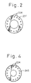
- the disk-like member 22F ( 22R ) is provided, in an outer surface thereof exposed to the outside, with a plurality of internally threaded holes (in this embodiment, sixteen internally threaded holes ) 22A at the same radial positions and at equal angular intervals.
- the motor shown in Fig. 1 is rotated under its own drive power on a commercial field dynamic balancer, so that the rotational speed of the output shaft 14 is gradually increased to a maximum rotational speed of, for example, 15,000 r.p.m., to measure an imbalance thereof.
- a balancing screw 26 capable of being engaged in the internally threaded hole 22A is screwed in the internally threaded hole 22A to an appropriate point at which the measured imbalance is dynamically adjusted to the least possible extent.
- the internally threaded holes 22a in both the front and rear disks 22F and 22R can be used for the balancing of the motor, the accuracy of the adjustment of the balance of the motor can be increased.
- the selective use of a plurality of kinds of balancing screws 26 having different lengths further improves the balancing accuracy. For an even more accurate balancing. portions of the disk-like members 22F and 22R may be drilled to desired depths to thereby remove any residual imbalance of the motor.
- FIG. 3 The construction of the rear portion of an electric motor shown in Fig. 3 incorporating a balancing structure according to the second embodiment of the present invention is different from that of the rear portion of the motor shown in Fig. 1.
- the rear end of an output shaft 14 terminates at the components 24G and 24S of a rotational speed detector, and a cooling fan 30 is disposed behind the output shaft 14.
- the cooling fan 30 and the rear cover 18a of a rear housing 18 are temporarily removed.
- a front disk-like member 22F provided at the front end of the motor, and the gear member 24G of the rotational speed detector on the rear end are formed with internally threaded holes 22A at equal angular intervals, as shown in Fig. 2, and balancing screws 26 are screwed in the internally threaded holes 22A, to appropriate points, to thereby eliminate an imbalance measured by the balancing machine
- Figure 4 illustrates the gear member 24G viewed in the direction of the arrow C.
- Figure 5 illustrates an electric motor provided with a hollow output shaft 14′, instead of the output shaft 14 of the motor of Fig. 1.
- the hollow output shaft 14′ has a front end provided with a coupling member 34, and a rear end connected to a rotary joint 32.
- the present invention is also applicable to the balancing of the motor to be used in a mode such as illustrated in Fig. 5.
- the imbalance of an electric motor can be all but eliminated after completely assembling the motor, simply by using balancing screws. Since the disk-like members for the labyrinth seals and the gear member of the rotational speed detector for receiving the balancing screws are integral components of the electric motor, the use of the disk-like members for the labyrinth seals or the gear as the means of obtaining a dynamic balancing of the motor does not appreciably increase the manufacturing cost of the motor. Furthermore, since the motor is balanced after the completion of the assembly of the motor, the resultant balance of the motor is very accurate.
Landscapes
- Engineering & Computer Science (AREA)
- General Engineering & Computer Science (AREA)
- Power Engineering (AREA)
- Physics & Mathematics (AREA)
- Acoustics & Sound (AREA)
- Aviation & Aerospace Engineering (AREA)
- Mechanical Engineering (AREA)
- Manufacturing & Machinery (AREA)
- Manufacture Of Motors, Generators (AREA)
- Connection Of Motors, Electrical Generators, Mechanical Devices, And The Like (AREA)
Abstract
Claims (3)
- Appareil comportant un moteur électrique ayant un arbre de sortie rotatif (14) pourvu d'extrémités externes axialement opposées et une structure d'équilibrage comportant un élément en forme de disque respectif (22F, 22R, 24G) fixé à chaque extrémité de l'arbre de sortie, chacun des éléments en forme de disque ayant des surfaces axialement interne et externe formées perpendiculairement à l'axe de rotation de l'arbre de sortie; caractérisé par le fait que les surfaces axialement externes de chacun des éléments en forme de disque ont plusieurs trous taraudés (22A) définis dedans, la multiplicité de trous taraudés étant exposée à l'extérieur de façon à permettre à un opérateur d'accéder à la multiplicité de trous taraudés, au moins un des éléments en forme de disque (22F, 22R) étant un joint à labyrinthe; et par plusieurs vis d'équilibrage (26) de différentes longueurs, une des vis, lors de l'utilisation, étant vissée de manière interchangeable dans un trou taraudé correspondant (22A) dans un des deux éléments en forme de disque (22F, 22R, 24G) afin d'équilibrer de manière interchangeable l'arbre de sortie du moteur électrique.
- Appareil selon la revendication 1, dans lequel un des éléments en forme de disque est constitué par des moyens d'engrenage de détection de vitesse de rotation (24G) ayant des dents d'engrenage formées sur sa circonférence extérieure.
- Appareil selon la revendication 1 ou la revendication 2, dans lequel les trous taraudés (22A) d'au moins un disque (22F, 22R, 22G) sont disposés à des distances radiales égales par rapport à l'axe de rotation de l'arbre de sortie, et à des intervalles angulaires égaux.
Applications Claiming Priority (3)
| Application Number | Priority Date | Filing Date | Title |
|---|---|---|---|
| JP44609/90 | 1990-02-27 | ||
| JP2044609A JP2716237B2 (ja) | 1990-02-27 | 1990-02-27 | モータのバランス構造 |
| PCT/JP1991/000187 WO1991013485A1 (fr) | 1990-02-27 | 1991-02-15 | Structure d'equilibrage pour moteur |
Publications (3)
| Publication Number | Publication Date |
|---|---|
| EP0470265A1 EP0470265A1 (fr) | 1992-02-12 |
| EP0470265A4 EP0470265A4 (en) | 1992-04-08 |
| EP0470265B1 true EP0470265B1 (fr) | 1995-10-04 |
Family
ID=12696188
Family Applications (1)
| Application Number | Title | Priority Date | Filing Date |
|---|---|---|---|
| EP91904462A Expired - Lifetime EP0470265B1 (fr) | 1990-02-27 | 1991-02-15 | Structure d'equilibrage pour moteur |
Country Status (5)
| Country | Link |
|---|---|
| US (1) | US5235228A (fr) |
| EP (1) | EP0470265B1 (fr) |
| JP (1) | JP2716237B2 (fr) |
| DE (1) | DE69113561T2 (fr) |
| WO (1) | WO1991013485A1 (fr) |
Families Citing this family (45)
| Publication number | Priority date | Publication date | Assignee | Title |
|---|---|---|---|---|
| DE9303470U1 (de) * | 1993-03-10 | 1994-07-14 | Robert Bosch Gmbh, 70469 Stuttgart | Gebläse |
| US5487640A (en) * | 1994-03-16 | 1996-01-30 | Dresser-Rand Company | Balancing rings for assembled steam turbines |
| KR0122703Y1 (ko) * | 1994-09-16 | 1998-10-01 | 김광호 | 모터 |
| DE29502564U1 (de) * | 1995-02-16 | 1996-06-20 | Siemens AG, 80333 München | Elektrische Maschine |
| US5831360A (en) * | 1995-12-15 | 1998-11-03 | Iai Corporation | Actuator |
| FR2766988B1 (fr) * | 1997-08-04 | 1999-09-24 | Gec Alsthom Moteurs Sa | Dispositif et procede d'equilibrage d'un rotor de machine tournante rapide |
| US6211587B1 (en) * | 1998-11-12 | 2001-04-03 | Hitachi, Ltd. | Electric rotating machine |
| US6097120A (en) * | 1999-09-04 | 2000-08-01 | Sunonwealth Electric Machine Industry Co., Ltd. | Brushless D.C. motor assembly |
| JP2001298903A (ja) * | 2000-04-10 | 2001-10-26 | Moric Co Ltd | ブラシレスdcモータ |
| US20040026883A1 (en) * | 2002-08-09 | 2004-02-12 | Ting-Hsing Chen | Generator structure for a tri-wheel scooter |
| DE10259179A1 (de) * | 2002-12-18 | 2004-07-08 | Robert Bosch Gmbh | Elektrisch angetriebene Luftpumpe und Verfahren zur Herstellung einer elektrisch angetriebenen Luftpumpe |
| BRPI0412816A (pt) * | 2003-07-21 | 2006-09-26 | Siemens Energy & Automation | balanceamento de plano central integral de um dispositivo elétrico giratório |
| US7109616B2 (en) * | 2003-10-16 | 2006-09-19 | Fasco Industries, Inc. | Electric motor with hall effect memory module |
| US7303377B2 (en) * | 2004-04-14 | 2007-12-04 | Pratt & Whitney Canada Corp. | Apparatus and method of balancing a shaft |
| DE102004044070B3 (de) * | 2004-09-11 | 2006-01-19 | Pierburg Gmbh | Unwuchtausgleichselement, Pumpe und Verfahren zum Auswuchten einer Pumpe |
| US7390179B2 (en) * | 2004-12-21 | 2008-06-24 | Emerson Climate Technologies, Inc. | Scroll machine having counterweights with changeable cavity |
| DE102005009928B3 (de) * | 2005-03-04 | 2006-06-14 | Bühler Motor GmbH | Elektromotor |
| US7342331B2 (en) * | 2005-10-25 | 2008-03-11 | Honeywell International, Inc. | Multi-plane flexible rotor balancing |
| EP1870988A1 (fr) * | 2006-06-22 | 2007-12-26 | ALSTOM Technology Ltd | Procédé et dispositif d'équilibrage d'un rotor d'une machine électrique |
| US20090033160A1 (en) * | 2007-07-31 | 2009-02-05 | Daniel Mueller | Electric motor for hybrid or electric vehicle |
| US8496194B2 (en) * | 2008-03-10 | 2013-07-30 | Finishing Brands Holdings Inc. | Method and apparatus for retaining highly torqued fittings in molded resin or polymer housing |
| US7926748B2 (en) * | 2008-03-10 | 2011-04-19 | Illinois Tool Works Inc. | Generator for air-powered electrostatically aided coating dispensing device |
| US7988075B2 (en) | 2008-03-10 | 2011-08-02 | Illinois Tool Works Inc. | Circuit board configuration for air-powered electrostatically aided coating material atomizer |
| US8590817B2 (en) * | 2008-03-10 | 2013-11-26 | Illinois Tool Works Inc. | Sealed electrical source for air-powered electrostatic atomizing and dispensing device |
| US8016213B2 (en) * | 2008-03-10 | 2011-09-13 | Illinois Tool Works Inc. | Controlling temperature in air-powered electrostatically aided coating material atomizer |
| US8770496B2 (en) | 2008-03-10 | 2014-07-08 | Finishing Brands Holdings Inc. | Circuit for displaying the relative voltage at the output electrode of an electrostatically aided coating material atomizer |
| CN102606600B (zh) * | 2011-01-19 | 2014-11-12 | 盈锡精密工业股份有限公司 | 锁制精密螺帽的平衡结构及其方法 |
| US20140124231A1 (en) | 2012-11-06 | 2014-05-08 | Milwaukee Electric Tool Corporation | Electric motor for a power tool |
| US10432045B2 (en) | 2012-11-06 | 2019-10-01 | Milwaukee Electric Tool Corporation | Electric motor for a power tool |
| DE102013207876A1 (de) * | 2013-04-30 | 2014-10-30 | Robert Bosch Gmbh | Elektromotor mit einem Stator und einem Rotor |
| DE102014215275A1 (de) | 2014-08-04 | 2016-02-04 | Volkswagen Aktiengesellschaft | Verfahren zur Verringerung oder Beseitigung von Unwuchten elektrischer Maschinen |
| JP6450711B2 (ja) | 2016-05-25 | 2019-01-09 | ファナック株式会社 | バランス構造を有する電動機及び該電動機を備える工作機械 |
| JP6450714B2 (ja) | 2016-06-24 | 2019-01-09 | ファナック株式会社 | バランス構造を有する端子箱付き電動機及び該電動機を備える工作機械 |
| JP6333916B2 (ja) * | 2016-10-24 | 2018-05-30 | ファナック株式会社 | 異物の侵入を抑制する電動機 |
| JP6905359B2 (ja) * | 2017-03-13 | 2021-07-21 | 住友重機械工業株式会社 | モータ及びピニオン軸の組み付け方法 |
| JP6652538B2 (ja) | 2017-10-06 | 2020-02-26 | ファナック株式会社 | モータおよび主軸保護構造 |
| JP6572286B2 (ja) * | 2017-10-26 | 2019-09-04 | ファナック株式会社 | モータおよび主軸保護構造 |
| JP6708701B2 (ja) * | 2018-06-13 | 2020-06-10 | ファナック株式会社 | 騒音低減構造を備えたフリンジャ及び該フリンジャを備えた電動機 |
| CN111463957A (zh) * | 2019-11-27 | 2020-07-28 | 安徽艾格赛特电机科技有限公司 | 电机动平衡调节装置及调节方法 |
| JP7525629B2 (ja) | 2020-09-30 | 2024-07-30 | ファナック株式会社 | 工作機械 |
| DE112022000236T5 (de) | 2021-01-07 | 2023-09-28 | Fanuc Corporation | Beobachtungsvorrichtung und Beobachtungsverfahren |
| WO2022149572A1 (fr) | 2021-01-07 | 2022-07-14 | ファナック株式会社 | Dispositif d'observation et procédé d'observation |
| US20240060844A1 (en) | 2021-01-07 | 2024-02-22 | Fanuc Corporation | Observation device and observation method |
| JP7658204B2 (ja) * | 2021-07-28 | 2025-04-08 | 日本精工株式会社 | モータ |
| DE102022206607A1 (de) | 2022-06-29 | 2024-01-04 | Mahle International Gmbh | Verfahren zur Herstellung eines Rotors einer elektrischen Maschine |
Family Cites Families (19)
| Publication number | Priority date | Publication date | Assignee | Title |
|---|---|---|---|---|
| DE527042C (de) * | 1931-06-13 | Sachsenwerk Licht & Kraft Ag | Elektrischer Kleinmotor | |
| US2249834A (en) * | 1940-07-12 | 1941-07-22 | Westinghouse Electric & Mfg Co | Balance-ring combination |
| US2557659A (en) * | 1945-11-13 | 1951-06-19 | Ingraham Elmer Clark | Dynamic balance indicating system |
| US2558737A (en) * | 1946-12-13 | 1951-07-03 | Master Electric Co | Rotor balancing means |
| FR1280370A (fr) * | 1961-02-14 | 1961-12-29 | Bbc Brown Boveri & Cie | Rotor de machine électrique comportant des masselottes d'équilibrage susceptibles d'être déplacées dans le sens longitudinal |
| US3512022A (en) * | 1968-02-21 | 1970-05-12 | Dictaphone Corp | Flywheel flutter filter |
| US3662197A (en) * | 1970-11-12 | 1972-05-09 | Gen Electric | Combination motor-clutch apparatus |
| US4143288A (en) * | 1974-07-13 | 1979-03-06 | Olympus Optical Co., Ltd. | Coreless motor |
| JPS5353503U (fr) * | 1976-10-12 | 1978-05-09 | ||
| US4082968A (en) * | 1976-11-23 | 1978-04-04 | Contraves-Goerz Corporation | Speed detector for use on a dc motor |
| JPS6016186B2 (ja) * | 1977-10-28 | 1985-04-24 | 三菱電機株式会社 | 回転体のバランス取り方法 |
| JPS54149601U (fr) * | 1978-04-11 | 1979-10-18 | ||
| JPS5543360U (fr) * | 1978-09-13 | 1980-03-21 | ||
| FR2461855A3 (fr) * | 1979-07-19 | 1981-02-06 | Leroy Somer Moteurs | Dispositif d'equilibrage pour machine tournante et moteur electrique s'y rapportant |
| JPS5662050A (en) * | 1979-10-22 | 1981-05-27 | Mitsubishi Electric Corp | Balancing method of rotor of electric motor |
| US4389586A (en) * | 1982-02-22 | 1983-06-21 | General Electric Company | Electric wheel with removable motor |
| DE3327744A1 (de) * | 1983-08-01 | 1985-02-21 | Siemens AG, 1000 Berlin und 8000 München | Verfahren zum auswuchten von bewickelten laeufern elektrischer maschinen |
| JPS60138417A (ja) * | 1983-12-27 | 1985-07-23 | Mitsubishi Heavy Ind Ltd | 電磁誘導を利用したロ−タリ式位置検出装置 |
| EP0161326A1 (fr) * | 1984-05-16 | 1985-11-21 | Mitsubishi Denki Kabushiki Kaisha | Volant d'inertie |
-
1990
- 1990-02-27 JP JP2044609A patent/JP2716237B2/ja not_active Expired - Fee Related
-
1991
- 1991-02-15 DE DE69113561T patent/DE69113561T2/de not_active Expired - Fee Related
- 1991-02-15 US US07/768,207 patent/US5235228A/en not_active Expired - Lifetime
- 1991-02-15 WO PCT/JP1991/000187 patent/WO1991013485A1/fr not_active Ceased
- 1991-02-15 EP EP91904462A patent/EP0470265B1/fr not_active Expired - Lifetime
Also Published As
| Publication number | Publication date |
|---|---|
| JPH03251066A (ja) | 1991-11-08 |
| WO1991013485A1 (fr) | 1991-09-05 |
| DE69113561D1 (de) | 1995-11-09 |
| US5235228A (en) | 1993-08-10 |
| JP2716237B2 (ja) | 1998-02-18 |
| EP0470265A1 (fr) | 1992-02-12 |
| DE69113561T2 (de) | 1996-04-25 |
| EP0470265A4 (en) | 1992-04-08 |
Similar Documents
| Publication | Publication Date | Title |
|---|---|---|
| US5235228A (en) | Motor balancing structure | |
| US5759128A (en) | Drive assembly having electric motor and differential gear device disposed within rotor of the motor | |
| US5676025A (en) | Apparatus for balancing a rotary member | |
| US4684330A (en) | Drive for rotary compressor | |
| EP0289610B1 (fr) | Structure de coussinet pour moteur a vitesse elevee | |
| CN114337159A (zh) | 一种可穿轴安装的电机式在线自动平衡装置 | |
| WO1989005412A1 (fr) | Dispositif annulaire d'equilibrage | |
| EP0115538A1 (fr) | Dispositif de couplage d'un servo moteur a un detecteur rotatif | |
| JPS63259242A (ja) | 回転体の自動バランス装置 | |
| CN220653084U (zh) | 电机和洗涤设备 | |
| JP3862844B2 (ja) | モータ構造 | |
| US5007305A (en) | Ring balancer | |
| US3159050A (en) | Dynamic balancing apparatus | |
| CN110871276A (zh) | 机床的电主轴 | |
| EP2045470A2 (fr) | Groupe d'équilibrage pour le rotor d'une machine rotative pour fluides | |
| WO1990016108A1 (fr) | Dispositif servant a exercer une precharge sur le roulement a rouleaux d'un moteur | |
| JP2009281462A (ja) | 静圧気体軸受スピンドル | |
| KR102655188B1 (ko) | Cnc공작기계의 스핀들, 베어링과 변속기어를 포함하는 스핀들계에 대한 건전성 진단방법 | |
| US4593564A (en) | Equilibrating apparatus in particular for motor vehicle wheels | |
| JP2004114254A (ja) | 主軸装置 | |
| WO2021105776A1 (fr) | Système et procédé d'équilibrage positif de rotors | |
| CN214281117U (zh) | 动平衡自动校正结构、转子组件、电机、空调和家用电器 | |
| JP3117259B2 (ja) | 回転角割出しアクチュエータ | |
| JP2517910Y2 (ja) | 光偏向器 | |
| JPH08154365A (ja) | モータ駆動回転機器 |
Legal Events
| Date | Code | Title | Description |
|---|---|---|---|
| PUAI | Public reference made under article 153(3) epc to a published international application that has entered the european phase |
Free format text: ORIGINAL CODE: 0009012 |
|
| 17P | Request for examination filed |
Effective date: 19911121 |
|
| AK | Designated contracting states |
Kind code of ref document: A1 Designated state(s): DE FR GB |
|
| A4 | Supplementary search report drawn up and despatched |
Effective date: 19920220 |
|
| AK | Designated contracting states |
Kind code of ref document: A4 Designated state(s): DE FR GB |
|
| 17Q | First examination report despatched |
Effective date: 19940328 |
|
| GRAA | (expected) grant |
Free format text: ORIGINAL CODE: 0009210 |
|
| AK | Designated contracting states |
Kind code of ref document: B1 Designated state(s): DE FR GB |
|
| REF | Corresponds to: |
Ref document number: 69113561 Country of ref document: DE Date of ref document: 19951109 |
|
| ET | Fr: translation filed | ||
| PG25 | Lapsed in a contracting state [announced via postgrant information from national office to epo] |
Ref country code: GB Effective date: 19960215 |
|
| PLBE | No opposition filed within time limit |
Free format text: ORIGINAL CODE: 0009261 |
|
| STAA | Information on the status of an ep patent application or granted ep patent |
Free format text: STATUS: NO OPPOSITION FILED WITHIN TIME LIMIT |
|
| 26N | No opposition filed | ||
| GBPC | Gb: european patent ceased through non-payment of renewal fee |
Effective date: 19960215 |
|
| PGFP | Annual fee paid to national office [announced via postgrant information from national office to epo] |
Ref country code: DE Payment date: 20090213 Year of fee payment: 19 |
|
| PGFP | Annual fee paid to national office [announced via postgrant information from national office to epo] |
Ref country code: FR Payment date: 20090213 Year of fee payment: 19 |
|
| REG | Reference to a national code |
Ref country code: FR Ref legal event code: ST Effective date: 20101029 |
|
| PG25 | Lapsed in a contracting state [announced via postgrant information from national office to epo] |
Ref country code: FR Free format text: LAPSE BECAUSE OF NON-PAYMENT OF DUE FEES Effective date: 20100301 |
|
| PG25 | Lapsed in a contracting state [announced via postgrant information from national office to epo] |
Ref country code: DE Free format text: LAPSE BECAUSE OF NON-PAYMENT OF DUE FEES Effective date: 20100901 |