EP0470410A2 - Réceptacle pour pièce, réalisé en métal, plastique ou en bois - Google Patents
Réceptacle pour pièce, réalisé en métal, plastique ou en bois Download PDFInfo
- Publication number
- EP0470410A2 EP0470410A2 EP91112003A EP91112003A EP0470410A2 EP 0470410 A2 EP0470410 A2 EP 0470410A2 EP 91112003 A EP91112003 A EP 91112003A EP 91112003 A EP91112003 A EP 91112003A EP 0470410 A2 EP0470410 A2 EP 0470410A2
- Authority
- EP
- European Patent Office
- Prior art keywords
- holder
- workpiece
- pressure
- holder according
- contact surface
- Prior art date
- Legal status (The legal status is an assumption and is not a legal conclusion. Google has not performed a legal analysis and makes no representation as to the accuracy of the status listed.)
- Granted
Links
- 239000002184 metal Substances 0.000 title claims abstract description 4
- 229910052751 metal Inorganic materials 0.000 title claims abstract description 4
- 239000004033 plastic Substances 0.000 title claims abstract description 4
- 229920003023 plastic Polymers 0.000 title claims abstract description 4
- 239000002023 wood Substances 0.000 title claims abstract description 4
- 239000000463 material Substances 0.000 claims abstract description 15
- 238000003754 machining Methods 0.000 claims abstract description 6
- 230000003628 erosive effect Effects 0.000 claims abstract description 3
- 238000003801 milling Methods 0.000 claims description 3
- 238000000034 method Methods 0.000 claims description 2
- 238000005553 drilling Methods 0.000 claims 1
- 241000047428 Halter Species 0.000 description 4
- 229910000831 Steel Inorganic materials 0.000 description 2
- 239000010959 steel Substances 0.000 description 2
- RYGMFSIKBFXOCR-UHFFFAOYSA-N Copper Chemical compound [Cu] RYGMFSIKBFXOCR-UHFFFAOYSA-N 0.000 description 1
- 230000005540 biological transmission Effects 0.000 description 1
- 229910052802 copper Inorganic materials 0.000 description 1
- 239000010949 copper Substances 0.000 description 1
- 230000001419 dependent effect Effects 0.000 description 1
- 238000011161 development Methods 0.000 description 1
- 230000018109 developmental process Effects 0.000 description 1
- 238000007373 indentation Methods 0.000 description 1
Images

Classifications
-
- F—MECHANICAL ENGINEERING; LIGHTING; HEATING; WEAPONS; BLASTING
- F16—ENGINEERING ELEMENTS AND UNITS; GENERAL MEASURES FOR PRODUCING AND MAINTAINING EFFECTIVE FUNCTIONING OF MACHINES OR INSTALLATIONS; THERMAL INSULATION IN GENERAL
- F16B—DEVICES FOR FASTENING OR SECURING CONSTRUCTIONAL ELEMENTS OR MACHINE PARTS TOGETHER, e.g. NAILS, BOLTS, CIRCLIPS, CLAMPS, CLIPS OR WEDGES; JOINTS OR JOINTING
- F16B5/00—Joining sheets or plates, e.g. panels, to one another or to strips or bars parallel to them
- F16B5/02—Joining sheets or plates, e.g. panels, to one another or to strips or bars parallel to them by means of fastening members using screw-thread
-
- B—PERFORMING OPERATIONS; TRANSPORTING
- B23—MACHINE TOOLS; METAL-WORKING NOT OTHERWISE PROVIDED FOR
- B23H—WORKING OF METAL BY THE ACTION OF A HIGH CONCENTRATION OF ELECTRIC CURRENT ON A WORKPIECE USING AN ELECTRODE WHICH TAKES THE PLACE OF A TOOL; SUCH WORKING COMBINED WITH OTHER FORMS OF WORKING OF METAL
- B23H7/00—Processes or apparatus applicable to both electrical discharge machining and electrochemical machining
- B23H7/26—Apparatus for moving or positioning electrode relatively to workpiece; Mounting of electrode
-
- B—PERFORMING OPERATIONS; TRANSPORTING
- B23—MACHINE TOOLS; METAL-WORKING NOT OTHERWISE PROVIDED FOR
- B23Q—DETAILS, COMPONENTS, OR ACCESSORIES FOR MACHINE TOOLS, e.g. ARRANGEMENTS FOR COPYING OR CONTROLLING; MACHINE TOOLS IN GENERAL CHARACTERISED BY THE CONSTRUCTION OF PARTICULAR DETAILS OR COMPONENTS; COMBINATIONS OR ASSOCIATIONS OF METAL-WORKING MACHINES, NOT DIRECTED TO A PARTICULAR RESULT
- B23Q16/00—Equipment for precise positioning of tool or work into particular locations not otherwise provided for
Definitions
- the invention relates to a holder for workpieces made of metal and other materials such as plastics or wood, the workpieces for work operations such as eroding, machining, measuring or the like being positionally but releasably connectable to the holder, the holder having an axial bore, possibly with has a countersink for a screw head and furthermore the workpiece has a threaded bore and the detachable connection between the holder and the workpiece is made by means of a screw.
- DE-GM 89 10 889 shows, for example, holders for electrodes in which the electrodes are pressed into a bore in an electrode shaft made of steel with a press fit. This ensures a good hold of the electrode.
- a disadvantage of this holder is that it is very complex to match the electrode and the bore so that a perfect press fit is guaranteed, that the part of the electrode that is pressed in is always lost and that the electrode comes out of the shaft is only possible with great difficulty, with an exact repositioning being excluded.
- the workpiece can also only be attached in a certain way.
- a simple releasability of a workpiece and good repositioning is achieved by means of a holder as disclosed by EP 0 248 116 A2.
- the workpiece is inserted with its shank into an opening in the holder and clamped laterally using a clamping screw.
- a shaft with a polygonal cross-section, suitable for the holder must be formed on the workpiece.
- milling an appropriate shaft requires an additional operation and a lot of material is lost.
- a face driver for lathes is known, between which and a counter bearing on the tailstock workpieces are clamped for processing.
- a support body for slightly pivotable driver bolts is arranged on the base body of the face driver, the driver bolts having cutting edges.
- the task here is to enable easier handling, shorter clamping times and the automatic setting of a certain axial force for the transmission of the torques.
- an exact repositioning of workpieces that have been released from the face driver and the counter bearing is not possible.
- DE 36 25 608 A1 describes a clamping device for a tool on e.g. a die sinking EDM machine.
- this clamping device is not intended to be connected directly to the electrode, but with an electrode holder to which the electrode is attached.
- this clamping system is very complex (prism and groove), on the other hand, the electrode must not be detached from the electrode holder in order to ensure exact repositioning. In practice, therefore, the electrode holder and the electrode are left screwed together until the electrode is used up. This leads to an increased material requirement.
- the object of the present invention is therefore to provide a holder for workpieces with which the workpiece can be loosened and repositioned without great effort and without additional intermediate pieces, in which there are no complex fastening work on the workpiece and in which the workpiece is easily in different positions can be attached to the holder.
- a firm hold should be ensured, in which operations such as machining are possible without the workpiece being moved.
- this object is achieved in that the material of the holder is harder than the material of the workpiece, that the holder has at least one contact surface opposite a surface of the workpiece, that at a distance next to the at least one contact surface and this is outstanding at least one , is directed towards the workpiece, pressure edge, or at least one pressure point directed towards the workpiece, and that recesses are arranged between the at least one contact surface and / or the at least one pressure edge, or the at least one pressure point.
- the holder according to the invention is used as e.g. Square made of a material that must be harder than the workpiece to be machined. Hardened case hardening steel is sufficient for many applications.
- Pressure edges and pressure points and, between these, cutouts are arranged on the lower surface of the square opposite the workpiece.
- the pressure edges can e.g. the upper edges of prisms milled on the holder.
- a hole runs axially through the holder, advantageously with a countersink for a screw.
- Pressure points can lie on cones, pyramids or balls formed on the holder.
- the lower surface of the holder is pressed onto the workpiece with a force that corresponds to the material.
- the molded prism then presses itself deep into the workpiece until the contact surfaces rest on the workpiece.
- a smooth system is achieved in that the material displaced by the indentation on the workpiece is caught in the recesses in the holder.
- This process gives the workpiece an impression of the lower surface of the holder, which means that the holder can be positioned on the workpiece at any time with a certainty of up to 0.01 mm.
- a threaded hole is drilled into the workpiece and the holder and workpiece are screwed together.
- a further advantageous embodiment is that several rows of pressure edges or pressure points are provided, since the accuracy of repositioning can be further increased in the case of larger workpieces.
- the distance between the contact surface and the contact edge or contact point should advantageously be between 0.1 and 3 mm, the cut-outs based on the contact surfaces should be at least 0.1 mm deep, so that material displaced by the contact pressure cannot lead to inaccuracies.
- the holder and workpiece can now be detached from one another as often as required, and exact repositioning is possible at any time. It has proven to be advantageous to identify the position of the holder relative to the workpiece in that, for. B. a pressure edge is shorter or a pressure point is arranged offset. This means that once the position has been fixed, it can easily be restored. Workpieces that have not been used or processed for a long time can be positioned correctly again immediately using the holder.
- Holders such as a workpiece, can basically have any shape. This allows e.g. with electrodes as workpieces, an extraordinary and inexpensive variety of shapes.
- the holder is advantageously designed so that it fits into the usual receptacles and clamping systems of machine tools, etc.
- the size of the holder, the size and number of their pressure edges or pressure points, as well as the pressure surfaces vary with the material and size of the workpieces used, as well as the type of processing. Basically, there are no special limits to these parameters, except that the workpieces can still be processed on the machine tools used.
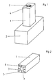
- Fig. 1 shows a holder 1 which is screwed to a workpiece 2.
- the holder 1 is a square with a central bore with countersink 3 for a screw 4.
- the holder 1 is provided on its lower surface, as shown in FIGS. 2 and 3, with contact surfaces 5, pressure edges on pressure prisms 6 and cutouts 7 between contact surfaces 5.
- the cross-shaped pressure prisms protrude the contact surfaces by between 0.1 and 3 mm.
- the recesses are at least 0.1 mm deep and close, based on the contact surfaces the material displaced by the pressure on the workpiece.
- the impression of the holder 1 on the workpiece 2 is shown in FIG. 4.
- the impressions 14 are arranged in a cross shape around the threaded bore 13.
- the contact surfaces can have 8 different shapes.
- the pressure edges on pressure prisms 9 can be arranged in several rows. In addition to pressure edges or instead of pressure edges, pressure points on pyramids 10, 15, cones 16 or balls 11 can also be provided.
- the holder depending on the size, can also be provided with several holes 3 for several screws.
- the cutouts 7 are correspondingly different.
- the holder according to the invention can accordingly be produced variably for any desired purpose.
Landscapes
- Engineering & Computer Science (AREA)
- Mechanical Engineering (AREA)
- General Engineering & Computer Science (AREA)
- Chemical & Material Sciences (AREA)
- Chemical Kinetics & Catalysis (AREA)
- Electrochemistry (AREA)
- Jigs For Machine Tools (AREA)
- Connection Of Plates (AREA)
- Pallets (AREA)
- Gripping Jigs, Holding Jigs, And Positioning Jigs (AREA)
- Forging (AREA)
- Laminated Bodies (AREA)
- Pressure Welding/Diffusion-Bonding (AREA)
Applications Claiming Priority (2)
| Application Number | Priority Date | Filing Date | Title |
|---|---|---|---|
| DE4024971A DE4024971A1 (de) | 1990-08-07 | 1990-08-07 | Halter fuer werkstuecke aus metall und anderen materialien wie kunststoffe oder holz |
| DE4024971 | 1990-08-07 |
Publications (3)
| Publication Number | Publication Date |
|---|---|
| EP0470410A2 true EP0470410A2 (fr) | 1992-02-12 |
| EP0470410A3 EP0470410A3 (en) | 1992-10-21 |
| EP0470410B1 EP0470410B1 (fr) | 1995-06-28 |
Family
ID=6411762
Family Applications (1)
| Application Number | Title | Priority Date | Filing Date |
|---|---|---|---|
| EP91112003A Expired - Lifetime EP0470410B1 (fr) | 1990-08-07 | 1991-07-18 | Réceptacle pour pièce, réalisé en métal, plastique ou en bois |
Country Status (4)
| Country | Link |
|---|---|
| EP (1) | EP0470410B1 (fr) |
| AT (1) | ATE124308T1 (fr) |
| DE (2) | DE4024971A1 (fr) |
| ES (1) | ES2073620T3 (fr) |
Families Citing this family (1)
| Publication number | Priority date | Publication date | Assignee | Title |
|---|---|---|---|---|
| TW481060U (en) | 2001-03-19 | 2002-03-21 | Mosel Vitelic Inc | Positioning jig for spraying and washing equipment |
Family Cites Families (11)
| Publication number | Priority date | Publication date | Assignee | Title |
|---|---|---|---|---|
| US3178780A (en) * | 1961-06-07 | 1965-04-20 | Fluor Corp | Structural joint connector |
| DE1197727B (de) * | 1961-06-21 | 1965-07-29 | Forkardt Paul Kg | Stirnmitnehmer fuer Drehbaenke |
| CH384980A (fr) * | 1962-08-25 | 1965-02-26 | Boillat S A | Dispositif de fixation et d'orientation d'une pièce sur une machine-outil |
| US4035093A (en) * | 1976-03-01 | 1977-07-12 | The Boeing Company | Bi-directional adjustable couplings |
| EP0111092B2 (fr) * | 1982-10-18 | 1992-11-25 | Erowa AG | Dispositif d'accouplement |
| CH670975A5 (en) * | 1986-05-16 | 1989-07-31 | Istema Ind Elektrotechnik Und | Electroerosion electrode with integral coupling surfaces - fitted directly to counter coupling of electroerosion machine |
| ATE69189T1 (de) * | 1986-06-02 | 1991-11-15 | Erowa Ag | Vorrichtung zum einspannen von nicht umlaufenden werkstuecken. |
| DE3625608A1 (de) * | 1986-07-29 | 1988-04-21 | 3R Management Ab | Spannvorrichtung fuer ein werkzeug an einer werkzeugmaschine, insbesondere einer senkerodiermaschine |
| KR920006653B1 (ko) * | 1986-10-03 | 1992-08-14 | 아사히 고오가꾸 고오교오 가부시끼가이샤 | 방전가공시스템 및 방전가공용 전극의 설치구 |
| EP0308908B1 (fr) * | 1987-09-24 | 1992-03-25 | Büchler B-SET AG | Méthode de manufacture d'un second article positionné très précisément par rapport à un premier article |
| DE8910889U1 (de) * | 1989-09-11 | 1990-01-04 | Ringwald, Thomas, 7208 Spaichingen | Befestigung von Elektroden in einem Elektrodenschaft |
-
1990
- 1990-08-07 DE DE4024971A patent/DE4024971A1/de active Granted
-
1991
- 1991-07-18 ES ES91112003T patent/ES2073620T3/es not_active Expired - Lifetime
- 1991-07-18 DE DE59105837T patent/DE59105837D1/de not_active Expired - Fee Related
- 1991-07-18 AT AT91112003T patent/ATE124308T1/de not_active IP Right Cessation
- 1991-07-18 EP EP91112003A patent/EP0470410B1/fr not_active Expired - Lifetime
Also Published As
| Publication number | Publication date |
|---|---|
| DE4024971C2 (fr) | 1993-04-08 |
| DE59105837D1 (de) | 1995-08-03 |
| ATE124308T1 (de) | 1995-07-15 |
| DE4024971A1 (de) | 1992-02-13 |
| ES2073620T3 (es) | 1995-08-16 |
| EP0470410B1 (fr) | 1995-06-28 |
| EP0470410A3 (en) | 1992-10-21 |
Similar Documents
| Publication | Publication Date | Title |
|---|---|---|
| DE2339873C2 (de) | Anordnung zum Einstellen und Befestigen eines ein Schneidplättchen tragenden Blocks in einer nutförmigen Aufnahme im Werkzeugkörper eines spanabhebenden Werkzeugs | |
| EP0147531B1 (fr) | Dispositif pour serrer des pièces à usiner | |
| DE69919032T2 (de) | Werkzeug und schneidkopf für spanabhebende bearbeitung | |
| EP0182290A2 (fr) | Tête de fraisage | |
| DE3733849C1 (de) | Maschinenschraubstock mit Kraftverstaerker | |
| DE828787C (de) | Schneidwerkzeug | |
| DE9107615U1 (de) | Zweischneidiges Gesenkwerkzeug zum Fräsen und Bohren | |
| CH649936A5 (de) | Vorrichtung zum abschraegen einer werkstueckkante. | |
| EP0217035A1 (fr) | Tête porte-lames | |
| EP0761382B1 (fr) | Dispositif à positionner des pièces dans des dispositifs de serrage | |
| EP0275923A2 (fr) | Dispositif de serrage de pièces | |
| DE3320693A1 (de) | Werkzeughalter fuer werkzeugmaschinen | |
| DE3730589A1 (de) | Entgrat- und anfaswerkzeug | |
| EP0263476A2 (fr) | Procédé d'alignement d'une palette sur une table d'une machine-outil et pièce d'alignement à cet effet | |
| EP0470410B1 (fr) | Réceptacle pour pièce, réalisé en métal, plastique ou en bois | |
| CH679463A5 (fr) | ||
| DE3001120A1 (de) | Bohrwerkzeug mit einem wendebohrmesser | |
| DE3401200A1 (de) | Bohr- und ausdrehwerkzeug | |
| DE9108863U1 (de) | Halter für Werkstücke aus Metall und anderen Materialien wie Kunststoffe oder Holz | |
| DE1217741B (de) | Spannabhebendes Werkzeug mit auswechselbarem Schneidkoerper | |
| DE8401019U1 (de) | Bohr- und Ausdrehwerkzeug | |
| DE2312077C3 (de) | Schneidwerkzeug mit mindestens einem in einer Aussparung des Halters auf einer Unterlageplatte angeordneten Schneideinsatz | |
| CH557210A (de) | Einstellgeraet an einem ausdrehwerkzeug. | |
| DE102005045751A1 (de) | Einstellwinkelverstellung | |
| WO1992003253A1 (fr) | Dispositif de serrage pour machines-outils |
Legal Events
| Date | Code | Title | Description |
|---|---|---|---|
| PUAI | Public reference made under article 153(3) epc to a published international application that has entered the european phase |
Free format text: ORIGINAL CODE: 0009012 |
|
| AK | Designated contracting states |
Kind code of ref document: A2 Designated state(s): AT CH DE ES FR GB IT LI NL SE |
|
| PUAL | Search report despatched |
Free format text: ORIGINAL CODE: 0009013 |
|
| AK | Designated contracting states |
Kind code of ref document: A3 Designated state(s): AT CH DE ES FR GB IT LI NL SE |
|
| 17P | Request for examination filed |
Effective date: 19930413 |
|
| 17Q | First examination report despatched |
Effective date: 19940330 |
|
| GRAA | (expected) grant |
Free format text: ORIGINAL CODE: 0009210 |
|
| AK | Designated contracting states |
Kind code of ref document: B1 Designated state(s): AT CH DE ES FR GB IT LI NL SE |
|
| REF | Corresponds to: |
Ref document number: 124308 Country of ref document: AT Date of ref document: 19950715 Kind code of ref document: T |
|
| REF | Corresponds to: |
Ref document number: 59105837 Country of ref document: DE Date of ref document: 19950803 |
|
| ET | Fr: translation filed | ||
| REG | Reference to a national code |
Ref country code: ES Ref legal event code: FG2A Ref document number: 2073620 Country of ref document: ES Kind code of ref document: T3 |
|
| ITF | It: translation for a ep patent filed | ||
| GBT | Gb: translation of ep patent filed (gb section 77(6)(a)/1977) |
Effective date: 19951002 |
|
| PLBE | No opposition filed within time limit |
Free format text: ORIGINAL CODE: 0009261 |
|
| STAA | Information on the status of an ep patent application or granted ep patent |
Free format text: STATUS: NO OPPOSITION FILED WITHIN TIME LIMIT |
|
| 26N | No opposition filed | ||
| REG | Reference to a national code |
Ref country code: GB Ref legal event code: IF02 |
|
| PGFP | Annual fee paid to national office [announced via postgrant information from national office to epo] |
Ref country code: GB Payment date: 20040707 Year of fee payment: 14 |
|
| PGFP | Annual fee paid to national office [announced via postgrant information from national office to epo] |
Ref country code: FR Payment date: 20040708 Year of fee payment: 14 Ref country code: AT Payment date: 20040708 Year of fee payment: 14 |
|
| PGFP | Annual fee paid to national office [announced via postgrant information from national office to epo] |
Ref country code: NL Payment date: 20040727 Year of fee payment: 14 |
|
| PGFP | Annual fee paid to national office [announced via postgrant information from national office to epo] |
Ref country code: ES Payment date: 20040818 Year of fee payment: 14 |
|
| PG25 | Lapsed in a contracting state [announced via postgrant information from national office to epo] |
Ref country code: AT Free format text: LAPSE BECAUSE OF NON-PAYMENT OF DUE FEES Effective date: 20050718 Ref country code: IT Free format text: LAPSE BECAUSE OF NON-PAYMENT OF DUE FEES Effective date: 20050718 |
|
| PG25 | Lapsed in a contracting state [announced via postgrant information from national office to epo] |
Ref country code: ES Free format text: LAPSE BECAUSE OF NON-PAYMENT OF DUE FEES Effective date: 20050719 |
|
| PG25 | Lapsed in a contracting state [announced via postgrant information from national office to epo] |
Ref country code: NL Free format text: LAPSE BECAUSE OF NON-PAYMENT OF DUE FEES Effective date: 20060201 |
|
| GBPC | Gb: european patent ceased through non-payment of renewal fee |
Effective date: 20050718 |
|
| PG25 | Lapsed in a contracting state [announced via postgrant information from national office to epo] |
Ref country code: FR Free format text: LAPSE BECAUSE OF NON-PAYMENT OF DUE FEES Effective date: 20060331 |
|
| NLV4 | Nl: lapsed or anulled due to non-payment of the annual fee |
Effective date: 20060201 |
|
| REG | Reference to a national code |
Ref country code: FR Ref legal event code: ST Effective date: 20060331 |
|
| PGFP | Annual fee paid to national office [announced via postgrant information from national office to epo] |
Ref country code: CH Payment date: 20060714 Year of fee payment: 16 |
|
| PGFP | Annual fee paid to national office [announced via postgrant information from national office to epo] |
Ref country code: DE Payment date: 20060927 Year of fee payment: 16 |
|
| REG | Reference to a national code |
Ref country code: ES Ref legal event code: FD2A Effective date: 20050719 |
|
| REG | Reference to a national code |
Ref country code: CH Ref legal event code: PL |
|
| EUG | Se: european patent has lapsed | ||
| PG25 | Lapsed in a contracting state [announced via postgrant information from national office to epo] |
Ref country code: CH Free format text: LAPSE BECAUSE OF NON-PAYMENT OF DUE FEES Effective date: 20070731 Ref country code: DE Free format text: LAPSE BECAUSE OF NON-PAYMENT OF DUE FEES Effective date: 20080201 Ref country code: LI Free format text: LAPSE BECAUSE OF NON-PAYMENT OF DUE FEES Effective date: 20070731 Ref country code: SE Free format text: LAPSE BECAUSE OF NON-PAYMENT OF DUE FEES Effective date: 20070719 |
|
| PGFP | Annual fee paid to national office [announced via postgrant information from national office to epo] |
Ref country code: SE Payment date: 20060713 Year of fee payment: 16 |