EP0470414A2 - Procédé de fabrication d'un laser à gaz à scellement étanche - Google Patents
Procédé de fabrication d'un laser à gaz à scellement étanche Download PDFInfo
- Publication number
- EP0470414A2 EP0470414A2 EP91112115A EP91112115A EP0470414A2 EP 0470414 A2 EP0470414 A2 EP 0470414A2 EP 91112115 A EP91112115 A EP 91112115A EP 91112115 A EP91112115 A EP 91112115A EP 0470414 A2 EP0470414 A2 EP 0470414A2
- Authority
- EP
- European Patent Office
- Prior art keywords
- solder
- pump
- lasers
- tubes
- laser
- Prior art date
- Legal status (The legal status is an assumption and is not a legal conclusion. Google has not performed a legal analysis and makes no representation as to the accuracy of the status listed.)
- Withdrawn
Links
Images
Classifications
-
- H—ELECTRICITY
- H01—ELECTRIC ELEMENTS
- H01J—ELECTRIC DISCHARGE TUBES OR DISCHARGE LAMPS
- H01J9/00—Apparatus or processes specially adapted for the manufacture, installation, removal, maintenance of electric discharge tubes, discharge lamps, or parts thereof; Recovery of material from discharge tubes or lamps
- H01J9/40—Closing vessels
-
- H—ELECTRICITY
- H01—ELECTRIC ELEMENTS
- H01S—DEVICES USING THE PROCESS OF LIGHT AMPLIFICATION BY STIMULATED EMISSION OF RADIATION [LASER] TO AMPLIFY OR GENERATE LIGHT; DEVICES USING STIMULATED EMISSION OF ELECTROMAGNETIC RADIATION IN WAVE RANGES OTHER THAN OPTICAL
- H01S3/00—Lasers, i.e. devices using stimulated emission of electromagnetic radiation in the infrared, visible or ultraviolet wave range
- H01S3/02—Constructional details
- H01S3/03—Constructional details of gas laser discharge tubes
Definitions
- the present invention relates to a method for producing a vacuum-sealed gas laser according to the preamble of claim 1.
- a gas laser sealed by such a method is known from Siemens prospect 1986/87 "For He-Ne laser technology: tubes, modules, power supplies" .
- the lasers shown there on the title page and, for example, in FIG. 1 have pump tubes which are squeezed off at their end and are therefore sealed in a vacuum-tight manner.
- pump stems which are formed from a tube and a reinforcement located at the end thereof and which have to be individually clamped on a pumping station in order to be able to carry out the process steps of evacuation, heating and filling.
- the object on which the present invention is based is to simplify the production process for such lasers.
- This object is achieved in lasers according to the preamble of claim 1 by the characterizing features of claim 1.
- a soft solder seal can be produced in the vacuum vessel and the subsequent squeezing and cold welding guarantees the high quality of the vacuum-tight connection required and tested by the customer.
- An advantageous embodiment of the method according to the invention consists in that the mirrors of the lasers are adjusted before the pump tubes are squeezed and that lasers which are recognized as not being gas-tight are made accessible for reworking by melting the soft solder closure. After squeezing and cold welding the tube, reworking and subsequent refilling of a laser is practically no longer possible.
- the end of the pump tube is advantageously flanged like a flange, a solder ring is placed on the end and a plug is inserted into the solder ring and the end, the solder ring being shaped such that at least one air gap remains free to the interior of the pump tube.
- This arrangement is used in a vacuum vessel, evacuated, heated and filled with laser gas and finally the temperature in the vacuum vessel is increased to the soldering temperature, so that under the influence of the force of gravity the plug sinks into the softening solder and closes the pump tube after cooling in a vacuum-tight manner.
- This embodiment requires little outlay on equipment, and can be carried out in the vacuum vessel which is present anyway.
- a method is suitable in which several lasers are placed in a holder in the vacuum vessel so that the pump tubes protrude downwards, in which a vessel with soft solder is arranged under the pump tubes, in which the soft solder is brought to the soldering temperature after the pumping, heating and filling, the holder is lowered until the ends of the pump tubes are immersed in the liquid soft solder and then raised again, and in which after the soft solder has solidified in the pump tubes, the lasers are removed from the vacuum vessel and the pump tubes are squeezed off .
- the temperature in the vacuum vessel is advantageously reduced during the time in which the pump tubes are immersed in the solder. As a result, the soft solder rises in a defined way into the pump tubes due to the gas pressure in the laser, which decreases with temperature.
- these are advantageously provided with a layer of silver / palladium or gold, at least in their end regions wetted by the soft solder.
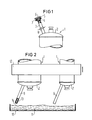
- FIGS. 1-10 show examples of arrangements of lasers according to the invention which, when used in a vacuum vessel, are suitable for carrying out the method according to the invention, schematically in a partially cut and broken view.
- FIG. 1 shows a laser 1 with an end cap 2 made of metal, with which a pump tube 3 is connected in a vacuum-tight manner.
- the end 4 of the pump tube 3 is widened like a flange.
- a solder ring 5 is placed on this end 4, which is bent in a wavy manner in the circumferential direction.
- a plug 6 is inserted, which extends into the pump tube 3 and is thereby secured against slipping.
- the solder ring 5 has a wavy shape in the circumferential direction, so that gaps 7 remain free, through which the laser can be evacuated and laser gas can be let in.
- the arrangement is heated to the soldering temperature, the solder ring 5 melts, the plug 6 sinks into the solder, and after a subsequent cooling, a vacuum-tight connection is formed in the end region of the pump tube.
- the plug 6 can be removed again from the pump tube by tilting the laser and heating the soldering point to the soldering temperature. This creates the possibility of reopening, reworking and reclosing the scrap that arises during production due to insufficient vacuum tightness.
- the pump tube is squeezed together at the pinch zone 8 in the direction of the arrow, cold-welded and separated. This ensures the well-known and recognized high long-term durability of the vacuum.
- Pump tubes 9 are attached to end caps 2 and can be designed as straight tubes.
- the tubes 9 do not dip into the solder 11.
- This arrangement is placed in a vacuum vessel, after pumping out, heating and filling the vacuum vessel with laser gas, the holder 12 is lowered in the direction of the arrow until the tubes 9 are immersed in the liquid solder 11, which is now at the soldering temperature.
- the solder 11 rises into the tubes 9, the holder 12 is raised again in the direction of the arrow, the solder solidifies and closes the pump tubes 9 in a vacuum-tight manner.
- the temperature of the laser is advantageously reduced while the tube 9 is immersed in the solder 11. This results in a reduction in pressure in the laser, the solder is pressed into the tubes.
- the tubes 9 have gold, silver or silver / palladium layers 14 on their inner walls in their end region.
- the silver / palladium layers can still be soldered well even after heat treatment in air (for example when baking out) and, on the other hand, do not dissolve in soft solder, so that no special requirements have to be made to guide the soldering process (time, temperature).
Landscapes
- Physics & Mathematics (AREA)
- Engineering & Computer Science (AREA)
- Electromagnetism (AREA)
- Plasma & Fusion (AREA)
- Optics & Photonics (AREA)
- Manufacturing & Machinery (AREA)
- Laser Beam Processing (AREA)
- Lasers (AREA)
Applications Claiming Priority (2)
| Application Number | Priority Date | Filing Date | Title |
|---|---|---|---|
| DE4025047 | 1990-08-07 | ||
| DE4025047 | 1990-08-07 |
Publications (2)
| Publication Number | Publication Date |
|---|---|
| EP0470414A2 true EP0470414A2 (fr) | 1992-02-12 |
| EP0470414A3 EP0470414A3 (en) | 1992-04-08 |
Family
ID=6411801
Family Applications (1)
| Application Number | Title | Priority Date | Filing Date |
|---|---|---|---|
| EP19910112115 Withdrawn EP0470414A3 (en) | 1990-08-07 | 1991-07-19 | Method of producing a vacuum-tight sealed gaslaser |
Country Status (3)
| Country | Link |
|---|---|
| US (1) | US5108330A (fr) |
| EP (1) | EP0470414A3 (fr) |
| JP (1) | JPH04255279A (fr) |
Cited By (1)
| Publication number | Priority date | Publication date | Assignee | Title |
|---|---|---|---|---|
| CN118225696A (zh) * | 2024-03-29 | 2024-06-21 | 深圳市诺安智能股份有限公司 | 一种用于激光气体探测器的参考气室及制备方法 |
Families Citing this family (3)
| Publication number | Priority date | Publication date | Assignee | Title |
|---|---|---|---|---|
| RU2273928C1 (ru) * | 2004-09-06 | 2006-04-10 | Открытое акционерное общество "Научно-исследовательский институт газоразрядных приборов "Плазма" (ОАО "Плазма") | Способ изготовления активного элемента газового лазера |
| KR101813662B1 (ko) * | 2011-10-05 | 2017-12-29 | 어플라이드 머티어리얼스, 인코포레이티드 | 레이저 프로세싱 시스템들 내의 입자 제어 |
| EP4375725A1 (fr) * | 2022-11-28 | 2024-05-29 | Alpine Quantum Technologies GmbH | Cavité optique sous vide |
Family Cites Families (9)
| Publication number | Priority date | Publication date | Assignee | Title |
|---|---|---|---|---|
| DE821235C (de) * | 1948-12-16 | 1951-11-15 | Siemens Ag | Verfahren zum vakuumdichten Verschliessen von Gefaessen |
| US3141225A (en) * | 1960-05-23 | 1964-07-21 | Gen Electric | Method of sealing a metal tubulation |
| US3550034A (en) * | 1969-02-20 | 1970-12-22 | Nasa | Repetitively-pulsed,wavelength-selective laser |
| JPS4939794A (fr) * | 1972-08-28 | 1974-04-13 | ||
| SE375201B (fr) * | 1974-02-27 | 1975-04-07 | Ericsson Telefon Ab L M | |
| US4009407A (en) * | 1974-07-30 | 1977-02-22 | Panel Technology, Inc. | Segmented electrode type gas discharge display panel with mercury giver means |
| DE2506707C2 (de) * | 1975-02-18 | 1977-03-10 | Siemens Ag | Gaslaser mit vakuumdichtem entladungskolben |
| US4081762A (en) * | 1975-02-18 | 1978-03-28 | Siemens Aktiengesellschaft | Gas laser with a laser capillary positioned in a discharge tube |
| US4827484A (en) * | 1987-10-14 | 1989-05-02 | Melles Griot San Marcos Company | Apparatus and method for suppressing diffraction rings in a laser |
-
1991
- 1991-07-19 EP EP19910112115 patent/EP0470414A3/de not_active Withdrawn
- 1991-07-26 US US07/736,644 patent/US5108330A/en not_active Expired - Fee Related
- 1991-08-02 JP JP3216165A patent/JPH04255279A/ja not_active Withdrawn
Cited By (1)
| Publication number | Priority date | Publication date | Assignee | Title |
|---|---|---|---|---|
| CN118225696A (zh) * | 2024-03-29 | 2024-06-21 | 深圳市诺安智能股份有限公司 | 一种用于激光气体探测器的参考气室及制备方法 |
Also Published As
| Publication number | Publication date |
|---|---|
| JPH04255279A (ja) | 1992-09-10 |
| US5108330A (en) | 1992-04-28 |
| EP0470414A3 (en) | 1992-04-08 |
Similar Documents
| Publication | Publication Date | Title |
|---|---|---|
| DE69112596T2 (de) | Verfahren zur Herstellung doppelwandiger isolierender metallischer Behälter. | |
| EP0356644B1 (fr) | Procédé de fabrication de guides d'ondes sur un substrat en verre par échange ionique | |
| DE2326614A1 (de) | Verfahren zum hermetischen abdichten eines behaelters, insbesondere des gehaeuses eines halbleiters, durch aufsetzen einer deckplatte und verfahren zum herstellen einer solchen deckplatte | |
| DE2953127C1 (de) | Verfahren zur Herstellung eines gekapselten gasgefuellten elektrischen Schalters | |
| DE2835904C2 (de) | Verwendung einer Baueinheit aus Elektrode und Zuleitung | |
| DE102006041782A1 (de) | Vakuumröhre und Verfahren zur Herstellung einer Vakuumröhre | |
| DE1098102B (de) | Verfahren zur Herstellung einer elektrischen Halbleitervorrichtung | |
| DE1519901A1 (de) | Verfahren zum tiegelfreien Zonenschmelzen eines kristallinen Stabes | |
| EP0470414A2 (fr) | Procédé de fabrication d'un laser à gaz à scellement étanche | |
| DE19512089C1 (de) | Verfahren zur Verbindung von umformbaren Blechbauteilen, vorzugsweise Feinblechen, durch Löten | |
| DE2611388A1 (de) | Verfahren zur abdichtung von brennstaeben fuer kernreaktoren | |
| DE1138486B (de) | Verfahren zum hermetischen Verschliessen eines Gehaeuses, das ein Halbleiter-Bauelement umschliesst | |
| DE69013595T2 (de) | Verfahren zur Herstellung einer gasverschmolzenen Entladungsröhre. | |
| DE2209868C3 (de) | Verfahren zur Herstellung einer elektrischen Metalldampfentladungslampe | |
| DE2101870A1 (de) | Metall Glas Keramik Abdichtung, ins besondere fur einen Kondensator, sowie Ver fahren zur Herstellung einer solchen Ab dichtung | |
| DE4041041A1 (de) | Verfahren zum elektrischen punktschweissen von metallischen filtrierelementen | |
| DE19504350C2 (de) | Verfahren zum Herstellen eines Kontakthöckers durch Umschmelzen einer Kontaktflächenmetallisierung | |
| DE19630134A1 (de) | Fügeverfahren für Elektronik- und Elektrotechnik-Baugruppen | |
| DE2121516A1 (de) | Verfahren zur Herstellung hermetisch verschlossener elektrischer Bauteile | |
| DE1028241B (de) | Verfahren zur Herstellung einer vakuumdichten Verbindung fuer elektrische Entladungsgefaesse od. dgl. | |
| DE2716975B2 (de) | Verfahren zum Verbinden von Gußeisenteilen oder Stahlteilen mit Gußeisenteilen | |
| DE2253826C (de) | Kaltpreßschweißbare Gehausebau teile und Verfahren zur Herstellung derselben | |
| DE2253826B1 (de) | Kaltpreßschweißbare Gehausebau teile und Verfahren zur Herstellung derselben | |
| DE3111311A1 (de) | Verfahren zur abdichtung von elektromechanischen bauelementen | |
| EP0457346A1 (fr) | Procédé pour le soudage par trempage de plaquettes de circuits imprimés |
Legal Events
| Date | Code | Title | Description |
|---|---|---|---|
| PUAI | Public reference made under article 153(3) epc to a published international application that has entered the european phase |
Free format text: ORIGINAL CODE: 0009012 |
|
| AK | Designated contracting states |
Kind code of ref document: A2 Designated state(s): DE FR GB IT |
|
| PUAL | Search report despatched |
Free format text: ORIGINAL CODE: 0009013 |
|
| AK | Designated contracting states |
Kind code of ref document: A3 Designated state(s): DE FR GB IT |
|
| 17P | Request for examination filed |
Effective date: 19920508 |
|
| 17Q | First examination report despatched |
Effective date: 19930629 |
|
| STAA | Information on the status of an ep patent application or granted ep patent |
Free format text: STATUS: THE APPLICATION IS DEEMED TO BE WITHDRAWN |
|
| 18D | Application deemed to be withdrawn |
Effective date: 19950201 |