EP0470418A2 - Trockner für Filmentwicklungsgeräte - Google Patents
Trockner für Filmentwicklungsgeräte Download PDFInfo
- Publication number
- EP0470418A2 EP0470418A2 EP91112186A EP91112186A EP0470418A2 EP 0470418 A2 EP0470418 A2 EP 0470418A2 EP 91112186 A EP91112186 A EP 91112186A EP 91112186 A EP91112186 A EP 91112186A EP 0470418 A2 EP0470418 A2 EP 0470418A2
- Authority
- EP
- European Patent Office
- Prior art keywords
- reflectors
- substrate
- dryer
- housing part
- radiators
- Prior art date
- Legal status (The legal status is an assumption and is not a legal conclusion. Google has not performed a legal analysis and makes no representation as to the accuracy of the status listed.)
- Granted
Links
Images

Classifications
-
- G—PHYSICS
- G03—PHOTOGRAPHY; CINEMATOGRAPHY; ANALOGOUS TECHNIQUES USING WAVES OTHER THAN OPTICAL WAVES; ELECTROGRAPHY; HOLOGRAPHY
- G03D—APPARATUS FOR PROCESSING EXPOSED PHOTOGRAPHIC MATERIALS; ACCESSORIES THEREFOR
- G03D15/00—Apparatus for treating processed material
- G03D15/02—Drying; Glazing
- G03D15/027—Drying of plates or prints
Definitions
- the invention relates to a method for drying a developed, moist layer support and a device for carrying out the method.
- a drying device in which only one pair of radiators with reflectors arranged behind them and behind each of them a blower (not shown) with a fresh air duct is provided.
- these fans remove the water vapor generated during drying.
- the fresh air supplied cools the transport rollers, thus avoiding undefined predrying of the substrates on the rollers, which is disadvantageous when the material is passed through again.
- guide surfaces that run towards one another are provided after the radiators for guiding the layer supports to the subsequent pair of rollers.
- DE-OS 23 23 725 shows a dryer in which a blower is arranged on each side of the guideway for the substrate.
- Each blower demands fresh air into a kind of pressure chamber, from which the air is directed onto the layer support via individual air sources. With each air source, cool fresh air is consequently brought onto the layer support, the sole purpose of which is to cool it and to remove the water vapor generated by the infrared rays. The actual drying takes place here exclusively by infrared radiation.
- powerful blowers with a large space requirement are required.
- the delivery rate of the blowers must be adapted to the number of air sources, including the number of infrared radiators.
- DE-OS 21 53 752 describes a pure convection dryer in which already warmed air is passed onto the substrate.
- the invention has for its object to provide a method for drying a developed, moist support and an apparatus for performing the method so that the efficiency of the dryer is improved and an adaptation to the application-dependent power requirement is made possible without great effort.
- the method according to the invention enables a modular dryer structure, in which only the number of emitters has to be adapted to the required dryer output without the blowers having to be adapted.
- cross-flow fans which are very small and have a low noise level, an extremely space-saving and inexpensive dryer arrangement can be realized together with the guide surfaces tapering obliquely from the fan to the web.
- the operation of the dryer is also less expensive than the prior art. Because the air is not drawn out of the system immediately after it has flowed through the space between the infrared radiator and the layer support, but is again mixed with the main air stream, the energy with which the air was heated by the radiator is not lost, but remains in the system.
- This combined radiation-convection drying has the further advantage that an uneven drying result between exposed (dark) and unexposed (light) areas, as in pure radiation drying, is at least greatly reduced. Since the heated air also draws a lot of moisture from the substrate, the different absorption capacity of dark and light areas of the substrate cannot have a strong effect on the infrared radiation.
- the proportion of convection can be increased still further.
- the reflectors which are normally made of very thin materials, from thick materials with a large heat capacity; on the other hand, a reflector can be removed at least on each side of the substrate, so that the corresponding radiator also acts on the main air stream and heats it. If all parts that are hit by radiation are also colored black, the efficiency increases further.
- the dryer can be controlled by a control system so that the heating takes place during the break times and during the heating phase of the baths in the developing device.
- the dryer is controlled so that it is put into operation during these times when the temperature in the exhaust air drops below a certain minimum and is stopped again when the temperature reaches a maximum. Regulation during the drying operation can also take place via the temperature of the exhaust air by controlling the output of the reflectorless radiators.
- the special design of the housing and the spotlight on one side of the web as a cover that can be opened like a cover enables good accessibility even to long dryer sections in the event of a malfunction or for service purposes.
- the design of the individual dryer elements as components that are identical to one another, i.e. from radiators with reflectors that are identical to one another, and fans and shaft parts that are identical to one another, also allows the installation of dryers of different outputs and lengths with a small number of components to be assembled and a low stock level. As with the known dryer, an even supply of fresh air and a uniform drying quality are achieved.
- the dryer arrangement according to the invention can be implemented both in a vertical and in a horizontal arrangement.
- the air flow of the blowers can be directed into a room of the dryer, from which it can be directed via ventilation hoses or shafts into suitable rooms, for example adjoining rooms or into the open, and does not burden the work area.
- FIGS. 1 and 2 denotes a carrier part or part of a housing, on which housing parts 2 and 3 of a dryer for developed, light-sensitive substrates are mounted.
- a developing machine, not shown, of any known type can also be mounted on this carrier part in the direction of the layer carrier transport before the dryer, so that it is permanently assigned to the dryer.
- the housing part 2 is fixedly mounted and in differently divided rooms, namely the room 2a for the input transport rollers 4, the room 2b for several infrared radiators 5 arranged one behind the other in the layer carrier transport direction with reflectors 6 arranged behind them and baffles 7 inclined between them towards the transport path and behind them Baffles 7 arranged transport rollers 8, the space 2c for a cross-flow blower 9, from which behind the reflectors 6 a baffle plate 10 which runs obliquely to the transport path runs as part of an air duct, and the space 2d into which the moist blower air flows after flowing through the dryer and can be directed through a hose 11 into the free or another space suitable for this, so that it does not burden the installation and work space for the developing machine and dryer.
- the spatial structure of the housing part 3 is arranged essentially symmetrically to that of the housing part 2 with respect to the layer carrier web, but is arranged such that it can be pivoted about the axis 12 from the housing part 2 and, of course, can be locked to the latter in the closed state.
- the emitters 5, reflectors 6, guide plates 7 and rollers 8 and the blower 9 in the housing part 2 are arranged in such a way that in the closed state of the housing part 3 they each have the same part in the housing part 2, a pair symmetrical to the layer carrier web form.
- the rooms 2a to 2d are drawn in the schematic drawings as continuous lines, as are the radiators, reflectors, rollers and fans which are not visible when the housing 2, 3 is closed.
- the housing and the built-in parts have openings across the width of the layer carrier web and sufficient spacings over the length of the layer carrier web that the air streams from the fans 9 can flow in via the rollers 8 and between the radiators 5 into the layer carrier web and further in their direction.
- the blowers 9 can be arranged at the lower end of the drying section and blow against the transport direction, as shown in FIGS. 1 and 2, or be mounted at the beginning of the drying section and blow in the layer carrier transport direction, as shown in FIG. 3.
- the housing part 3 has rooms 3b and 3c corresponding to rooms 2b and 2c.
- the rollers 8 of the roller pairs are all mounted in the fixed housing part 2, because this makes their drive easier.
- radiators 5, reflectors 6 and guide plates 7 and the fan 9 of the pivotable housing part 3 are mounted in this.
- projecting bearing tabs 2e, 3e are provided on both housing parts 2, 3, which are shaped and arranged in such a way that they engage in a tooth-like manner in the closed state of the dryer. For the sake of clarity, they are only numbered in Figure 1.
- FIG. 3 In contrast to Figures 1 and 2, in which a vertical dryer arrangement with three Radiator units 5, 6, 7 is shown, a dryer according to the invention is shown in FIG. 3 in a horizontal arrangement with only two radiator units. Parts having the same effect are numbered with the same reference numbers as in FIGS. 1 and 2.
- the blowers 9 are arranged at the dryer entrance, as already mentioned.
- the upper housing part 3 is the housing part which can be opened like a lid.
- the bearing tabs 2e, 3e are attached to the inner surfaces of the side housing walls, so that the dividing line between the two housing parts 2 and 3 is formed by a straight line.
- the air shafts 10 for the blowers 9 are formed here by housing inner walls running obliquely towards one another.
- radiators 5 The same components are used as radiators 5, reflectors 6, guide plates 7, rollers 8, so that, regardless of the size of the dryer and the number of its radiator pairs, only a small number of different components need to be kept in stock.
- the reflectors and baffles and their brackets are simple bent parts, the brackets 13, 14 only extending over a small part of the dryer width, so that they do not obstruct the radiation and air currents of the blowers 9. Openings 6a can be arranged in the reflectors 6, which do not noticeably interfere with their reflection effect, but also allow the blown air to pass through.
- the mode of operation of an exemplary embodiment according to the invention is to be described in FIG.
- the cross-flow blowers 9 are excellently suited for this drying process, since they deliver a uniform flow over the entire width of the substrate. Their operation is also very quiet, so that no special noise protection measures have to be taken.
- Cross-flow fans can only be used for the drying process described, since the fans do not have to generate high pressure here.
- an air delivery rate of 200 cbm / h is sufficient, regardless of the number of infrared emitters.
- a main air flow A is generated in the air shaft 10 by the fan 9.
- a partial air stream B branches off in front of the first radiator 5a, moves between the radiator 5a and the transport path for the film and combines again with the main air stream A.
- This partial air stream now acts in two ways. On the one hand, it removes the moisture caused by the action of infrared radiation between the radiator and the film, and on the other hand, the air sweeps over the film surface and absorbs further moisture.
- the partial air flow B is also heated by the radiator. That means that the
- Main air stream A is heated by mixing with the partial air stream B and its moisture content is increased.
- the partial air flow C already has a higher temperature than the partial air flow B, as a result of which the convection portion of the drying is increased compared to the radiation portion which has remained the same.
- the last partial air flow D has the highest temperature and thus also the highest convection component.
- the main air stream A after mixing with the partial air stream D, has a temperature of up to approx. 55 ° C and is still used for pre-drying the film in the form of pure convection drying.
- the radiator 5a is not equipped with a reflector.
- the radiation is therefore directed backwards and thus contributes to the heating of the main air stream A.
- the effect can be increased further if the oblique boundary wall of the air shaft 10 is colored black.
- the dryer is regulated via the control electronics 20. If the dryer output is too low, for example, the temperature in the outflowing air is measured by the temperature sensor 21. The control electronics then increase the power of the radiator 5a until the temperature in the exhaust air is in a certain range.
- the dryer output can be increased further in adaptation to ever larger film development speeds without the connected load having to be increased. To do this, the convection rate is increased again.
- storage masses are installed in the dryer, which during the so-called.
- Stand-by times i.e. the work breaks and the times in which the development baths are heated, are warmed up.
- the reflector 6b is shown in Figure 5, which is made of a thicker material than usual with a high storage capacity.
- This process is also controlled by the electronics 20.
- the dryer cools slowly and this drop in temperature is detected by the sensor 21.
- the electronics 20 then put the radiators 5 and the blowers 9 into operation.
- the heat storage heats up, e.g. the reflector 6b.
- the dryer is switched off again. In this way, the dryer is always ready for operation and can release the stored energy to the air flow as soon as heat is required.
Landscapes
- Physics & Mathematics (AREA)
- General Physics & Mathematics (AREA)
- Drying Of Solid Materials (AREA)
Abstract
Description
- Die Erfindung betrifft ein Verfahren zum Trocknen eines entwickelten, feuchten Schichtträgers und eine Vorrichtung zur Durchführung des Verfahrens.
- Durch die DE-PS 31 24 688 ist eine Trocknungseinrichtung bekannt geworden, in der nur ein Strahlerpaar mit dahinter angeordneten Reflektoren und hinter diesen je ein nicht dargestelltes Gebläse mit einem Frischluftkanal vorgesehen ist. Durch diese Gebläse wird einerseits der beim Trocknen entstehende Wasserdampf abgeführt. Zum andern werden durch die zugeführte Frischluft im Leerlauf die Transportwalzen gekühlt und somit eine beim erneuten Materialdurchlauf nachteilige, undefinierte Vortrocknung der Schichtträger an den Walzen vermieden. Dabei sind nach den Strahlern aufeinander zu laufende Führungsflächen zum Leiten der Schichtträger zum nachfolgenden Walzenpaar vorgesehen. Reicht bei dieser bekannten Trockneranordnung ein Strahlerpaar für eine schnelle, ausreichende Trocknung großer Schichtträgermengen nicht aus, so wäre es erforderlich, mehrere Strahlerpaare mit jeweils zwei Gebläsen und Frischluftkanälen hintereinander anzuordnen, was raumgreifend und wegen der großen Zahl von Gebläsen und Luftschächten kostenintensiv wäre.
- Die DE-OS 23 23 725 zeigt einen Trockner, in dem auf jeder Seite der Führungsbahn für den Schichtträger ein Gebläse angeordnet ist. Jedes Gebläse fordert Frischluft in eine Art Druckkammer, von der die Luft über einzelne Luftquellen auf den Schichtträger gerichtet wird. Mit jeder Luftquelle wird folglich kühle Frischluft auf den Schichtträger gebracht, die einzig die Aufgabe hat, diesen zu kühlen und den von den Infrarotstrahlen erzeugten Wasserdampf zu entfernen. Die eigentliche Trocknung erfolgt hier ausschließlich durch die Infrarotstrahlung. Um alle Luftquellen mit der entsprechenden Menge kühler Frischluft versorgen zu können, sind leistungsfähige Gebläse mit großem Platzbedarf erforderlich. Die Fördermenge der Gebläse muß an die Zahl der Luftquellen, also auch an die Zahl der Infrarotstrahler angepaßt werden.
- In der DE-OS 21 53 752 wird ein reiner Konvektionstrockner beschrieben, in dem bereits angewärmte Luft auf den Schichtträger geleitet wird.
- Der Erfindung liegt die Aufgabe zugrunde, ein Verfahren zum Trocknen eines entwickelten, feuchten Schichtträgers und eine Vorrichtung zur Durchführung des Verfahrens so auszugestalten, daß die Effizienz des Trockners verbessert und eine Anpassung an den von der Anwendung abhängigen Leistungsbedarf ohne großen Aufwand ermöglicht wird.
- Diese Aufgabe wird erfindungsgemäß gelöst durch die Merkmale des Verfahrensanspruchs 1 und des Vorrichtungsanspruchs 3. Weitere vorteilhafte Merkmale der Erfindung sind den Unteransprüchen entnehmbar.
- Das erfindungsgemäße Verfahren ermöglicht einen modularen Trockneraufbau, bei dem nur die Anzahl der Strahler an die erforderliche Trocknerleistung angepaßt werden muß, ohne daß eine Anpassung der Gebläse nötig ist. Durch den Einsatz von im Aufbau sehr kleinen und gerauscharm arbeitenden Querstromgebläsen läßt sich zusammen mit dem schräg vom Gebläse auf die Bahn zulaufenden Leitflächen eine äußerst raumsparende und kostengünstige Trockneranordnung verwirklichen.
- Kostengunstiger gegenüber dem Stand der Technik ist aber auch der Betrieb des Trockners. Dadurch, daß die Luft nicht sofort, wenn sie den Raum zwischen Infrarotstrahler und Schichtträger durchströmt hat, aus dem System abgezogen, sondern wieder mit dem Hauptluftstrom vermischt wird, geht auch die Energie, mit der die Luft durch den Strahler erwärmt wurde, nicht verloren, sondern bleibt dem System erhalten. Diese kombinierte Strahlungs-Konvektions-Trocknung hat den weiteren Vorteil, daß ein ungleichmäßiges Trocknungsergebnis zwischen belichteten (dunklen) und unbelichteten (hellen) Stellen, wie bei der reinen Strahlungstrocknung, zumindest stark verringert wird. Da auch die aufgeheizte Luft dem Schichtträger viel Feuchtigkeit entzieht, kann sich das unterschiedlich Absorptionsvermögen von dunklen und hellen Stellen des Schichtträgers für die Infrarotstrahlung nicht stark auswirken.
- Erfindungsgemäß kann der Konvektionsanteil aber noch weiter erhöht werden. Hierzu ist es einerseits möglich, die normalerweise aus sehr dünnen Materialien aufgebauten Reflektoren aus dickem Material mit großer Wärmekapazität zu fertigen; andererseits kann wenigstens auf jeder Seite des Schichtträgers ein Reflektor entfernt werden, so daß der entsprechende Strahler auch auf den Hauptluftstrom wirkt und diesen erwärmt. Werden zusätzlich alle Teile, auf die Strahlung auftrifft, schwarz eingefärbt, so erhöht sich der Wirkungsgrad weiter.
- Um den Konvektionsanteil auf die beschriebene Weise zu erhöhen, muß die Strahlerleistung nicht erhöht werden. Durch eine Steuerung kann der Trockner so geregelt werden, daß die Aufheizung in den Pausenzeiten und während der Aufheizphase der Bäder in der Entwicklungseinrichtung stattfindet. Der Trockner wird hierzu so gesteuert, daß er in diesen Zeiten dann in Betrieb gesetzt wird, wenn die Temperatur in der Abluft unter ein bestimmtes Minimum absinkt und wieder stillgesetzt wird, wenn die Temperatur ein Maximum erreicht. Eine Regelung während des Trocknungsbetriebes kann ebenfalls über die Temperatur der Abluft durch eine Leistungssteuerung der reflektorlosen Strahler erfolgen.
- Die besondere Ausgestaltung des Gehäuses und der Strahler auf einer Bahnseite als deckelartig aufklappbare Einheit ermöglicht eine gute Zugänglichkeit auch langer Trocknerstrecken im Störfall oder zu Servicezwecken. Die Ausbildung der einzelnen Trocknerelemente als jeweils untereinander gleiche Bauteile, also von untereinander gleichen Strahlern mit Reflektoren und untereinander gleichen Gebläsen und Schachtteilen erlaubt darüber hinaus die Montage von Trocknern unterschiedlicher Leistung und Baulänge mit einer geringen Zahl von zu montierenden Bauelementen und einer geringen Lagerhaltung. Dabei werden, ebenso wie beim bekannten Trockner, eine gleichmäßige Frischluftzufuhr und eine gleichmäßige Trocknungsqualität erreicht. Die erfindungsgemäße Trockneranordnung kann dabei sowohl in vertikaler als auch horizontaler Aufstellung verwirklicht werden. Schließlich kann der Luftstrom der Gebläse in einen Raum des Trockners geleitet werden, aus dem er über Abluftschläuche oder Schächte in hierfür geeignete Räume, z.B. Nebenräume oder in das Freie, geleitet werden kann und den Arbeitsraum nicht belastet.
- Die Erfindung wird anhand von Zeichnungen näher erläutert. Es zeigen
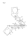
- Fig. 1 eine schematische Ansicht eines erfindungsgemäßen Trockners im in Reparatur- oder Schadensfällen geöffneten Zustand,
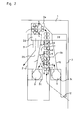
- Fig. 2 den Trockner nach Figur 1 im Gebrauchszustand,
- Fig. 3 eine horizontale Anordnung eines erfindungsgemäßen Trockners,
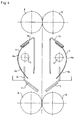
- Fig. 4 eine Strahlerbaueinheit eines erfindungsgemäßen Trockners und
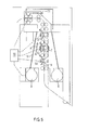
- Fig. 5 die Luftführung und die Temperatursteuerung eines nach dem erfindungsgemäßen Verfahren arbeitenden Trockners.
- In den Figuren 1 und 2 ist mit 1 ein Trägerteil oder ein Teil eines Gehäuses bezeichnet, an dem Gehäuseteile 2 und 3 eines Trockners für entwikkelte, lichtempfindliche Schichtträger gelagert sind. An diesem Trägerteil kann auch in Richtung des Schichtträgertransports vor dem Trockner eine nicht gezeigte Entwicklungsmaschine irgendeiner bekannten Bauart montiert sein, so daß sie dem Trockner fest zugeordnet ist. Das Gehäuseteil 2 ist dabei fest gelagert und in verschieden aufgeteilte Räume, nämlich den Raum 2a für die Eingangstransportwalzen 4, den Raum 2b für mehrere, hintereinander in Schichtträgertransportrichtung angeordnete Infrarotstrahler 5 mit dahinter angeordneten Reflektoren 6 und dazwischen zur Transportbahn hin geneigten Leitblechen 7 und hinter den Leitblechen 7 angeordneten Transportwalzen 8, den Raum 2c für ein Querstromgebläse 9, von welchem hinter den Reflektoren 6 ein zur Transportbahn zu schräg verlaufendes Leitblech 10 als Teil eines Luftschachtes verläuft, und den Raum 2d, in den die feuchte Gebläseluft nach Durchströmen durch den Trockner einmündet und durch einen nur angedeuteten Abfluß 11 über einen Schlauch in das freie oder einen anderen hierfür geeigneten Raum geleitet werden kann, so daß sie den Aufstell- und Arbeitsraum für Entwicklungsmaschine und Trockner nicht belastet.
- Der räumliche Aufbau des Gehäuseteils 3 ist zu der des Gehäuseteils 2 in Bezug auf die Schichtträgerbahn im wesentlichen symmetrisch angeordnet, jedoch um die Achse 12 vom Gehäuseteil 2 abschwenkbar angeordnet und natürlich an letzterem im geschlossenen Zustand verriegelbar.
- Außerdem sind bekannte und nicht gezeigte Verstrebungen mit Rasten vorgesehen, die ein Herunterfallen des Gehäuseteils 3 beim öffnen verhindern. In dem Gehäuseteil 3 sind den Strahlern 5, Reflektoren 6, Leitblechen 7 und Walzen 8 und dem Gebläse 9 im Gehäuseteil 2 gleichartige Teile so angeordnet, daß sie im geschlossenen Zustand des Gehäuseteils 3 jeweils mit dem gleichen Teil im Gehäuseteil 2 ein zur Schichtträgerbahn symmetrisches Paar bilden. Die Räume 2a bis 2d sind in den schematischen Zeichnungen als durchgehende Linien gezeichnet ebenso wie die bei geschlossenem Gehäuse 2, 3 nicht sichtbaren Strahler, Reflektoren, Walzen und Lüfter. Die Gehäuse und die Einbauteile weisen aber über die Breite der Schichtträgerbahn Öffnungen und über die Länge der Schichtträgerbahn genügend Abstände auf, daß die Luftströme von den Gebläsen 9 über die Walzen 8 und zwischen den Strahlern 5 in die Schichtträgerbahn und weiter in deren Richtung einströmen können. Dabei können die Gebläse 9 am unteren Ende der Trocknungsstrecke angeordnet sein und der Transportrichtung entgegenblasen, wie in den Figuren 1 und 2 gezeigt ist, oder am Anfang der Trocknungsstrecke gelagert sein und in Schichtträgertransportrichtung blasen, wie in Figur 3 gezeigt ist. Außerdem weist das Gehäuseteil 3 den Räumen 2b und 2c entsprechende Räume 3b und 3c auf.
- Gemäß den Figuren 1 und 2 sind die Walzen 8 der Walzenpaare alle im festen Gehäuseteil 2 gelagert, weil hierdurch deren Antrieb erleichtert wird.
- Dagegen sind die Strahler 5, Reflektoren 6 und Leitbleche 7 und das Gebläse 9 des schwenkbaren Gehäuseteils 3 in diesem gelagert. Hierzu sind an beiden Gehäuseteilen 2, 3 vorstehende Lagerlappen 2e, 3e vorgesehen, die so geformt und angeordnet sind, daß sie im geschlossenen Zustand des Trockners verzahnungsartig ineinandergreifen. Der übersichtlichkeit halber sind sie nur in Figur 1 beziffert.
- Im Gegensatz zu den Figuren 1 und 2, in denen eine vertikale Trockneranordnung mit drei Strahlerbaueinheiten 5, 6, 7 gezeigt ist, ist in Figur 3 ein erfindungsgemäßer Trockner in horizontaler Anordnung mit nur zwei Strahlerbaueinheiten gezeigt. Gleichwirkende Teile sind mit denselben Bezugsziffern wie in den Figuren 1 und 2 beziffert. Die Gebläse 9 sind dabei am Trocknereingang angeordnet, wie schon erwähnt. Der obere Gehäuseteil 3 ist dabei der deckelartig aufklappbare Gehäuseteil. Die Lagerlappen 2e, 3e sind an den Innenflächen der seitlichen Gehäusewandungen angebracht, so daß die Teilungslinie zwischen den beiden Gehäuseteilen 2 und 3 durch eine gerade Linie gebildet wird. Die Luftschächte 10 für die Gebläse 9 werden hierbei durch schräg aufeinander zu laufende Gehäuseinnenwände gebildet.
- Als Strahler 5, Reflektoren 6, Leitbleche 7, Walzen 8 werden jeweils untereinander gleiche Bauteile verwendet, so daß unabhängig von der Größe des Trockners und der Zahl seiner Strahlerpaare nur eine geringe Zahl von unterschiedlichen Bauteilen auf Lager gehalten zu werden brauchen. Wie aus Figur 4 entnehmbar ist, sind die Reflektoren und Leitbleche sowie ihre Halterungen einfache Biegeteile, wobei die Halterungen 13, 14 nur über einen geringen Teil der Trocknerbreite reichen, damit sie die Strahlungen und Luftströme der Gebläse 9 nicht behindern. In den Reflektoren 6 können Öffnungen 6a angeordnet sein, die ihre Reflexionswirkung nicht erkennbar stören, aber ebenfalls die Blasluft hindurchtreten lassen.
- In Figur 5 soll noch die Wirkungsweise eines erfindungsgemäßen Ausführungsbeispiels beschrieben werden. Die Querstromgebläse 9 sind ausgezeichnet für dieses Trocknungsverfahren geeignet, da sie eine gleichmäßige Strömung über die ganze Breite des Schichtträgers liefern. Ebenso ist ihr Betrieb sehr leise, so daß keine besonderen Schallschutzmaßnahmen getroffen werden müssen. Querstromgebläse können jedoch nur für das beschriebene Trocknungsverfahren eingesetzt werden, da die Gebläse hier keinen hohen Druck erzeugen müssen. Für das gezeigte Ausführungsbeispiel eines Trockners für Röntgenfilme ist - unabhängig von der Anzahl der Infrarotstrahler - eine Luftfördermenge von 200 cbm/h ausreichend.
- Durch das Gebläse 9 wird im Luftschacht 10 ein Hauptluftstrom A erzeugt. Vor dem ersten Strahler 5a zweigt ein Teilluftstrom B ab, bewegt sich zwischen dem Strahler 5a und der Transportbahn für den Film hindurch und vereinigt sich wieder mit dem Hauptluftstrom A. Dieser Teilluftstrom wirkt nun in zweierlei Hinsicht. Zum einen beseitigt er die Feuchtigkeit, die durch die Einwirkung der Infrarotstrahlung zwischen Strahler und Film entsteht, zum andern überstreicht die Luft die Filmoberfläche und nimmt dabei weitere Feuchtigkeit auf. Durch den Strahler wird der Teilluftstrom B aber auch erwärmt. Das bedeutet, daß auch der
- Hauptluftstrom A durch die Vermischung mit dem Teilluftstrom B erwärmt und sein Feuchtigkeitsgehalt gesteigert wird. Auf diese Weise hat bereits der Teilluftstrom C eine höhere Temperatur als der Teilluftstrom B, wodurch der Konvektionsanteil an der Trocknung gegenüber dem gleichgebliebenen Strahlungsanteil gesteigert wird. Die höchste Temperatur und damit auch den höchsten Konvektionsanteil weist der letzte Teilluftstrom D auf. Im Einlauf des Trockners hat der Hauptluftstrom A nach der Vermischung mit dem Teilluftstrom D eine Temperatur bis ca. 55°C und wird noch zur Vortrocknung des Films in Form von reiner Konvektionstrocknung genutzt.
- Um nun den Konvektionsanteil, der sich, wie bereits beschrieben, qualitätsverbessernd auswirkt, weiter zu steigern, ist der Strahler 5a nicht mit einem Reflektor ausgerüstet. Die Strahlung ist daher auch nach rückwärts gerichtet und trägt so zur Erwärmung des Hauptluftstroms A bei. Der Effekt kann noch gesteigert werden, wenn die schräge Begrenzungswand des Luftschachtes 10 schwarz eingefärbt ist.
- Eine Regelung des Trockners erfolgt über die Steuerelektronik 20. Ist die Trocknerleistung beispielsweise zu gering, so wird in der abströmenden Luft von dem Temperaturfühler 21 eine zu geringe Temperatur gemessen. Die Steuerelektronik erhöht dann die Leistung des Strahlers 5a, bis die Temperatur in der Abluft in einem bestimmten Bereich liegt.
- Bei dem gezeigten Ausführungsbeispiel kann die Trocknerleistung in Anpassung an immer größere Filmentwicklungsgeschwindigkeiten weiter erhöht werden, ohne daß die Anschlußleistung erhöht werden muß. Dazu wird nochmals der Konvektionsanteil erhöht. Hierzu werden in den Trockner Speichermassen eingebaut, die während der sogen.
- Stand-by-Zeiten, also, der Arbeitspausen und der Zeiten, in denen die Entwicklungsbäder aufgeheizt werden, erwärmt werden. Als Beispiel ist in Figur 5 der Reflektor 6b gezeigt, der aus einem dickeren Material als üblich mit hoher Speicherkapazität gefertigt ist. Gesteuert wird dieser Vorgang ebenfalls durch die Elektronik 20. Während des Stand-by-Betriebs kühlt der Trockner langsam ab und dieser Temperaturabfall wird von dem Fühler 21 detektiert. Die Elektronik 20 setzt daraufhin die Strahler 5 und die Gebläse 9 in Betrieb. Dabei heizen sich die Wärmespeicher, z.B. der Reflektor 6b, auf. Ab einer bestimmten Temperatur in der Abluft wird der Trockner wieder abgeschaltet. Auf diese Weise ist der Trockner immer betriebsbereit und kann, sobald Wärme benötigt wird, die gespeicherte Energie an den Luftstrom abgeben.
Claims (12)
Applications Claiming Priority (2)
| Application Number | Priority Date | Filing Date | Title |
|---|---|---|---|
| DE4024866 | 1990-08-04 | ||
| DE4024866 | 1990-08-04 |
Publications (3)
| Publication Number | Publication Date |
|---|---|
| EP0470418A2 true EP0470418A2 (de) | 1992-02-12 |
| EP0470418A3 EP0470418A3 (en) | 1992-08-26 |
| EP0470418B1 EP0470418B1 (de) | 1995-08-23 |
Family
ID=6411698
Family Applications (1)
| Application Number | Title | Priority Date | Filing Date |
|---|---|---|---|
| EP91112186A Expired - Lifetime EP0470418B1 (de) | 1990-08-04 | 1991-07-20 | Trockner für Filmentwicklungsgeräte |
Country Status (4)
| Country | Link |
|---|---|
| US (1) | US5228210A (de) |
| EP (1) | EP0470418B1 (de) |
| DE (1) | DE59106291D1 (de) |
| DK (1) | DK0470418T3 (de) |
Cited By (1)
| Publication number | Priority date | Publication date | Assignee | Title |
|---|---|---|---|---|
| EP0699958A1 (de) * | 1994-09-05 | 1996-03-06 | Agfa-Gevaert N.V. | Verfahren und Vorrichtung zur Behandlung von fotografischem Blattmaterial |
Families Citing this family (3)
| Publication number | Priority date | Publication date | Assignee | Title |
|---|---|---|---|---|
| US6401360B1 (en) | 2000-04-13 | 2002-06-11 | Eastman Kodak Company | Apparatus and method for drying photosensitive material using a radiant heat assembly |
| US6851545B1 (en) | 2004-03-23 | 2005-02-08 | Caddy Corporation | UVC conveyor belt system |
| DE102016123345B3 (de) * | 2016-12-02 | 2018-05-09 | Tilman Kraus | Vorrichtung zum Trocknen von Zahn- oder Knochenoberflächen |
Family Cites Families (12)
| Publication number | Priority date | Publication date | Assignee | Title |
|---|---|---|---|---|
| US2571815A (en) * | 1947-07-12 | 1951-10-16 | Remi A Benoit | Apparatus for and method of drying |
| DE1191690B (de) * | 1963-04-13 | 1965-04-22 | Internat Copying Machines Co M | Durchlauftrocknungsgeraet zum Trocknen fotografischer Schichttraeger |
| ZA711340B (en) * | 1970-03-19 | 1972-10-25 | Wiggins Teape Res Dev | Improvements in methods and apparatus for drying sheet material |
| IT965804B (it) * | 1972-05-10 | 1974-02-11 | Minnesota Mining & Mfg | Procedimento e dispositivo per la asciugatura rapida di pellicole fotografiche |
| US3973328A (en) * | 1972-05-26 | 1976-08-10 | Ilford Limited | Paper material dryer |
| US3826014A (en) * | 1973-03-19 | 1974-07-30 | Sun Chemical Corp | Shutter mechanism for radiation-curing lamp |
| IT1142448B (it) * | 1981-06-19 | 1986-10-08 | Minnesota Mining & Mfg | Dispositivo di asciugamento di pellicole fotografiche impregnate di acqua basato sulla cuombinazione di aria calda e raggi infrarossi emessi da sorgenti a potenza variabile |
| DE3334381A1 (de) * | 1983-09-23 | 1985-04-11 | Fleißner GmbH & Co, Maschinenfabrik, 6073 Egelsbach | Trockenschacht |
| US4594795A (en) * | 1984-10-23 | 1986-06-17 | Erik Stephansen | Air bearing support apparatus for drying a moving web |
| DE3522695C1 (de) * | 1985-06-25 | 1987-01-15 | Monforts Gmbh & Co A | Infrarottrockner |
| US4783908A (en) * | 1986-05-09 | 1988-11-15 | A. Monforts Gmbh & Co. | Infrared drying apparatus |
| US5097605A (en) * | 1989-03-31 | 1992-03-24 | Konica Corporation | Photosensitive material processing apparatus |
-
1991
- 1991-07-11 US US07/728,550 patent/US5228210A/en not_active Expired - Fee Related
- 1991-07-20 DE DE59106291T patent/DE59106291D1/de not_active Expired - Fee Related
- 1991-07-20 EP EP91112186A patent/EP0470418B1/de not_active Expired - Lifetime
- 1991-07-20 DK DK91112186.1T patent/DK0470418T3/da active
Cited By (1)
| Publication number | Priority date | Publication date | Assignee | Title |
|---|---|---|---|---|
| EP0699958A1 (de) * | 1994-09-05 | 1996-03-06 | Agfa-Gevaert N.V. | Verfahren und Vorrichtung zur Behandlung von fotografischem Blattmaterial |
Also Published As
| Publication number | Publication date |
|---|---|
| DK0470418T3 (da) | 1995-12-27 |
| EP0470418A3 (en) | 1992-08-26 |
| EP0470418B1 (de) | 1995-08-23 |
| US5228210A (en) | 1993-07-20 |
| DE59106291D1 (de) | 1995-09-28 |
Similar Documents
| Publication | Publication Date | Title |
|---|---|---|
| EP0341646B1 (de) | Verfahren und Vorrichtung zum Trocknen einer auf einem bewegten Trägermaterial aufgebrachten Flüssigkeitsschicht | |
| DE4228699C2 (de) | Vorrichtung zum chargenweisen Trocknen von Schnittholz | |
| DE2612734A1 (de) | Raumklimaanlage mit ventilator und waermetauscher | |
| DE3909175C3 (de) | Vorrichtung zur Behandlung von Monofilen | |
| DE3340489A1 (de) | Verfahren zum trocknen von schnittholz | |
| EP0070390B1 (de) | Vorrichtung zum Trocknen von band- oder blattförmigen, fotografischen Schichtträgern | |
| DE1192537B (de) | Vorrichtung zur Belueftung und/oder Beheizung von Fahrzeugkabinen | |
| EP0470418B1 (de) | Trockner für Filmentwicklungsgeräte | |
| EP0053269B1 (de) | Vorrichtung zur Wärmebehandlung von bahnförmigem Gut | |
| AT412484B (de) | Vorrichtung zum trocknen einer papierbahn | |
| DE4026107A1 (de) | Konvektions-trocken und/oder -fixiermaschine | |
| DE3334381A1 (de) | Trockenschacht | |
| EP0063642B1 (de) | Vorrichtung zur Heissluft-Trocknung von Textilgut | |
| DE60311028T2 (de) | Bildaufnahmegerät | |
| DE2842974A1 (de) | Vorrichtung fuer die klimatisierung von raeumen mit entsprechendem luftwechsel, insbesondere bei gefluegel-maststaellen | |
| DE19934487A1 (de) | Durchlauftrockner für Platten oder Bahnen | |
| DE2328978A1 (de) | Anordnung zum trocknen von band- oder blattfoermigem material | |
| DE3116836A1 (de) | Verfahren und vorrichtung zur heissluft-trocknung von textilgut | |
| DE60015739T2 (de) | Vorrichtung zur reinigung der trockenluft eines pulptrockners | |
| AT407797B (de) | Trocknungsanlage | |
| DE3026885C2 (de) | ||
| DE3123886A1 (de) | "verfahren und vorrichtung zur fuehrung der luft an einer mangel" | |
| DE1497394A1 (de) | Durchlauftrockengeraet fuer Blattfilme | |
| DE69510042T2 (de) | Verfahren und vorrichtung zum trocknen von holz | |
| DE2137377A1 (de) | Siebtrommel-trockeneinrichtung |
Legal Events
| Date | Code | Title | Description |
|---|---|---|---|
| PUAI | Public reference made under article 153(3) epc to a published international application that has entered the european phase |
Free format text: ORIGINAL CODE: 0009012 |
|
| AK | Designated contracting states |
Kind code of ref document: A2 Designated state(s): DE DK FR IT |
|
| PUAL | Search report despatched |
Free format text: ORIGINAL CODE: 0009013 |
|
| AK | Designated contracting states |
Kind code of ref document: A3 Designated state(s): DE DK FR IT |
|
| 17P | Request for examination filed |
Effective date: 19920925 |
|
| 17Q | First examination report despatched |
Effective date: 19941212 |
|
| GRAA | (expected) grant |
Free format text: ORIGINAL CODE: 0009210 |
|
| AK | Designated contracting states |
Kind code of ref document: B1 Designated state(s): DE DK FR IT |
|
| REF | Corresponds to: |
Ref document number: 59106291 Country of ref document: DE Date of ref document: 19950928 |
|
| ITF | It: translation for a ep patent filed | ||
| ET | Fr: translation filed | ||
| REG | Reference to a national code |
Ref country code: DK Ref legal event code: T3 |
|
| PLBE | No opposition filed within time limit |
Free format text: ORIGINAL CODE: 0009261 |
|
| STAA | Information on the status of an ep patent application or granted ep patent |
Free format text: STATUS: NO OPPOSITION FILED WITHIN TIME LIMIT |
|
| 26N | No opposition filed | ||
| PGFP | Annual fee paid to national office [announced via postgrant information from national office to epo] |
Ref country code: FR Payment date: 19970718 Year of fee payment: 7 |
|
| PG25 | Lapsed in a contracting state [announced via postgrant information from national office to epo] |
Ref country code: FR Free format text: LAPSE BECAUSE OF NON-PAYMENT OF DUE FEES Effective date: 19990331 |
|
| REG | Reference to a national code |
Ref country code: FR Ref legal event code: ST |
|
| PGFP | Annual fee paid to national office [announced via postgrant information from national office to epo] |
Ref country code: DE Payment date: 20030620 Year of fee payment: 13 |
|
| PGFP | Annual fee paid to national office [announced via postgrant information from national office to epo] |
Ref country code: DK Payment date: 20030711 Year of fee payment: 13 |
|
| PG25 | Lapsed in a contracting state [announced via postgrant information from national office to epo] |
Ref country code: DK Free format text: LAPSE BECAUSE OF NON-PAYMENT OF DUE FEES Effective date: 20040802 |
|
| PG25 | Lapsed in a contracting state [announced via postgrant information from national office to epo] |
Ref country code: DE Free format text: LAPSE BECAUSE OF NON-PAYMENT OF DUE FEES Effective date: 20050201 |
|
| REG | Reference to a national code |
Ref country code: DK Ref legal event code: EBP |
|
| PG25 | Lapsed in a contracting state [announced via postgrant information from national office to epo] |
Ref country code: IT Free format text: LAPSE BECAUSE OF NON-PAYMENT OF DUE FEES;WARNING: LAPSES OF ITALIAN PATENTS WITH EFFECTIVE DATE BEFORE 2007 MAY HAVE OCCURRED AT ANY TIME BEFORE 2007. THE CORRECT EFFECTIVE DATE MAY BE DIFFERENT FROM THE ONE RECORDED. Effective date: 20050720 |