EP0470472A2 - Dispositif d'enregistrement et de restitution d'un signal audio pour un appareil d'enregistrement et de restitution magnétique - Google Patents
Dispositif d'enregistrement et de restitution d'un signal audio pour un appareil d'enregistrement et de restitution magnétique Download PDFInfo
- Publication number
- EP0470472A2 EP0470472A2 EP91112691A EP91112691A EP0470472A2 EP 0470472 A2 EP0470472 A2 EP 0470472A2 EP 91112691 A EP91112691 A EP 91112691A EP 91112691 A EP91112691 A EP 91112691A EP 0470472 A2 EP0470472 A2 EP 0470472A2
- Authority
- EP
- European Patent Office
- Prior art keywords
- audio signals
- recording
- audio
- signals
- channels
- Prior art date
- Legal status (The legal status is an assumption and is not a legal conclusion. Google has not performed a legal analysis and makes no representation as to the accuracy of the status listed.)
- Withdrawn
Links
Images


Classifications
-
- G—PHYSICS
- G11—INFORMATION STORAGE
- G11B—INFORMATION STORAGE BASED ON RELATIVE MOVEMENT BETWEEN RECORD CARRIER AND TRANSDUCER
- G11B5/00—Recording by magnetisation or demagnetisation of a record carrier; Reproducing by magnetic means; Record carriers therefor
- G11B5/02—Recording, reproducing, or erasing methods; Read, write or erase circuits therefor
- G11B5/027—Analogue recording
-
- G—PHYSICS
- G11—INFORMATION STORAGE
- G11B—INFORMATION STORAGE BASED ON RELATIVE MOVEMENT BETWEEN RECORD CARRIER AND TRANSDUCER
- G11B27/00—Editing; Indexing; Addressing; Timing or synchronising; Monitoring; Measuring tape travel
- G11B27/02—Editing, e.g. varying the order of information signals recorded on, or reproduced from, record carriers
- G11B27/031—Electronic editing of digitised analogue information signals, e.g. audio or video signals
- G11B27/036—Insert-editing
-
- H—ELECTRICITY
- H04—ELECTRIC COMMUNICATION TECHNIQUE
- H04N—PICTORIAL COMMUNICATION, e.g. TELEVISION
- H04N5/00—Details of television systems
- H04N5/76—Television signal recording
- H04N5/765—Interface circuits between an apparatus for recording and another apparatus
- H04N5/775—Interface circuits between an apparatus for recording and another apparatus between a recording apparatus and a television receiver
-
- H—ELECTRICITY
- H04—ELECTRIC COMMUNICATION TECHNIQUE
- H04N—PICTORIAL COMMUNICATION, e.g. TELEVISION
- H04N5/00—Details of television systems
- H04N5/76—Television signal recording
- H04N5/91—Television signal processing therefor
- H04N5/92—Transformation of the television signal for recording, e.g. modulation, frequency changing; Inverse transformation for playback
- H04N5/9201—Transformation of the television signal for recording, e.g. modulation, frequency changing; Inverse transformation for playback involving the multiplexing of an additional signal and the video signal
- H04N5/9202—Transformation of the television signal for recording, e.g. modulation, frequency changing; Inverse transformation for playback involving the multiplexing of an additional signal and the video signal the additional signal being a sound signal
-
- H—ELECTRICITY
- H04—ELECTRIC COMMUNICATION TECHNIQUE
- H04N—PICTORIAL COMMUNICATION, e.g. TELEVISION
- H04N5/00—Details of television systems
- H04N5/76—Television signal recording
- H04N5/91—Television signal processing therefor
- H04N5/92—Transformation of the television signal for recording, e.g. modulation, frequency changing; Inverse transformation for playback
- H04N5/928—Transformation of the television signal for recording, e.g. modulation, frequency changing; Inverse transformation for playback the sound signal being pulse code modulated and recorded in time division multiplex with the modulated video signal
-
- G—PHYSICS
- G11—INFORMATION STORAGE
- G11B—INFORMATION STORAGE BASED ON RELATIVE MOVEMENT BETWEEN RECORD CARRIER AND TRANSDUCER
- G11B2220/00—Record carriers by type
- G11B2220/90—Tape-like record carriers
-
- G—PHYSICS
- G11—INFORMATION STORAGE
- G11B—INFORMATION STORAGE BASED ON RELATIVE MOVEMENT BETWEEN RECORD CARRIER AND TRANSDUCER
- G11B27/00—Editing; Indexing; Addressing; Timing or synchronising; Monitoring; Measuring tape travel
- G11B27/02—Editing, e.g. varying the order of information signals recorded on, or reproduced from, record carriers
- G11B27/031—Electronic editing of digitised analogue information signals, e.g. audio or video signals
- G11B27/032—Electronic editing of digitised analogue information signals, e.g. audio or video signals on tapes
Definitions
- This invention relates to a magnetic recording and playback apparatus operative to record and play back audio signals in multiple channels and a video signal, and particularly to a magnetic recording and playback apparatus capable of recording and playing back multiple audio signals in the high-definition television signal form.
- Magnetic tape recording and playback apparatus intended for home use i.e., rotary head, helical-scan video tape recorders (VTRs), have been designed to meet the NTSC standard television signal form (or PAL or SECAM signal form in Europe).
- VTRs helical-scan video tape recorders
- HDTV high definition television
- High-definition VTRs are divided into the analog recording system and digital recording system, as described in an article entitled “Special issue: Annual report on television, Section 4-2, HDTV (high vision)", in the publication of The Institute of Television Engineers of Japan, Vol. 42, No. 7, pp. 655-657, published in 1988.
- analog audio signals are recorded in two channels in the longitudinal direction of the magnetic tape
- digital recording high-definition VTR audio signals are recorded in eight channels in the longitudinal direction of the magnetic tape.
- NTSC-based composite digital VTR D 2 - type VTR
- digital audio signals are recorded in four channels in the rotary head scanning direction in the area different from that for the video signal track.
- This invention is intended to overcome the above-mentioned two prior art problems, and its prime object is to provide a magnetic recording and playback apparatus capable of reducing the quantity of magnetic tape used for audio signals so that long-term video recording is possible with a small-size cassette tape, while retaining the "after recording" function.
- the inventive apparatus operates to record audio signals based on weighting of four-channel HDTV audio signals depending on individual indispens- ability, and includes main signal recording and playback means for recording and reproducing main audio signals in two channels on the magnetic tape, and ancillary recording and playback means for recording and reproducing less indispensable, ancillary audio signals in two channels in an area different from the record area of the main signals, so that the ancillary signals can be rendered "after recording" at least when necessary.
- the audio signals of the four channels are labelled in a control signal, which is recorded in at least the ancillary signal record area, and the main signals can also be recorded by being superimposed on the video track when necessary.
- the two-channel main signals are recorded on a frequency division or time division basis by being superimposed on the video track when necessary, and the two-channel ancillary signals are recorded in an area different from that of the main signals on the magnetic tape.
- the ancillary signal area is an independent record area, such additional signals as narrations can be rendered "after recording", and the quantity of magnetic tape used to record audio signals can be reduced as compared with the conventional apparatus through superimposed recording of the main signals on the video track.
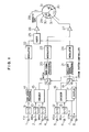
- Fig. 1 is a block diagram used to explain the recording operation of the apparatus.
- 1 is an input terminal for a video signal Vin
- 2 and 3 are input terminals for two-channel principal audio signals (main signals) AMin and BMin
- 4 is an input terminal for a main signal DMin in a digital form for transferring the main signals AMin and BMin in a serial manner over a signal line
- 5 and 6 are input terminals for two-channel ancillary audio signals ASin and BSin
- 7 is an input terminal for a control signal CTRLin which represents the types of the audio signals AMin, BMin, ASin and BSin
- 8 is an input terminal for an ancillary signal DSin in a digital form for transferring the ancillary audio signals ASin and BSin and the control signal CTRLin (these signals are called generically "ancillary signals”) in a serial manner over a signal line
- 9 through 13 are A/D converters for converting analog signals into digital signals
- 14 is a video signal processing circuit which operates in unison with a modulator 22 to implement the signal processing adapted to both
- 21 is an ancillary signal processing circuit which operates in unison with a modulator 24 to implement processing adapted to recording on the magnetic tape for the ancillary signal DSin or the signals produced by the encoder 16, 25 is an adder, 26 and 27 are recording amplifiers, 28 is a magnetic tape, 29 is a rotary drum, and 30 and 31 are rotary heads.
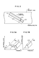
- Fig. 2 is a diagram showing record patterns on the magnetic tape 28.
- the video signal and the ancillary signals including the ASin, BSin and CTRLin signals are fed through the adder 25, recording amplifier 26 and rotary head 30, and recorded in a record area (video track) 101 and an ancillary signal record area (ancillary signal track) 103, respectively, on the magnetic tape 28.
- the area 101 is preferably a 180° record area, and therefore the wrap angle is set to be 180° + a so that the ancillary signals are recorded in the overlap section a.
- the ancillary signals are recorded in the area 103, and next the video signal is recorded in the area 101. Since signals are recorded in the areas (on a track) 101 and 103 with the same rotary head, they have the same azimuth angle.
- the main signals (including the AMin and BMin) are recorded digitally in a deep zone of the video track by being rendered frequency division and PCM coding, i.e., recorded by superimposition on the video track.
- the main signals are recorded by way of the recording amplifier 27 and rotary head 31 in a main signal record area which is located in a deep zone 102 of the video track 101 as shown in Fig. 2.
- these signals are recorded with different recording azimuths and different recording frequency bands as shown in the spectral diagrams of Figs. 3A and 3B.
- 3A is a frequency spectrum diagram for the rotary head 30, by which the ancillary signals are recorded to have a spectrum 203 for a duration from t a to t b in an ancillary signal record area 103 in Fig. 2, and thereafter the video signal is recorded to have a spectrum 201 for a duration from t a to t c in the area 101.
- Fig. 3B is a frequency spectrum diagram for the rotary head 31, by which the main signals are recorded to have a spectrum 202, which is a lower frequency band than 201, for a duration from t b to t c in a main signal record area 102 in a deep zone of the video track 101.
- a high frequency bias signal may be recorded in the area 102 when necessary.
- these ASin, BSin and CTRLin signals can be re-recorded arbitrarily by "after recording".
- the BSin and CTRLin records are read out with the rotary heads 30 in every revolution of the rotary head and stored together with a new record ASin in a buffer memory (not shown), and the contents of the buffer memory are recorded in the area 103 in each subsequent revolution of the head.
- the recording current to the rotary heads 31 is cut off.
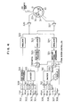
- 301-308 output terminals provided in correspondence to the input terminals of Fig. 1, e.g., Vout corresponds to Vin, and AMout and BMout correspond to AMin and BMin
- 309-313 are D/A converters for converting digital signals to analog signals
- 314 is a video signal processing circuit which operates in unison with a demodulation circuit 322 to restore the original video signal from the signal picked up by the rotary head 30 and fed through a pre-amplifier 326
- 320 is a main signal processing circuit which operates in unison with a demodulation circuit 323 to implement error correction and decoding for the signal picked up by the rotary head 31 and fed through a pre-amplifier 327 so that the same digital signal form as of DMin and DMout is restored
- 321 is an ancillary signal processing circuit which operates in unison with a demodulation circuit 324 to restore the original signal form
- 318 and 319 are switches operated by the command signal S
- 315 and 316 are decode
- the playback operation is as follows. Record signals from the rotary head 30 are partially processed by 326, 322, 314 and 309 to reproduce the video signal Vout on the output terminal 301, and remaining portions of the signals from the ancillary signal record area are processed by 326, 324, 321, 319, 316, 312 and 313 to reproduce the ancillary signals ASout, BSout and CTRLout (or DSout) on the output terminals 305-308, respectively.
- Record signals from the rotary head 31 retrieved from the deep zone of the video track are processed by 327, 323, 320, 318, 315, 310 and 311 to reproduce the main signals AMout, BMout (or DMout) on the output terminals 302, 303 and 304, respectively.
- the main signals are indispensable audio information (usually, AMin and BMin carry the left and right side sounds of stereo audio information, as will be mentioned later)
- a simplified high-definition VTR to be designed such that the overlap section (section of angle a) in Fig. 2 is absent, i.e., only two-channel main signals are recorded.
- the two-channel recording VTR has a minimal compatibility (for the two-channel main signals to achieve the conventional stereo audio function) with the four-channel fully equipped VTR.
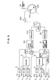
- PCM digital recording for the main signals on the video track based on time division will be described as the second embodiment of this invention with reference to the block diagram of Fig. 5 for the recording mode and the record pattern diagram of Fig. 6.
- the video signal Vin and the main signals are merged and rendered such digital signal processing as error correction and coding by 401, and thereafter modulated by 423, fed through an adder 425 and recording amplifier 426, and recorded by a rotary head 430 in a record area 501 shown in Fig. 6.
- the ancillary signals are recorded in an ancillary signal record area 503 in the same manner as the embodiment of Fig. 1. Both the video signal and main signals are rendered PCM digital recording which does not take up a 180° strip, and therefore a 180° strip is formed to include the area 503 as shown in Fig. 6.
- Fig. 7 shows a rotary drum based on this embodiment.
- a VHS-mode VTR operates with a recording tape on which two-channel longitudinal audio tracks are formed along one edge of the tape.
- the wrap angle is increased by as shown in Fig. 7 and the longitudinal audio tracks of VHS are made the overlap section for the ancillary audio area in Fig. 2.
- the details will be explained on the record pattern diagram of VHS in Fig. 8. Shown by the solid line in Fig. 8 are record patterns of VHS, which include longitudinal audio tracks 504 and 505, a video track 506, and a tracking control signal (CTL, which is different from the foregoing audio control signal) track 507.
- the unused longitudinal audio tracks 504 and 505 are taken by an overlap area 508 shown by the dashed line, and it is used for the ancillary audio signal area.
- the foregoing embodiments are designed to record the main signals in the video signal record area by superimposition, it is also possible to record the main signals in an area provided independently of the video signal area, as for the ancillary signals, if "after recording" is also needed for the main signals.
- the control signal is recorded in the ancillary signal record area in these embodiments, the signal may be recorded in the main signal record area or in both of the main and ancillary signal record areas when necessary. This scheme is particularly useful for a VTR which can record only two-channel main signals.
- Fig. 9 shows the connection for the audio system of the inventive VTR 602 with a high-definition television receiver 601 (incorporating a tuner and MUSE decoder on assumption of the MUSE broadcasting).
- the audio signals AMin, BMin, ASin and BSin received from the receiver 601 are of the left channel L, right channel R, center channel C and rear channel S, respectively, before selection.
- the control signal CTRLin is a serial or parallel digital signal (or it may be an analog signal which can express modes in terms of the signal level). These signals may have a form of base-band analog signal or a form of digital signals DMin and DSin for interfacing.
- the foregoing embodiments use "digital audio interface" stated in EIAJ standard CP-340 which is prevalent as the digital interface for CD players and the like.
- Fig. 10 shows the bit assignment of ancillary subframe based on the standard format of serial signal transfer.
- the 32-bit ancillary subframe consists of a 4-bit SYNC field, a 4-bit AUX field used for auxiliary information, a 20-bit PCM audio data field (used for the L channel or R channel), a parity flag bit V, a user bit U, a channel status bit C, and a parity bit P.
- CTRLin it is included in the ancillary signal in the embodiment of Fig. 1
- the AUX bits or user bit U in Fig. 10 is used.
- Fig. 11 is a diagram used to explain the playback operation through a pre-amplifier 701 and speakers 710-714 for the signals recorded in the inventive VTR 702 in the 3-1 mode (it uses the L,R,C and S channels as indicated by the CTAL signal) among the 3-1, 2-2, bilingual modes, etc. of the HDTV audio signal.
- the speakers 710-714 are placed on the left side, center, right side, rear left corner and rear right corner, respectively.
- Indicated by 703-707 are amplifiers which drive the respective speakers, and 708 is a controller which receives the CTRLout signal to produce the signal for controlling the switch 709.
- the four-channel audio signals recorded in the 3-1 mode are reproduced as AMout, BMout, ASout and BSout by the VTR 702 for the L, R, C and S channel sounds, respectively, and CTRLout includes information indicative of the 3-1 mode.
- the controller 708 identifies the signal transfer mode and operates on the switch 709 to make the connection shown by the dashed line so that the L, C, R, S and S channels are played back (formal 3-1 mode playback) on the speakers 710-714, respectively.
- the playback operation for the audio signals recorded in the 2-2 mode will be explained with reference to Fig. 12.
- This arrangement differs from Fig. 11 only in the state of the switch 709.
- the four-channel audio signals recorded in the 2-2 mode are reproduced as AMout, BMout, ASout and BSout by the VTR 702 for the L, R, LS (rear left corner) and RS (rear right corner) channel sounds, respectively, and the CTRLout signal includes information indicative of the 2-2 mode.
- the controller 708 identifies the mode and operates on the switch 709 to alter the connection as shown by the dashed line in Fig. 12, so that the speakers 710-714 produce the L, none, R, LS and RS channel sounds (2-2 mode playback). Records in the bilingual mode (e.g., the S channel is assigned to a foreign language) can be treated in the same manner.
- FIG. 13 Indicated by 802-807 are input terminals, and input signal conversion circuits 808 and 809 are provided in the front stage of the VTR 802.
- the following explanation is the case where the L, R, C, S and CTRLin signals in the 3-1 mode are applied to the input terminals 802-807.
- the L and R signals in the 3-1 mode are different slightly from the left and right channel signals of the conventional stereo audio system.
- the circuit 808 In response to the command signal S, the circuit 808 produces L' and R' from L, R, C and S, and these converted signals are recorded as AMin' and BMin' in the main signal area.
- the C and S signals are also used intact as the ASin' and BSin', and the CTRLin signal is added by information indicative of being converted by 809 (with information indicative of the 3-1 mode originally being retained), and these signals are recorded in the ancillary signal area.
- This embodiment is particularly useful for a VTR which can record only two-channel main signals.
- the two-channel recording VTR has its format retained common except for the ancillary signal area.
- the control signal is recorded preferably in both the main signal area and ancillary signal area.
- the playback operation yields the usual stereo effect (without rendering a feeling of center void).
- the compressed four-channel signal can be recorded in either main signal area or ancillary signal area through a signal line of the above-mentioned digital audio interface.
- the four-channel audio signal is entered to the VTR through the terminal 4 or 8 in Fig. 1.
- the unused record area (for two channels) can be used as an "after recording" area.
- this invention is designed to record four-channel HDTV audio signals by recording two channels of main signals and remaining two channels of ancillary signals in separate record areas, with the main signals being recorded by superimposition on the video track, whereby the quantity of magnetic tape used for the audio signals can be reduced.
- the separate ancillary signal area can be used for "after recording”. Recording of the control signal enables useful recording and playback of four-channel audio signals by discriminating the type of audio signals.
Landscapes
- Engineering & Computer Science (AREA)
- Multimedia (AREA)
- Signal Processing (AREA)
- Television Signal Processing For Recording (AREA)
- Signal Processing For Digital Recording And Reproducing (AREA)
- Recording Or Reproducing By Magnetic Means (AREA)
Applications Claiming Priority (2)
| Application Number | Priority Date | Filing Date | Title |
|---|---|---|---|
| JP2210360A JP2796412B2 (ja) | 1990-08-10 | 1990-08-10 | 磁気記録再生装置の音声信号記録再生装置 |
| JP210360/90 | 1990-08-10 |
Publications (2)
| Publication Number | Publication Date |
|---|---|
| EP0470472A2 true EP0470472A2 (fr) | 1992-02-12 |
| EP0470472A3 EP0470472A3 (en) | 1993-07-07 |
Family
ID=16588086
Family Applications (1)
| Application Number | Title | Priority Date | Filing Date |
|---|---|---|---|
| EP19910112691 Withdrawn EP0470472A3 (en) | 1990-08-10 | 1991-07-29 | Audio signal recording and playback apparatus of magnetic recording and playback apparatus |
Country Status (4)
| Country | Link |
|---|---|
| US (1) | US5323273A (fr) |
| EP (1) | EP0470472A3 (fr) |
| JP (1) | JP2796412B2 (fr) |
| KR (1) | KR950015002B1 (fr) |
Cited By (1)
| Publication number | Priority date | Publication date | Assignee | Title |
|---|---|---|---|---|
| WO1995022143A1 (fr) * | 1994-02-10 | 1995-08-17 | Philips Electronics N.V. | Ensemble d'enregistrement ou de reproduction d'un signal video numerique et d'un signal audio numerique correspondant |
Families Citing this family (5)
| Publication number | Priority date | Publication date | Assignee | Title |
|---|---|---|---|---|
| JP2766919B2 (ja) * | 1991-06-07 | 1998-06-18 | 三菱電機株式会社 | ディジタル信号記録再生装置、ディジタル信号記録装置、ディジタル信号再生装置 |
| KR950008753B1 (ko) * | 1993-02-05 | 1995-08-04 | 엘지전자주식회사 | 기록재생장치의 트랙킹신호 기록 재생 방법 및 회로 |
| JP3443938B2 (ja) * | 1994-03-31 | 2003-09-08 | ソニー株式会社 | ディジタル信号処理装置 |
| JP3912922B2 (ja) * | 1999-01-29 | 2007-05-09 | パイオニア株式会社 | 記録媒体と記録装置及び再生装置、記録方法及び再生方法 |
| US6925426B1 (en) | 2000-02-22 | 2005-08-02 | Board Of Trustees Operating Michigan State University | Process for high fidelity sound recording and reproduction of musical sound |
Family Cites Families (17)
| Publication number | Priority date | Publication date | Assignee | Title |
|---|---|---|---|---|
| GB2059135B (en) * | 1979-09-21 | 1983-11-30 | Rca Corp | Tape format having both video and audio information on same tracks and apparatus for recording and/or replaying same |
| DE3042269A1 (de) * | 1980-11-08 | 1982-06-09 | Basf Ag, 6700 Ludwigshafen | Verfahren und anordnungen zum veraendern der audioinformation in einem audio/video-aufzeichnungs/wiedergabesystem |
| JPS58128001A (ja) * | 1982-01-22 | 1983-07-30 | Sony Corp | 音声信号の再生装置 |
| JPS58166509A (ja) * | 1982-03-25 | 1983-10-01 | Sony Corp | 記録再生装置 |
| US4630134A (en) * | 1982-10-30 | 1986-12-16 | Pioneer Electronic Corporation | System for recording and reproducing multiplex information |
| JPS59127202A (ja) * | 1983-01-11 | 1984-07-23 | Victor Co Of Japan Ltd | 多重磁気記録装置及び多重磁気記録再生装置 |
| JPS6031707U (ja) * | 1983-08-09 | 1985-03-04 | 松下電器産業株式会社 | 磁気記録再生装置 |
| JPS6069879A (ja) * | 1983-09-26 | 1985-04-20 | Fuji Photo Film Co Ltd | ビデオテ−プレコ−ダ編集装置 |
| JPS60103506A (ja) * | 1983-11-11 | 1985-06-07 | Victor Co Of Japan Ltd | 信号記録再生装置 |
| US4758903A (en) * | 1984-11-22 | 1988-07-19 | Hitachi, Ltd. | Apparatus for recording and reproducing video signal and digital signal other than video signal |
| JP2580117B2 (ja) * | 1985-12-18 | 1997-02-12 | ソニー株式会社 | 再生装置における音場拡大装置 |
| JPS61287012A (ja) * | 1986-01-31 | 1986-12-17 | Canon Inc | 磁気記録装置 |
| JP2751201B2 (ja) * | 1988-04-19 | 1998-05-18 | ソニー株式会社 | データ伝送装置及び受信装置 |
| US4847698A (en) * | 1987-07-16 | 1989-07-11 | Actv, Inc. | Interactive television system for providing full motion synched compatible audio/visual displays |
| JPH01107373A (ja) * | 1987-10-21 | 1989-04-25 | Sony Corp | データ再生装置 |
| JPH01159801A (ja) * | 1987-12-16 | 1989-06-22 | Hitachi Ltd | 磁気録画再生装置 |
| US5043970A (en) * | 1988-01-06 | 1991-08-27 | Lucasarts Entertainment Company | Sound system with source material and surround timbre response correction, specified front and surround loudspeaker directionality, and multi-loudspeaker surround |
-
1990
- 1990-08-10 JP JP2210360A patent/JP2796412B2/ja not_active Expired - Lifetime
-
1991
- 1991-07-29 EP EP19910112691 patent/EP0470472A3/en not_active Withdrawn
- 1991-07-31 US US07/738,470 patent/US5323273A/en not_active Expired - Fee Related
- 1991-08-10 KR KR1019910013826A patent/KR950015002B1/ko not_active Expired - Fee Related
Cited By (2)
| Publication number | Priority date | Publication date | Assignee | Title |
|---|---|---|---|---|
| WO1995022143A1 (fr) * | 1994-02-10 | 1995-08-17 | Philips Electronics N.V. | Ensemble d'enregistrement ou de reproduction d'un signal video numerique et d'un signal audio numerique correspondant |
| US6289171B1 (en) | 1994-02-10 | 2001-09-11 | U. S. Philips Corporation | Arrangement for recording or reproducing a digital video signal and a corresponding digital audio signal |
Also Published As
| Publication number | Publication date |
|---|---|
| US5323273A (en) | 1994-06-21 |
| EP0470472A3 (en) | 1993-07-07 |
| JP2796412B2 (ja) | 1998-09-10 |
| KR920005067A (ko) | 1992-03-28 |
| JPH0495202A (ja) | 1992-03-27 |
| KR950015002B1 (ko) | 1995-12-21 |
Similar Documents
| Publication | Publication Date | Title |
|---|---|---|
| US4583132A (en) | Recording/reproducing apparatus for selectively processing monaural, stereo and bilingual signals | |
| CA2159693A1 (fr) | Methode d'enregistrement de signaux video numerique sur bande magnetique et methode de lecture connexe | |
| US5323273A (en) | Audio signal recording and playback apparatus of magnetic recording and playback apparatus | |
| US5790500A (en) | Apparatus for recording/reproducing converted four-channel audio signals | |
| JP3441748B2 (ja) | 音声信号処理装置及びその方法 | |
| US5499104A (en) | Apparatus for recording a video signal and stereophonic audio signals | |
| US5414523A (en) | Audio signal recording/reproducing apparatus for recording and reproducing high-definition television system audio signal of a plurality of channels | |
| US5687276A (en) | Magnetic recording and/or reproducing apparatus for detecting first and second attendant data indicative of a recording mode of associated digital information | |
| JP3006119B2 (ja) | 信号記録再生装置 | |
| JP2723657B2 (ja) | 磁気記録再生装置 | |
| JPS60111369A (ja) | 記録再生装置 | |
| JPS5821325B2 (ja) | ドロツプアウトホシヨウソウチオソナエタ タチヤンネルサイセイソウチ | |
| JP2768126B2 (ja) | 磁気記録再生装置 | |
| JPH0316137Y2 (fr) | ||
| KR0162212B1 (ko) | 음성신호편집기능을 갖는 하이-파이 브이티알 | |
| JP3371153B2 (ja) | ディジタル情報記録及び/又は再生装置 | |
| JPH0479071A (ja) | 音声信号記録装置 | |
| JPS60191469A (ja) | Vtr用アダプタ | |
| JPH01302503A (ja) | 回転ヘッド式磁気記録再生装置 | |
| JPS6059503A (ja) | 磁気記録再生装置 | |
| JPS61104369A (ja) | 磁気記録再生装置 | |
| JPH06121270A (ja) | 記録再生装置 | |
| JPS605477A (ja) | 磁気記録再生装置 | |
| JPH03280265A (ja) | 映像信号及び音声信号の記録再生装置 | |
| JPS58166507A (ja) | 信号再生装置 |
Legal Events
| Date | Code | Title | Description |
|---|---|---|---|
| PUAI | Public reference made under article 153(3) epc to a published international application that has entered the european phase |
Free format text: ORIGINAL CODE: 0009012 |
|
| AK | Designated contracting states |
Kind code of ref document: A2 Designated state(s): DE NL |
|
| PUAL | Search report despatched |
Free format text: ORIGINAL CODE: 0009013 |
|
| AK | Designated contracting states |
Kind code of ref document: A3 Designated state(s): DE NL |
|
| 17P | Request for examination filed |
Effective date: 19930528 |
|
| 17Q | First examination report despatched |
Effective date: 19950524 |
|
| STAA | Information on the status of an ep patent application or granted ep patent |
Free format text: STATUS: THE APPLICATION HAS BEEN WITHDRAWN |
|
| 18W | Application withdrawn |
Withdrawal date: 19960229 |