EP0470609B1 - Hohle Brücke für Lampe - Google Patents
Hohle Brücke für Lampe Download PDFInfo
- Publication number
- EP0470609B1 EP0470609B1 EP91113314A EP91113314A EP0470609B1 EP 0470609 B1 EP0470609 B1 EP 0470609B1 EP 91113314 A EP91113314 A EP 91113314A EP 91113314 A EP91113314 A EP 91113314A EP 0470609 B1 EP0470609 B1 EP 0470609B1
- Authority
- EP
- European Patent Office
- Prior art keywords
- bridge
- support
- melt
- support members
- heated
- Prior art date
- Legal status (The legal status is an assumption and is not a legal conclusion. Google has not performed a legal analysis and makes no representation as to the accuracy of the status listed.)
- Expired - Lifetime
Links
- 229910052751 metal Inorganic materials 0.000 claims description 8
- 239000002184 metal Substances 0.000 claims description 8
- 238000010438 heat treatment Methods 0.000 claims description 7
- 238000000034 method Methods 0.000 claims description 7
- 239000000463 material Substances 0.000 claims description 6
- 238000003825 pressing Methods 0.000 claims description 6
- 239000011810 insulating material Substances 0.000 claims description 5
- 238000004519 manufacturing process Methods 0.000 claims description 3
- 239000010453 quartz Substances 0.000 description 20
- VYPSYNLAJGMNEJ-UHFFFAOYSA-N silicon dioxide Inorganic materials O=[Si]=O VYPSYNLAJGMNEJ-UHFFFAOYSA-N 0.000 description 20
- 239000007787 solid Substances 0.000 description 17
- 238000010276 construction Methods 0.000 description 11
- 238000009826 distribution Methods 0.000 description 6
- 230000035882 stress Effects 0.000 description 6
- 239000011521 glass Substances 0.000 description 4
- VNWKTOKETHGBQD-UHFFFAOYSA-N methane Chemical compound C VNWKTOKETHGBQD-UHFFFAOYSA-N 0.000 description 4
- 229910052736 halogen Inorganic materials 0.000 description 3
- 229910052721 tungsten Inorganic materials 0.000 description 3
- 239000010937 tungsten Substances 0.000 description 3
- -1 tungsten halogen Chemical class 0.000 description 3
- 239000000155 melt Substances 0.000 description 2
- 238000000465 moulding Methods 0.000 description 2
- 239000003345 natural gas Substances 0.000 description 2
- 238000007789 sealing Methods 0.000 description 2
- UFHFLCQGNIYNRP-UHFFFAOYSA-N Hydrogen Chemical compound [H][H] UFHFLCQGNIYNRP-UHFFFAOYSA-N 0.000 description 1
- ZOKXTWBITQBERF-UHFFFAOYSA-N Molybdenum Chemical compound [Mo] ZOKXTWBITQBERF-UHFFFAOYSA-N 0.000 description 1
- 230000008901 benefit Effects 0.000 description 1
- 238000001816 cooling Methods 0.000 description 1
- 230000008878 coupling Effects 0.000 description 1
- 238000010168 coupling process Methods 0.000 description 1
- 238000005859 coupling reaction Methods 0.000 description 1
- 230000003247 decreasing effect Effects 0.000 description 1
- 230000008030 elimination Effects 0.000 description 1
- 238000003379 elimination reaction Methods 0.000 description 1
- 239000011888 foil Substances 0.000 description 1
- 239000007789 gas Substances 0.000 description 1
- 229910052739 hydrogen Inorganic materials 0.000 description 1
- 239000001257 hydrogen Substances 0.000 description 1
- 238000005286 illumination Methods 0.000 description 1
- 230000001771 impaired effect Effects 0.000 description 1
- 239000012212 insulator Substances 0.000 description 1
- 229910052750 molybdenum Inorganic materials 0.000 description 1
- 239000011733 molybdenum Substances 0.000 description 1
- 239000012811 non-conductive material Substances 0.000 description 1
- 230000008569 process Effects 0.000 description 1
- 230000009467 reduction Effects 0.000 description 1
- 230000007480 spreading Effects 0.000 description 1
- 238000003892 spreading Methods 0.000 description 1
- 230000008646 thermal stress Effects 0.000 description 1
Images


Classifications
-
- H—ELECTRICITY
- H01—ELECTRIC ELEMENTS
- H01K—ELECTRIC INCANDESCENT LAMPS
- H01K1/00—Details
- H01K1/18—Mountings or supports for the incandescent body
-
- H—ELECTRICITY
- H01—ELECTRIC ELEMENTS
- H01K—ELECTRIC INCANDESCENT LAMPS
- H01K3/00—Apparatus or processes adapted to the manufacture, installing, removal, or maintenance of incandescent lamps or parts thereof
- H01K3/08—Manufacture of mounts or stems
Definitions
- the invention relates to electric lamps and particularly to incandescent electric lamps. More particularly the invention is concerned with a tungsten halogen lamp with a tubular bridge support for the filament.
- a filament may be made larger, or longer. Larger diameter filaments are awkward to position, so in general filaments are made longer. The longer filament is then held in several places along its length for stable positioning.
- a common method for holding the lengthened filament is to fold the filament back and forth and hold the end of each fold with a support wire. The opposite ends of the support wires are then coupled to an insulator, usually made of quartz or glass, called a bridge. The bridge extends or bridges between two bridge supports, usually metal rods. The metal rods may or may not provide the electrical connections for the two ends of the filament.
- FIG. 1 shows a prior art solid rod bridge in cross section being heated by a flame.
- FIG. 2 shows a prior art solid rod bridge in cross section after being heated. Shading indicates the heat distribution. The bridge then moulds around the support rods and wires, and after cooling should remain permanently positioned against them. The moulding process results in a number of problems. Heating the entire mass of the bridge to pliability in the location where the moulding takes place cannot be done quickly, and uniformly. As shown in FIG.
- the heated side of the solid rod tends to be hotter and more pliable, while the opposite side, tends to be colder and less pliable during the pressing.
- Only a fraction of a solid quartz rod is in a fully plastic state when the coil support wires and side rods are pressed.
- a fair portion, indicated by the shaded area in FIG. 2, of the rod is cooler and less pliable.
- Only a limited portion of the bridge can then be spread up, down and around the support rod when the two are pressed together. A weak joint is then sometimes formed.
- the unmelted portion may also crack when pressed against the support rod.
- a thermal gradient exists across the bridge diameter, and residual stresses may be left in the bridge. The residual stresses may result in cracks on subsequent mechanical or thermal stress.
- the lamp frequently fails.
- Another problem is that a sufficient length of the bridge needs to wrap around the support rod when melted to a pliable state. If the bridge is too short, or insufficiently melted, the melted bridge fails to wrap around the support rod and permanently couple with the support rod. High rework rates and scrap factors are the result of cracked or broken bridges. Lamp costs then rise. There is then a need for a better bond between the bridge and bridge support in incandescent lamps.
- the present invention is characterised in that the bridge is made from a tube in its undeformed state.
- the bridge support members are formed from metal rods.
- the hollow bridge is formed from a tube of siliceous material positioned between the first bridge support member and the second bridge support member and melt fused to the first and second bridge support members.
- the present invention provides a method of making a bridge structure for an incandescent lamp comprising the steps of: providing two bridge support members being supported in a spaced relationship, providing a bridge of melt formable insulating material to extend across the two support members, heating the bridge to a plastic state, and pressing the bridge supports into the heated bridge to melt fuse the bridge to the bridge supports, characterised in that the bridge is deformed from a tubular shape during the heating and/or melt fusing stage.
- FIG. 1 shows a prior art solid rod bridge in cross section being heated by a flame.
- FIG. 2 shows a prior art solid rod bridge in cross section after being heated. Shading indicates the heat distribution.
- FIG. 3 shows a preferred embodiment of a hollow bridge in cross section being heated by flames.
- FIG. 4 shows a preferred embodiment of a hollow bridge in cross section after being heated. Shading indicates the heat distribution.
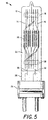
- FIG. 5 shows a cross section of a tungsten halogen lamp with a preferred embodiment of a hollow bridge.
- FIG. 6 shows a perspective view of a hollow bridge prior to pressing to bridge supports.
- FIG. 3 shows a preferred embodiment of a hollow bridge in cross section being heated by flames.
- FIG. 4 shows a preferred embodiment of a hollow bridge in cross section after being heated. Shading indicates the heat distribution.
- FIG. 5 shows a preferred embodiment of a tungsten halogen lamp 10 with a hollow bridge.
- the lamp 10 comprises an envelope 12, a first bridge support 14 formed from a metal rod, a second bridge support 16, a bridge 18 in the form of a tube, and a filament 20.
- the filament 20 may be electrically coupled between the first bridge support 14, and the second bridge support 16 to provide incandescent illumination on the application of electric power.
- the filament ends are electrically coupled to separate power leads.
- the envelope 12 may have any convenient form or material. Typically, envelopes are made of quartz or glass, and have either a bulbous or tubular forms.
- the envelope 12 includes an interior surface defining an enclosed volume 22. The enclosed volume 22 is sealed, and the envelope 12 has a base 24. The preferred base is separately formed and coupled to the envelope. Alternatively, a portion of the envelope may be heated and formed as a base.
- the first bridge support 14 may be formed from a metal rod coupled to the envelope 12. A nonconductive material may be used as the first bridge support 14, but the strength and toughness of metal is preferred for the first and second bridge supports 14, 16. A method sometimes used in coupling the envelope 12 to the bridge support is to capture the bridge support in the envelope seal 26 during sealing.
- the bridge support may penetrate the seal 26 area to be exposed on the exterior for direct electrical connection, or may be coupled through a sealing foil to an exterior lead for electrical connection.
- the variety of useful lamp seals is generally known in the art.
- the first bridge support 14 may be captured on the interior side of the seal 26 area and otherwise wholly contained in the envelope 12. The first bridge support 14 is then at least partially enclosed in the envelope 12, and not infrequently electrically coupled through the seal 26 area to receive electric power.
- the preferred lamp couples the bridge supports 14, 16 between two bridges 18, 28, and uses sturdy power leads 30, 32 to support one of the bridges 28.
- the second bridge support 16 may be similarly formed and supported in the envelope 12.
- the second bridge support 16 may be formed from a metal rod, at least partially enclosed in the envelope 12, and electrically coupled to receive electric power.
- the second bridge support 16 may function as the second electrical input to the lamp 10.
- the second bridge support 16 is captured between the first bridge 18, and the second bridge 28.
- the bridge 18 is formed as a hollow tube made of a melt formable insulating material.
- FIG. 6 shows a perspective view of a hollow bridge prior to pressing to bridge supports.
- the preferred bridge 18 is made of a hollow siliceous material such as quartz or glass.
- the tubular bridge 18 has an inside diameter 34, an outside diameter 36, a wall thickness 38 and a length 40.
- the inside diameter 34 is sufficiently large to reduce the thermal mass of the bridge 18.
- the inside diameter 34 is not so great that the tube has insufficient strength to hold the support wires.
- An inside diameter 34 of from one-third to about five-eighths of the outside diameter 36 is suggested. It has been found that an inside diameter 34 of one-half of the outside diameter 36 works well.
- the wall thickness in one example was about 1.0 millimeter, and the inside diameter was about 2.0 millimeters.
- the length 40 is sufficient to span the distance between the first bridge support 14, and second bridge support 16 with an additional amount of material to be adequately moulded around the bridge supports 14, 16.
- the use of circular cross sectional tubes for the tubular bridge 18 is a matter of convenience. Square or other shaped tubes may be used for the tubular bridge 18.
- the fires needed for heating the quartz tubes can be obtained from natural gas, while in the prior construction a hydrogen fire was required. More BTU's were needed to bring the solid quartz rods to a plastic state. Natural gas flames are easier to regulate, safer to operate, and cost less to operate.
- the preferred burners have two parallel rows of gas holes separated by about the diameter of the bridge and angled towards the bridge axis.
- the hollow tube used for the bridge had an inside diameter of 2.25 millimeter (0.0885 inch), and outside diameter of 4.25 millimeter (0.1675 inch), and an overall length of 22.0 millimeter (0.866 inch).
- the first and second supports rods were each made of molybdenum, with a diameter of 0.72 millimeter (0.0285 inch). The rods were separated by 18.5 millimeter (0.7285 inch).
- the burners had two parallel rows of holes separated by 2.03 millimeter (0.08 inch), and angled toward the bridge axis by about five degrees.
- tubular bridges substantially reduces the amount of broken bridges caused by a residual stress in the glass.
- the breakage rate was reduced from about 5.0 percent to about 0.2 percent.
- the tubular bridges also increase the mechanical strength of the construction by increasing the length up and down the side rods and coil supports covered by the quartz on average from 3.68 millimeter (0.145 inch) to 4.82 millimeter (0.190 inch). The increased covered length was an increase of 31 percent on average. Both improvements occurred while the weight of the bridge was decreased by 8.5 percent.
- Lamp shrinkage caused by broken bridges was reduced to almost zero when the hollow tube construction was used.
- the reduced breakage is thought to result from the elimination of residual stresses left in the quartz bridge.
- the smaller mass of the quartz tube allows a more even distribution of heat when the coil support wires, and support rods are pressed with the bridge. The even heat distribution then results in less internal stress.
- the coil supports and side rods were more broadly covered by the tubular bridge.
- the tubular bridges are then more securely bonded to the support rods, and no longer break free.
- Processing time for the bridge has been substantially reduced, since less time is needed to heat a tubular bridge to the necessary plastic state before pressing the support wires and support rods.
- the quartz heating time for a solid rod construction was about twelve seconds.
- the tubular bridge construction takes only about six seconds to heat.
- a bridge #4057-0083 for a C13-2000 watt-240 volt lamp NAED #546240 weights 4.120 grams when made with solid quartz and only 3.770 grams with quartz tubing construction, or an 8.5 percent reduction in weight.
- a further advantage of the hollow bridge construction is that the cost of making the bridges with the quartz tubing is much lower.
- the prior art construction used solid quartz bridges purchased separately. Meanwhile, the exhaust tubes cut from the lamps after being exhausted and tipped were being scrapped. The length of a discarded exhaust tube was approximately seventy-five percent of the original length of the exhaust tube, leaving a tubular piece about 47.63 millimeter (1.875 inch) . It was found that a tubular bridge may be made from the tubulation scrap using the new method, and the tubular bridge worked better than the solid bridge. The material cost of the tubular bridge to the manufacturer is then zero.
- the disclosed operating conditions, dimensions, configurations and embodiments are as examples only, and other suitable configurations and relations may be used to implement the invention.
Landscapes
- Engineering & Computer Science (AREA)
- Manufacturing & Machinery (AREA)
- Resistance Heating (AREA)
Claims (10)
- Brückenaufbau für ein Glühlampe mit zwei Brückenstützelementen (14, 16), die durch eine Brücke (18) in Abstand voneinander gehalten werden, wobei die Brücke aus einem Längenabschnitt schmelzformbaren isolierenden Materials hergestellt wird, das die beiden Stützelemente kreuzt und an dieselben angeschmolzen ist, dadurch gekennzeichnet, daß die Brücke (18) aus einem Rohr in seinem undeformierten Zustand hergestellt ist.
- Brückenaufbau nach Anspruch 1, bei welchem die Brückenstützelemente (14, 16) aus Metallstäben gebildet sind.
- Brückenaufbau nach Anspruch 1 oder 2, bei welchem die Brücke (18) aus einem siliziumhaltigen Material besteht.
- Brückenaufbau nach irgendeinem der Ansprüche 1, 2 oder 3, bei welchem die Brücke (18) aus einem zylindrischen Rohr in seinem undeformierten Zustand besteht, das einen inneren und einen äußeren Durchmesser (34, 36) aufweist.
- Brückenaufbau nach Anspruch 4, bei welchem der innere Durchmesser (34) der Brücke (18) in ihrem undeformierten Zustand kleiner ist als fünf Achtel des äußeren Durchmessers (36).
- Glühlampe mit einem Brückenaufbau nach irgendeinem der vorhergehenden Ansprüche.
- Verfahren zur Herstellung eines Brückenaufbaus nach irgendeinem der Ansprüche 1 bis 5 für eine Glühlampe, bestehend aus den folgenden Schritten:Zurverfügungsstellung von zwei Brückenstützelementen (14, 16), die in Abstand voneinander gehalten sind,Zurverfügungsstellung einer Brücke (18) aus durch Schmelzen formbarem isolierendem Material, die sich über die beiden Stützelemente erstreckt,Aufheizung der Brücke in einen plastischen Zustand und Eindrücken der Brückenstützen in die aufgeheizte Brücke, um die Brücke an den Brückenstützen anzuschmelzen,dadurch gekennzeichnet, daß die Brücke während des Zustands des Heizens und/oder Anschmelzens aus der rohrförmigen Gestalt deformiert wird.
- Verfahren nach Anspruch 7, bei welchem die Brücke (18) ausreichend aufgeheizt wird, um die aufgeheizte Seite gegen die gegenüberliegende Seite der Brücke kollabieren zu lassen.
- Verfahren nach Anspruch 7, bei welchem die Brückenstützen (14, 16) in die kollabierte Seite der Brücke (18) eingedrückt werden.
- Verfahren zur Herstellung einer Glühlampe mit einem Brückenaufbau, der nach irgendeinem der Verfahren nach Ansprüchen 7 bis 9 hergestellt ist.
Applications Claiming Priority (2)
| Application Number | Priority Date | Filing Date | Title |
|---|---|---|---|
| US07/572,652 US5159235A (en) | 1990-08-10 | 1990-08-10 | Hollow lamp bridge |
| US572652 | 1990-08-10 |
Publications (3)
| Publication Number | Publication Date |
|---|---|
| EP0470609A2 EP0470609A2 (de) | 1992-02-12 |
| EP0470609A3 EP0470609A3 (en) | 1992-09-23 |
| EP0470609B1 true EP0470609B1 (de) | 1996-12-11 |
Family
ID=24288779
Family Applications (1)
| Application Number | Title | Priority Date | Filing Date |
|---|---|---|---|
| EP91113314A Expired - Lifetime EP0470609B1 (de) | 1990-08-10 | 1991-08-07 | Hohle Brücke für Lampe |
Country Status (3)
| Country | Link |
|---|---|
| US (1) | US5159235A (de) |
| EP (1) | EP0470609B1 (de) |
| DE (1) | DE69123506T2 (de) |
Family Cites Families (5)
| Publication number | Priority date | Publication date | Assignee | Title |
|---|---|---|---|---|
| US3543962A (en) * | 1968-12-13 | 1970-12-01 | Sylvania Electric Prod | High wattage quartz halogen lamp |
| GB1189977A (en) * | 1969-03-25 | 1970-04-29 | Thorn Lighting Ltd | Improvements in Tungsten-Halogen Incandescent Lamps |
| US3785019A (en) * | 1972-01-12 | 1974-01-15 | Gte Sylvania Inc | Process for producing lamps |
| US4023060A (en) * | 1975-11-28 | 1977-05-10 | Gte Sylvania Incorporated | Ruggedized, high power tungsten-halogen lamp |
| US4766339A (en) * | 1987-03-16 | 1988-08-23 | Gte Products Corporation | Electric lamp with reinforced filament structure |
-
1990
- 1990-08-10 US US07/572,652 patent/US5159235A/en not_active Expired - Fee Related
-
1991
- 1991-08-07 DE DE69123506T patent/DE69123506T2/de not_active Expired - Lifetime
- 1991-08-07 EP EP91113314A patent/EP0470609B1/de not_active Expired - Lifetime
Also Published As
| Publication number | Publication date |
|---|---|
| US5159235A (en) | 1992-10-27 |
| EP0470609A3 (en) | 1992-09-23 |
| DE69123506T2 (de) | 1997-07-03 |
| DE69123506D1 (de) | 1997-01-23 |
| EP0470609A2 (de) | 1992-02-12 |
Similar Documents
| Publication | Publication Date | Title |
|---|---|---|
| US3798491A (en) | Rounded end halogen lamp with spiral exhaust tube and method of manufacutre | |
| JP2004119397A (ja) | 口金付高圧放電ランプ | |
| KR0123797B1 (ko) | 백열 램프의 필라멘트 지지구 | |
| US7002285B2 (en) | Discharge lamp with bulb fixture arrangement and method for manufacturing the same | |
| KR0156004B1 (ko) | 싱글엔드형 할로겐 백열램프 | |
| US4354137A (en) | Incandescent lamp having seal-anchored filament mount, and method of making such lamp | |
| US4469983A (en) | Electric lamp with an envelope seal designed as pinch seal, and a device and method for its manufacture | |
| US3668456A (en) | Lamp having improved press seal | |
| EP0160316B1 (de) | Einseitig gesockelte Hochintensitätsentladungslampe und Herstellung | |
| US5159235A (en) | Hollow lamp bridge | |
| US4409516A (en) | Rounded end halogen lamp with exhaust tube having different glass | |
| US4668204A (en) | Single-ended high intensity discharge lamp and manufacture | |
| US4203050A (en) | Gas discharge lamp and method | |
| US2675496A (en) | High-pressure discharge lamp and seal therefor | |
| EP0429256B1 (de) | Verbesserte Aufbauzuordnung für Doppelendlampe | |
| US3116992A (en) | Method of manufacture of lamp filament supports | |
| EP0651428B1 (de) | Glühlampe mit stossbeständigen Trägern | |
| JP2601337B2 (ja) | 白熱電球の製造方法 | |
| US6685525B1 (en) | Method for manufacturing an incandescent lamp | |
| US7391146B2 (en) | Halogen incandescent lamp | |
| CN107968029A (zh) | 一种无排气疤放电灯的制作工艺 | |
| US3249798A (en) | Fuse in lead-in of incandescent lamp filament | |
| JPS61104557A (ja) | 管球およびその製造方法 | |
| KR200196628Y1 (ko) | 핀치부를 가진 소다유리관 램프 | |
| JPH0315149A (ja) | 反射形ランプ・ユニット |
Legal Events
| Date | Code | Title | Description |
|---|---|---|---|
| PUAI | Public reference made under article 153(3) epc to a published international application that has entered the european phase |
Free format text: ORIGINAL CODE: 0009012 |
|
| 17P | Request for examination filed |
Effective date: 19910903 |
|
| AK | Designated contracting states |
Kind code of ref document: A2 Designated state(s): DE FR GB IT NL |
|
| PUAL | Search report despatched |
Free format text: ORIGINAL CODE: 0009013 |
|
| AK | Designated contracting states |
Kind code of ref document: A3 Designated state(s): DE FR GB IT NL |
|
| 17Q | First examination report despatched |
Effective date: 19940711 |
|
| GRAH | Despatch of communication of intention to grant a patent |
Free format text: ORIGINAL CODE: EPIDOS IGRA |
|
| GRAH | Despatch of communication of intention to grant a patent |
Free format text: ORIGINAL CODE: EPIDOS IGRA |
|
| GRAA | (expected) grant |
Free format text: ORIGINAL CODE: 0009210 |
|
| AK | Designated contracting states |
Kind code of ref document: B1 Designated state(s): DE FR GB IT NL |
|
| PG25 | Lapsed in a contracting state [announced via postgrant information from national office to epo] |
Ref country code: IT Free format text: LAPSE BECAUSE OF FAILURE TO SUBMIT A TRANSLATION OF THE DESCRIPTION OR TO PAY THE FEE WITHIN THE PRE;WARNING: LAPSES OF ITALIAN PATENTS WITH EFFECTIVE DATE BEFORE 2007 MAY HAVE OCCURRED AT ANY TIME BEFORE 2007. THE CORRECT EFFECTIVE DATE MAY BE DIFFERENT FROM THE ONE RECORDED.SCRIBED TIME-LIMIT Effective date: 19961211 |
|
| REF | Corresponds to: |
Ref document number: 69123506 Country of ref document: DE Date of ref document: 19970123 |
|
| ET | Fr: translation filed | ||
| PLBE | No opposition filed within time limit |
Free format text: ORIGINAL CODE: 0009261 |
|
| STAA | Information on the status of an ep patent application or granted ep patent |
Free format text: STATUS: NO OPPOSITION FILED WITHIN TIME LIMIT |
|
| 26N | No opposition filed | ||
| PGFP | Annual fee paid to national office [announced via postgrant information from national office to epo] |
Ref country code: DE Payment date: 19991028 Year of fee payment: 9 |
|
| PGFP | Annual fee paid to national office [announced via postgrant information from national office to epo] |
Ref country code: GB Payment date: 20000803 Year of fee payment: 10 |
|
| PGFP | Annual fee paid to national office [announced via postgrant information from national office to epo] |
Ref country code: FR Payment date: 20000823 Year of fee payment: 10 |
|
| PGFP | Annual fee paid to national office [announced via postgrant information from national office to epo] |
Ref country code: NL Payment date: 20000831 Year of fee payment: 10 |
|
| PG25 | Lapsed in a contracting state [announced via postgrant information from national office to epo] |
Ref country code: DE Free format text: LAPSE BECAUSE OF THE APPLICANT RENOUNCES Effective date: 20001021 |
|
| PG25 | Lapsed in a contracting state [announced via postgrant information from national office to epo] |
Ref country code: GB Free format text: LAPSE BECAUSE OF NON-PAYMENT OF DUE FEES Effective date: 20010807 |
|
| PG25 | Lapsed in a contracting state [announced via postgrant information from national office to epo] |
Ref country code: NL Free format text: LAPSE BECAUSE OF NON-PAYMENT OF DUE FEES Effective date: 20020301 |
|
| GBPC | Gb: european patent ceased through non-payment of renewal fee |
Effective date: 20010807 |
|
| PG25 | Lapsed in a contracting state [announced via postgrant information from national office to epo] |
Ref country code: FR Free format text: LAPSE BECAUSE OF NON-PAYMENT OF DUE FEES Effective date: 20020430 |
|
| NLV4 | Nl: lapsed or anulled due to non-payment of the annual fee |
Effective date: 20020301 |
|
| REG | Reference to a national code |
Ref country code: FR Ref legal event code: ST |