EP0470621A2 - Procédé de fabrication de corps moulés en carbure de silicium infiltré du silicium - Google Patents
Procédé de fabrication de corps moulés en carbure de silicium infiltré du silicium Download PDFInfo
- Publication number
- EP0470621A2 EP0470621A2 EP91113343A EP91113343A EP0470621A2 EP 0470621 A2 EP0470621 A2 EP 0470621A2 EP 91113343 A EP91113343 A EP 91113343A EP 91113343 A EP91113343 A EP 91113343A EP 0470621 A2 EP0470621 A2 EP 0470621A2
- Authority
- EP
- European Patent Office
- Prior art keywords
- silicon
- silicon carbide
- carrier
- walls
- inner walls
- Prior art date
- Legal status (The legal status is an assumption and is not a legal conclusion. Google has not performed a legal analysis and makes no representation as to the accuracy of the status listed.)
- Withdrawn
Links
Images


Classifications
-
- C—CHEMISTRY; METALLURGY
- C04—CEMENTS; CONCRETE; ARTIFICIAL STONE; CERAMICS; REFRACTORIES
- C04B—LIME, MAGNESIA; SLAG; CEMENTS; COMPOSITIONS THEREOF, e.g. MORTARS, CONCRETE OR LIKE BUILDING MATERIALS; ARTIFICIAL STONE; CERAMICS; REFRACTORIES; TREATMENT OF NATURAL STONE
- C04B35/00—Shaped ceramic products characterised by their composition; Ceramics compositions; Processing powders of inorganic compounds preparatory to the manufacturing of ceramic products
- C04B35/515—Shaped ceramic products characterised by their composition; Ceramics compositions; Processing powders of inorganic compounds preparatory to the manufacturing of ceramic products based on non-oxide ceramics
- C04B35/56—Shaped ceramic products characterised by their composition; Ceramics compositions; Processing powders of inorganic compounds preparatory to the manufacturing of ceramic products based on non-oxide ceramics based on carbides or oxycarbides
- C04B35/565—Shaped ceramic products characterised by their composition; Ceramics compositions; Processing powders of inorganic compounds preparatory to the manufacturing of ceramic products based on non-oxide ceramics based on carbides or oxycarbides based on silicon carbide
- C04B35/573—Shaped ceramic products characterised by their composition; Ceramics compositions; Processing powders of inorganic compounds preparatory to the manufacturing of ceramic products based on non-oxide ceramics based on carbides or oxycarbides based on silicon carbide obtained by reaction sintering or recrystallisation
Definitions
- the invention relates to a method for siliconizing porous shaped bodies made of silicon carbide / carbon with a flat outer surface using a porous, flat carrier made of silicon infiltrated silicon carbide, which has recesses.
- silicon carbide shaped bodies are infiltrated with silicon, zones with a particularly high silicon content, so-called siliconized sheets, are often formed, as well as components that are undersilicated. Both lead to committee.
- the silicon carbide / carbon molded body is infiltrated via a porous silicon carbide plate which is provided with a coating of boron nitride, silicon carbide and carbon. Below the silicon carbide plate and possibly to the side of it there is (before heating the furnace) piece of elemental silicon.
- plate-shaped SiSiC infiltration aids has disadvantages. When the silicon, which is located between the fuel plates and the silicon carbide plates used as infiltration aids, has melted, the plates sink due to the force of gravity through the (specifically lighter) silicon and displace it. Due to the surface tension, silicon mirrors of up to 5 mm in height can form on the fuel plate.
- the sinking of the SiSiC plates into the molten silicon increases the silicon level. This can lead to the components coming into direct contact with the molten silicon when the plates are too low. This leads to uneven infiltration and the occurrence of stress in the component, which is often manifested by the formation of cracks. The resulting cracks fill with silicon and are visible in the component as siliconized sheets. This effect could be prevented on the one hand by reducing the amount of silicon per fuel plate or by increasing the thickness of the silicon carbide plates. However, both options reduce the economics of the process.
- the described method using SiSiC plates is also used to siliconize blanks that have at least one flat contact surface.
- a process has now been found for the siliconization of porous shaped bodies made of silicon carbide / carbon, which have at least one flat outer surface, in which a mixture of silicon carbide powder, organic binder and optionally carbon is shaped into a green body, the binder of the green body in a non-oxidizing atmosphere is removed by coking at approx. 1000 ° C and the blank obtained is siliconized by the action of liquid silicon at temperatures of at least 1400 C, the blank obtained having a flat outer surface resting on a porous SiSiC carrier which with its the lower part is in contact with liquid silicon, and the arrangement of SiSiC carrier and the molded article obtained is cooled after the siliconization has been completed, characterized in that the support surface of the carrier is flat and has several recesses.
- the porous SiSiC carrier has the shape of a grate which, in addition to outer walls, also contains at least one inner wall, outer walls and inner walls ending at the same height at the top (that is, suitable for storing a body with a flat outer surface) and at least the outer walls are in contact with the liquid silicon.
- the carrier can also take the form of a container, ie be suitable below for holding liquid silicon. But it is also possible to put down the grate on a plate known per se, on which even lumpy silicon will later be melted. To increase the silicon flow, the inner walls can also be pulled down so far that they (like the outer walls) are in contact with the liquid silicon.
- the grate forming the storage surface preferably has a plurality of parallel inner walls. It is also possible for two systems of parallel inner walls to be present which intersect and are in particular arranged perpendicular to one another.
- the common contact area can be reduced in that the inner walls of the rust-shaped carrier have recesses on the upper edge.
- the recesses on the upper edge are preferably rectangular, so that the top of the inner walls takes the form of a crenellated wall. It is also possible to design the outer walls accordingly at the same time.
- the common contact area between the carrier and the siliconized blank placed thereon (and thus the difficulties in removing the blank after the siliconizing) can also be reduced by rounding off the wall ends of the grate.
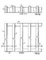
- FIGS. 2 to 5 show SiSiC carriers 11 in the form of a grate (1) which, in addition to outer walls 2, also contains at least one inner wall 3.
- the inner walls of Figures 2 to 4 show several parallel inner walls.
- the inner walls of Figure 3 show two systems of parallel inner walls (3 and 3 ') which are arranged perpendicular to each other.
- the inner walls and partially the outer walls have rectangular recesses (4) on the upper edge.
- the porous SiSiC carrier has the shape of a can, which stands on its side walls, the side walls being in contact with the liquid silicon at the bottom, the outer bottom of the can pointing upwards and provided with ribs projecting upwards is.
- the can is preferably circular and the ribs are arranged concentrically.
- the bottom can also be annular, i.e. have a concentrically arranged recess.
- the ribs should also be arranged concentrically here.
- the speed at which the silicon travels through the infiltration aid can be controlled by the amount and size of the pore diameter in the aid. This effect is already described (for the siliconization of the green body) in Special Ceramics 5, 1970 in connection with FIG. 6.
- a reduction in the pore diameter slows down the silicon flow, and an enlargement accelerates it.
- the size of the pore radii depends on the silicon carbide grains used in the manufacture of the kiln furniture. Coarse grain sizes (e.g. F 230) result in large pores, fine grain sizes (e.g. F 1200) result in small pores. Through a suitable selection of the silicon carbide grains, a large range of pore radius distributions can be set if necessary.
- FIG. 6 shows a SiSiC carrier 12 which has the shape of a circular can which stands on its circular side wall 2, the bottom of the can (5) being annular and having a concentrically arranged recess 6. Furthermore, the box has a plurality of ribs 7 on the upwardly facing outer bottom, which are also arranged concentrically. The side wall of the can (not shown) is in contact with the liquid silicon at the bottom.
- a blank 8 is deposited on the carrier, which has an approximately T-shaped cross section. The central part (10) of the blank is received by the central recess 6 of the carrier. The "bars" of the blank (8) with the T-shaped cross section are supported on the ribs 9.
Landscapes
- Chemical & Material Sciences (AREA)
- Engineering & Computer Science (AREA)
- Ceramic Engineering (AREA)
- Chemical Kinetics & Catalysis (AREA)
- Manufacturing & Machinery (AREA)
- Materials Engineering (AREA)
- Structural Engineering (AREA)
- Organic Chemistry (AREA)
- Ceramic Products (AREA)
Applications Claiming Priority (2)
| Application Number | Priority Date | Filing Date | Title |
|---|---|---|---|
| DE4025239 | 1990-08-09 | ||
| DE4025239A DE4025239C1 (fr) | 1990-08-09 | 1990-08-09 |
Publications (2)
| Publication Number | Publication Date |
|---|---|
| EP0470621A2 true EP0470621A2 (fr) | 1992-02-12 |
| EP0470621A3 EP0470621A3 (en) | 1992-08-12 |
Family
ID=6411925
Family Applications (1)
| Application Number | Title | Priority Date | Filing Date |
|---|---|---|---|
| EP19910113343 Withdrawn EP0470621A3 (en) | 1990-08-09 | 1991-08-08 | Method of making shaped silicon infiltrated silicon carbide bodies |
Country Status (6)
| Country | Link |
|---|---|
| EP (1) | EP0470621A3 (fr) |
| JP (1) | JPH072586A (fr) |
| DE (1) | DE4025239C1 (fr) |
| FI (1) | FI913756A7 (fr) |
| IE (1) | IE912808A1 (fr) |
| NO (1) | NO913096L (fr) |
Cited By (2)
| Publication number | Priority date | Publication date | Assignee | Title |
|---|---|---|---|---|
| US20080145293A1 (en) * | 2006-12-18 | 2008-06-19 | John Carberry | Ceramic Material Product and Method of Manufacture |
| US8603616B1 (en) | 2007-09-27 | 2013-12-10 | Schott Corporation | Lightweight transparent armor window |
Families Citing this family (6)
| Publication number | Priority date | Publication date | Assignee | Title |
|---|---|---|---|---|
| AT406238B (de) * | 1995-07-07 | 2000-03-27 | Electrovac | Formkörper aus mmc mit modulartigem aufbau |
| DE19856597B4 (de) * | 1998-10-14 | 2004-07-08 | Industrieanlagen-Betriebsgesellschaft Mbh | Schutzpanzerung |
| US7759276B2 (en) | 2004-07-23 | 2010-07-20 | Helsa-Automotive Gmbh & Co. Kg | Adsorptive formed body having an inorganic amorphous supporting structure, and process for the production thereof |
| EP1741687B1 (fr) | 2005-07-05 | 2011-10-12 | MANN+HUMMEL Innenraumfilter GmbH & Co. KG | Corps formé céramique poreux contenant ß-SiC et son procédé de préparation. |
| WO2007003428A1 (fr) | 2005-07-05 | 2007-01-11 | Helsa-Automotive Gmbh & Co. Kg | Corps moule ceramique contenant du $g(b)-sic poreux et presentant un revetement en oxyde d'aluminium et procede pour le produire |
| EP1741685B1 (fr) | 2005-07-05 | 2014-04-30 | MANN+HUMMEL Innenraumfilter GmbH & Co. KG | Corps formé céramique poreux contenant beta-SiC et son procédé de préparation. |
Family Cites Families (11)
| Publication number | Priority date | Publication date | Assignee | Title |
|---|---|---|---|---|
| BE794185A (fr) * | 1972-01-20 | 1973-07-18 | Norton Co | Nitrure de silicium haute densite |
| JPS523647B2 (fr) * | 1972-10-24 | 1977-01-29 | ||
| GB2010913B (en) * | 1977-12-23 | 1982-06-23 | Fiat Spa | Process for sintering silicon nitride compacts |
| CA1092793A (fr) * | 1978-07-03 | 1981-01-06 | Wendel G. Brown | Procede d'obtention de formes au carbure de silicone |
| US4264547A (en) * | 1978-11-08 | 1981-04-28 | Battelle Memorial Institute | Silicon nitride-based sintering composition |
| US4511525A (en) * | 1981-11-26 | 1985-04-16 | Tokyo Shibaura Denki Kabushiki Kaisha | Process for producing sintered silicon nitride-base body |
| DE3367764D1 (en) * | 1983-07-29 | 1987-01-08 | Hoechst Ceram Tec Ag | Method of making silicon-infiltrated reaction-bonded silicom carbide bodies |
| JPS63303867A (ja) * | 1987-01-12 | 1988-12-12 | Ngk Insulators Ltd | 窒化珪素セラミックス部品の製造法 |
| DE3719606A1 (de) * | 1987-06-12 | 1988-12-22 | Hoechst Ceram Tec Ag | Verfahren zur silicierung von poroesen formkoerpern aus siliciumcarbid oder siliciumcarbid/kohlenstoff |
| DK212988A (da) * | 1988-04-26 | 1989-10-20 | Brg Mechatronikai Vallalat | Koblingsindretning isaer til drift af magnetbaandsakslen paa magnetbaandsoptage- og afspilleapparater |
| JP2719942B2 (ja) * | 1988-12-03 | 1998-02-25 | 日本特殊陶業株式会社 | 窒化珪素焼結体及びその製造方法 |
-
1990
- 1990-08-09 DE DE4025239A patent/DE4025239C1/de not_active Expired - Fee Related
-
1991
- 1991-08-07 FI FI913756A patent/FI913756A7/fi unknown
- 1991-08-08 JP JP3199408A patent/JPH072586A/ja active Pending
- 1991-08-08 NO NO91913096A patent/NO913096L/no unknown
- 1991-08-08 EP EP19910113343 patent/EP0470621A3/de not_active Withdrawn
- 1991-08-08 IE IE280891A patent/IE912808A1/en unknown
Cited By (3)
| Publication number | Priority date | Publication date | Assignee | Title |
|---|---|---|---|---|
| US20080145293A1 (en) * | 2006-12-18 | 2008-06-19 | John Carberry | Ceramic Material Product and Method of Manufacture |
| US8262981B2 (en) * | 2006-12-18 | 2012-09-11 | Schott Corporation | Ceramic material product and method of manufacture |
| US8603616B1 (en) | 2007-09-27 | 2013-12-10 | Schott Corporation | Lightweight transparent armor window |
Also Published As
| Publication number | Publication date |
|---|---|
| FI913756L (fi) | 1992-02-10 |
| FI913756A0 (fi) | 1991-08-07 |
| NO913096D0 (no) | 1991-08-08 |
| FI913756A7 (fi) | 1992-02-10 |
| DE4025239C1 (fr) | 1991-12-19 |
| NO913096L (no) | 1992-02-10 |
| JPH072586A (ja) | 1995-01-06 |
| IE912808A1 (en) | 1992-02-12 |
| EP0470621A3 (en) | 1992-08-12 |
Similar Documents
| Publication | Publication Date | Title |
|---|---|---|
| DE3248103C1 (de) | Tiegel zum Ziehen von Einkristallen | |
| DE69715057T2 (de) | Polykristalliner Diamantverbundkörper | |
| DE69520527T2 (de) | Werkzeugeinsatz aus Schleifmaterial | |
| DE69713758T2 (de) | Bandgegossener siliciumcarbid-ersatzwafer | |
| DE60013535T2 (de) | Anordung zur ladung von zu wärmebehandelnden werkstücken | |
| DE4025239C1 (fr) | ||
| DE102009037293A1 (de) | Verbesserter Werkstückträger, Verfahren zu seiner Herstellung und dessen Verwendung | |
| EP0294850B1 (fr) | Procédé de silicisation des corps moulés de carbure de silicium/carbone | |
| EP1333013B1 (fr) | Matériaux d'insertion résistant à l'usure et de haute pureté et son procédé de fabrication | |
| DE50002898C5 (de) | Feuerfester keramischer Gasspülstein | |
| DE3907500C1 (en) | Gas bubble brick with directed porosity and method for its manufacture | |
| DE102011087507A1 (de) | Teilweise fertiggepresste / fertiggesinterte Wendeschneidplatte | |
| DE4025238C1 (fr) | ||
| DE202009010938U1 (de) | Verbesserter Werkstückträger | |
| EP0470622B1 (fr) | Procédé de fabrication de corps moulés en carbure de silicium infiltré du silicium | |
| EP0373354B1 (fr) | Procédé de production de corps moulés céramiques réfractaires | |
| DE102006031583A1 (de) | Verfahren zur Herstellung von Carbidkeramik-Bauteilen, Vorkörperverbund zur Herstellung von Carbidkeramik-Bauteilen und Carbidkeramik-Bauteilverbund | |
| CH664378A5 (de) | Verfahren zum einschmelzen einer metallischen oberflaechenschicht auf einem werkstueck. | |
| DE4026127C2 (de) | Verfahren zum Herstellen eines drucklos gesinterten Produktes | |
| DE29906393U1 (de) | Kassette | |
| EP0927863B1 (fr) | Superstructure céramique de chariot de four pour des produits crus en céramique | |
| DE29802626U1 (de) | Anlage zum Brennen von Dachziegeln auf flachliegenden Brennunterlagen sowie solche Brennunterlage | |
| EP1104982B1 (fr) | Pot a fleurs constitue d'un non tisse a fibres embrouillees et son procede de production | |
| DE20305182U1 (de) | Brennguttragevorrichtung | |
| EP0558869A1 (fr) | Objet comportant une surface abrasive et procédé pour sa fabrication |
Legal Events
| Date | Code | Title | Description |
|---|---|---|---|
| PUAI | Public reference made under article 153(3) epc to a published international application that has entered the european phase |
Free format text: ORIGINAL CODE: 0009012 |
|
| AK | Designated contracting states |
Kind code of ref document: A2 Designated state(s): AT BE CH DE DK ES FR GB IT LI LU NL SE |
|
| PUAL | Search report despatched |
Free format text: ORIGINAL CODE: 0009013 |
|
| AK | Designated contracting states |
Kind code of ref document: A3 Designated state(s): AT BE CH DE DK ES FR GB IT LI LU NL SE |
|
| 17P | Request for examination filed |
Effective date: 19930128 |
|
| 17Q | First examination report despatched |
Effective date: 19940421 |
|
| STAA | Information on the status of an ep patent application or granted ep patent |
Free format text: STATUS: THE APPLICATION HAS BEEN WITHDRAWN |
|
| 18W | Application withdrawn |
Withdrawal date: 19940816 |