EP0470657B1 - Procédé de commande de freinage à antiblocage à commande de relâchement pas à pas - Google Patents
Procédé de commande de freinage à antiblocage à commande de relâchement pas à pas Download PDFInfo
- Publication number
- EP0470657B1 EP0470657B1 EP91201873A EP91201873A EP0470657B1 EP 0470657 B1 EP0470657 B1 EP 0470657B1 EP 91201873 A EP91201873 A EP 91201873A EP 91201873 A EP91201873 A EP 91201873A EP 0470657 B1 EP0470657 B1 EP 0470657B1
- Authority
- EP
- European Patent Office
- Prior art keywords
- wheel
- brake
- motor
- release
- incipient
- Prior art date
- Legal status (The legal status is an assumption and is not a legal conclusion. Google has not performed a legal analysis and makes no representation as to the accuracy of the status listed.)
- Expired - Lifetime
Links
- 238000000034 method Methods 0.000 title claims description 20
- 238000011084 recovery Methods 0.000 claims description 42
- 230000001133 acceleration Effects 0.000 claims description 23
- 230000004044 response Effects 0.000 claims description 12
- 230000006870 function Effects 0.000 description 22
- 230000000694 effects Effects 0.000 description 11
- 239000012530 fluid Substances 0.000 description 6
- 238000010586 diagram Methods 0.000 description 4
- 230000007423 decrease Effects 0.000 description 3
- 230000003247 decreasing effect Effects 0.000 description 3
- 238000013459 approach Methods 0.000 description 1
- 238000004891 communication Methods 0.000 description 1
- 238000004590 computer program Methods 0.000 description 1
- 230000001419 dependent effect Effects 0.000 description 1
- 238000001514 detection method Methods 0.000 description 1
Images


Classifications
-
- B—PERFORMING OPERATIONS; TRANSPORTING
- B60—VEHICLES IN GENERAL
- B60T—VEHICLE BRAKE CONTROL SYSTEMS OR PARTS THEREOF; BRAKE CONTROL SYSTEMS OR PARTS THEREOF, IN GENERAL; ARRANGEMENT OF BRAKING ELEMENTS ON VEHICLES IN GENERAL; PORTABLE DEVICES FOR PREVENTING UNWANTED MOVEMENT OF VEHICLES; VEHICLE MODIFICATIONS TO FACILITATE COOLING OF BRAKES
- B60T8/00—Arrangements for adjusting wheel-braking force to meet varying vehicular or ground-surface conditions, e.g. limiting or varying distribution of braking force
- B60T8/32—Arrangements for adjusting wheel-braking force to meet varying vehicular or ground-surface conditions, e.g. limiting or varying distribution of braking force responsive to a speed condition, e.g. acceleration or deceleration
- B60T8/34—Arrangements for adjusting wheel-braking force to meet varying vehicular or ground-surface conditions, e.g. limiting or varying distribution of braking force responsive to a speed condition, e.g. acceleration or deceleration having a fluid pressure regulator responsive to a speed condition
- B60T8/42—Arrangements for adjusting wheel-braking force to meet varying vehicular or ground-surface conditions, e.g. limiting or varying distribution of braking force responsive to a speed condition, e.g. acceleration or deceleration having a fluid pressure regulator responsive to a speed condition having expanding chambers for controlling pressure, i.e. closed systems
- B60T8/4208—Debooster systems
- B60T8/4266—Debooster systems having an electro-mechanically actuated expansion unit, e.g. solenoid, electric motor, piezo stack
-
- B—PERFORMING OPERATIONS; TRANSPORTING
- B60—VEHICLES IN GENERAL
- B60T—VEHICLE BRAKE CONTROL SYSTEMS OR PARTS THEREOF; BRAKE CONTROL SYSTEMS OR PARTS THEREOF, IN GENERAL; ARRANGEMENT OF BRAKING ELEMENTS ON VEHICLES IN GENERAL; PORTABLE DEVICES FOR PREVENTING UNWANTED MOVEMENT OF VEHICLES; VEHICLE MODIFICATIONS TO FACILITATE COOLING OF BRAKES
- B60T8/00—Arrangements for adjusting wheel-braking force to meet varying vehicular or ground-surface conditions, e.g. limiting or varying distribution of braking force
- B60T8/17—Using electrical or electronic regulation means to control braking
- B60T8/176—Brake regulation specially adapted to prevent excessive wheel slip during vehicle deceleration, e.g. ABS
- B60T8/1761—Brake regulation specially adapted to prevent excessive wheel slip during vehicle deceleration, e.g. ABS responsive to wheel or brake dynamics, e.g. wheel slip, wheel acceleration or rate of change of brake fluid pressure
- B60T8/17616—Microprocessor-based systems
-
- B—PERFORMING OPERATIONS; TRANSPORTING
- B60—VEHICLES IN GENERAL
- B60T—VEHICLE BRAKE CONTROL SYSTEMS OR PARTS THEREOF; BRAKE CONTROL SYSTEMS OR PARTS THEREOF, IN GENERAL; ARRANGEMENT OF BRAKING ELEMENTS ON VEHICLES IN GENERAL; PORTABLE DEVICES FOR PREVENTING UNWANTED MOVEMENT OF VEHICLES; VEHICLE MODIFICATIONS TO FACILITATE COOLING OF BRAKES
- B60T8/00—Arrangements for adjusting wheel-braking force to meet varying vehicular or ground-surface conditions, e.g. limiting or varying distribution of braking force
- B60T8/32—Arrangements for adjusting wheel-braking force to meet varying vehicular or ground-surface conditions, e.g. limiting or varying distribution of braking force responsive to a speed condition, e.g. acceleration or deceleration
- B60T8/34—Arrangements for adjusting wheel-braking force to meet varying vehicular or ground-surface conditions, e.g. limiting or varying distribution of braking force responsive to a speed condition, e.g. acceleration or deceleration having a fluid pressure regulator responsive to a speed condition
- B60T8/50—Arrangements for adjusting wheel-braking force to meet varying vehicular or ground-surface conditions, e.g. limiting or varying distribution of braking force responsive to a speed condition, e.g. acceleration or deceleration having a fluid pressure regulator responsive to a speed condition having means for controlling the rate at which pressure is reapplied to or released from the brake
Definitions
- This invention relates to an antilock brake control method for the wheel brakes of a vehicle.
- an antilock brake control method seeks to operate wheel slip at or near the critical slip value.
- An antilock brake control method achieves this objective by detecting an incipient lock condition. Upon detecting an incipient lock condition, the antilock brake control method releases brake pressure at the wheel brake to allow recovery from the incipient lock condition. Upon recovery, brake pressure is re-applied. Criteria used to indicate an incipient lock condition includes excessive wheel deceleration and/or excessive wheel slip.
- One known antilock brake control method uses a (motor driven) pressure modulator in which a DC torque motor drives a piston in a cylinder whose volume is modulated to control the hydraulic brake pressure at the wheel brake.
- a DC torque motor drives a piston in a cylinder whose volume is modulated to control the hydraulic brake pressure at the wheel brake.
- the value of motor current is used as a representation of brake pressure and is controlled to provide control of the brake pressure.
- the value of motor current at this time is stored as a representation of the brake pressure producing the maximum tyre torque coexisting with the critical slip between the wheel and the road surface and the motor current is controlled to quickly retract the piston to release brake pressure to allow recovery from the incipient wheel lock condition.
- the motor current is controlled to extend the piston to re-apply brake pressure.
- the pressure is quickly established substantially at the brake pressure producing the maximum tyre torque by quickly establishing the motor current at a significant fraction of the motor current stored at the time an incipient wheel lock condition was sensed.
- brake pressure is ramped at a controlled rate which may be a function of wheel slip and acceleration by ramping the motor current in direction applying brake pressure until an incipient wheel lock condition is again sensed after which the cycle is repeated.
- the motor current is controlled to quickly reduce the brake pressure when an incipient wheel lock condition is first sensed until the wheel parameters indicate the wheel is beginning to recover from the incipient wheel lock condition.
- the motor current is then controlled to maintain the brake pressure that existed at the time the wheel began recovering from the incipient wheel lock condition.
- waiting for the wheel parameters to indicate the wheel beginning to recover from the incipient wheel lock condition while the motor is being controlled at a high speed to rapidly reduce pressure may result in an over-release of the brake pressure thereby decreasing the braking efficiency.
- this invention provides for a step-down release of the brake pressure in response to a sensed incipient wheel lock condition which maximizes the braking efficiency during wheel lock controlled braking by preventing over-release of the brake pressure during the pressure release phase of the antilock brake cycle.
- the current to the motor of a (motor driven) pressure modulator of an antilock brake system is controlled at a high value in response to a sensed incipient wheel lock condition so as to rapidly release the brake pressure for a calibrated time period that is a function of wheel parameters to reduce brake pressure by an amount determined to effect a recovery from the incipient wheel lock condition under normal antilock controlled braking.
- the motor is braked so as to quickly halt its rotation and therefore the rapid pressure reduction is terminated by applying a motor brake current to the motor by controlling the motor current in the pressure apply direction.
- the motor current is reduced to a smaller value to release brake pressure until the wheel recovers from incipient wheel lock condition.
- the duration of this rapid reduction of brake pressure and therefore the amount of pressure reduction is independent of a sensed recovery condition of the wheel and is based solely on an open loop calibration value determined to effect wheel recovery from the incipient wheel lock condition.
- the calibrated period of rapid brake pressure reduction is a function of wheel slip and wheel acceleration such that the time period of the rapid release of brake pressure and therefore the amount of pressure reduction is increased with increasing values of negative wheel acceleration and increasing wheel slip.
- the calibrated values of the time period are such that under normal antilock controlled braking, the resultant reduction in wheel brake pressure will effect a recovery from the incipient wheel lock condition.
- the magnitude of the motor brake current has a predetermined relationship to the motor current value at the time an incipient wheel lock condition was first sensed.
- the motor brake period defined by the duration of the motor brake current is a function of the duration of the rapid reduction in brake pressure. This function provides for longer motor brake periods as required to stop the motor which accelerates to higher speeds as the period of the high motor current for reducing wheel brake pressure increases.
- motor current is controlled to further release brake pressure at a lower rate to assure that under all conditions, the pressure will be reduced to a value to allow the wheel to recover from an incipient wheel lock condition.
- the invention further provides for bypassing the braking of the motor during severe incipient wheel lock conditions as represented by high slip and/or wheel deceleration values to assure rapid recovery from the incipient wheel lock condition.
- FIG. 1 An antilock brake control apparatus for a wheel of a motor vehicle is illustrated in Figure 1.
- the wheel includes a brake unit 10 operated by hydraulic brake pressure provided by a master cylinder 12 and a hydraulic boost unit 14 operated by the vehicle operator.
- the hydraulic fluid under pressure from the master cylinder 12 is provided to the brake unit 10 via brake lines 16 and a pressure modulator 18.
- the brake unit 10 is illustrated as a disc brake system that includes a caliper 20 located at a rotor 22.
- the wheel includes a wheel speed sensing assembly comprised of an exciter ring 24 rotated with the wheel and an electromagnetic sensor 26 which monitors the rotation of the exciter ring to provide a signal having a frequency proportional to the speed of the wheel.
- the wheel speed signal from the electromagnetic sensor 26 is provided to an electronic controller 28.
- the pressure modulator 18 is controlled by the electronic controller 28 to limit the brake pressure applied to the brake unit 10 to prevent wheel lockup.
- the pressure modulator 18 is illustrated in an inactive position where it is transparent to the braking system. This is the modulator home position during normal vehicle braking.
- the pressure modulator 18 is controlled to regulate the braking pressure to the wheel to maintain the braking of the wheel in a stable braking region.
- the pressure modulator 18 includes a motor 30 of the DC torque type whose output shaft drives a gear train 32 which, in turn, rotates a linear ball screw actuator 34.
- the linear ball screw actuator 34 contains a linearly stationary ball screw which, when rotated, linearly positions a nut 36.
- the nut 36 terminates in a piston 38 such that as the linear ball screw rotates, the piston 38 is either extended or retracted depending upon the direction of rotation of the motor 30.
- the pressure modulator 18 includes a housing 40 in which a cylinder 42 is formed.
- the piston 38 is reciprocally received within the cylinder 42.
- the cylinder 42 forms a portion of the fluid path between the master cylinder 12 and the brake unit 10.
- a (normally closed) ball check valve 44 which, when closed, isolates the master cylinder 12 from the brake unit 10.
- the ball check valve 44 is operated to an open position by the piston 38 when it is positioned in an extended position within the cylinder 42 as illustrated in Figure 1. This position is the home position of the pressure modulator 18.
- pressure at the wheel brake can be modulated to controlled values less than the master cylinder 12 pressure output until such time that the piston 38 again unseats the ball check valve 44 or until the pressure generated by the pressure modulator 18 at the brake unit 10 exceeds the fluid pressure output of the master cylinder 12.
- the ball check valve 44 is opened by the differential fluid pressure which limits the pressure of the brake unit 10 at the master cylinder 12 pressure. In this manner, the brake unit pressure can never exceed the operator established pressure.
- the electronic controller 28 of Figure 1 is illustrated and generally takes the form of a digital computer based controller.
- the electronic controller 28 includes a microprocessor 46 that is standard in form and includes the standard elements such as a central processing unit which executes an operating program permanently stored in a read-only memory which also stores tables and constants utilized in controlling the pressure modulator 18, an analogue-to-digital converter, a random access memory and input/output circuitry utilized to provide motor control signals to a motor driver interface circuit 48.
- the input/output circuit further includes input ports for receiving the wheel speed signal from the output of an interface and squaring circuit 53 having in turn an input from the electromagnetic sensor 26.
- the motor driver interface circuit 48 receives an enable signal EN, a motor current command signal I c and a forward/reverse direction signal DIR from the microprocessor 46 and controls an H-switch driver 50 to establish the commanded motor current I c in the required forward or reverse direction.
- the motor current to the motor 30 is controlled to the commanded value via a closed loop that responds to the actual motor current represented by the voltage across a sense resistor 52.
- the motor driver interface circuit 48 In response to the direction and motor current commands, the motor driver interface circuit 48 energizes the H-switch upper and lower forward gates via the upper gate signal UGF and lower gate signal LGF to control the motor 30 in the forward direction to apply brake pressure and energizes the H-switch upper and lower reverse gates via the signals UGR and LGR to control the motor 30 in the reverse direction to retract the piston 38 to reduce brake pressure at the brake unit 10.
- the microprocessor 46 may take the form of a Motorola single chip microcomputer MC68HC11.
- the motor driver interface circuit 48 and H-switch driver 50 may take the form of the driver illustrated in US Patent No. 4,835,695.
- the motor current is first stored as a measure of the brake pressure at the time the incipient wheel lock condition was first sensed, after which the motor current is controlled to quickly retract the piston 38 to release brake pressure to allow recovery from the incipient wheel lock condition.
- This reversal is accomplished by commanding a reverse motor direction and setting the command current at a maximum reverse current value.
- the motor driver interface circuit 48 responds to these commands by energizing the upper and lower reverse H-switch gate switches to drive the motor 30 in the reverse direction at the commanded current level.
- the reverse current for releasing brake pressure is provided for a calibrated predetermined time that is based upon the values of wheel deceleration and wheel slip to provide a corresponding brake pressure reduction determined to effect a recovery from the incipient wheel lock condition.
- the motor 30 is braked to terminate further pressure reduction by establishing the motor current in the forward direction by energizing the upper and lower forward H-switch gate switches at a current value that is a predetermined fraction of the previously stored current and for a predetermined motor brake period also based on the values of wheel deceleration and wheel slip. This forward current quickly stops the motor to terminate pressure reduction.
- the wheel will under normal anti-lock controlled braking recover from the incipient lockup condition during the motor brake period.
- the current to the motor 30 is again established at a lower value in direction to retract the piston 38 to again reduce the pressure at a lower rate to assure wheel recovery from the incipient wheel lock condition.
- the motor 30 is not braked at the end of the period of rapid release of the brake pressure. Instead, the motor current is reduced to a smaller value to continue to release brake pressure until the wheel recovers from the incipient wheel lock condition.
- the period of pressure release is independent of whether or not the wheel begins to recover from the incipient wheel lock condition.
- This period is calibrated as a function of the wheel parameters so that the wheel recovery from the incipient wheel lock condition will occur under normal conditions at least by the end of the subsequent motor brake period. This avoids the requirement of first sensing the wheel beginning to recover from the incipient wheel lock condition before terminating the release of brake pressure and thereby avoids the potential over-release of the brake pressure and the resulting decrease in efficiency of antilock controlled braking.
- an apply mode is indicated and the brake pressure is reapplied first to a significant fraction of the pressure existing at the time the incipient wheel lock condition was sensed and thereafter ramped by commanding a forward motor direction and setting the command current at an initial value that is a significant fraction of the stored current when the incipient wheel lock condition was sensed and thereafter ramping the value of the commanded motor current.
- the motor driver interface circuit 48 responds to these commands by energizing the upper and lower H-switch gate switches to drive the motor 30 in a forward direction at the command level.
- the brake pressure is ramped by ramping the commanded current level until such time that an incipient wheel lockup condition is again sensed at which time the cycle is repeated.
- antilock control functions are performed by executing a control cycle in response to each of repeated control cycle interrupts which are generated at predetermined fixed time intervals such as 5 milliseconds.
- the digital computer Upon the occurrence of a control cycle interrupt, the digital computer begins executing the functions embodied in the control cycle.
- wheel speed sensor information is read and wheel speed is computed for each of the vehicle wheels.
- the routine determines the individual wheel accelerations at step 62 and the individual wheel slip values at step 64. From the computed values of wheel acceleration and wheel slip, the program determines at step 66 whether or not those parameters represent the need for antilock brake pressure modulation for any wheel.
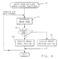
- step 68 If antilock control of brake pressure is not required, the program proceeds to perform background tasks at step 68. These tasks may include diagnostic functions as well as other functions. However, if step 66 determines that a need for antilock brake pressure modulation for any wheel is required, the program proceeds to a step 70 where antilock brake control functions are executed. Once those functions are executed, the program proceeds to the step 68 previously described.
- step 70 when antilock brake control is required establishes the general brake cycle as described wherein when the wheel slip and acceleration conditions represent an incipient wheel lockup condition, a pressure release mode is indicated and brake pressure is released to allow the wheel to recover from the incipient wheel lockup condition and when wheel acceleration and slip conditions represent a recovered condition, an apply mode is indicated and wheel pressure is re-applied and ramped until another incipient wheel lockup condition is sensed at which time the release mode is indicated and the cycle is repeated.
- each channel includes a pressure modulator 18.
- the routine of Figure 4 may be executed four times, once for each wheel with its related parameters.
- the rear brakes may be controlled by a single pressure modulator such that the routine of Figure 4 is then executed once for each front wheel and once for the combined rear wheels.
- step 70 of Figure 3 The antilock brake control functions of step 70 of Figure 3 is entered at step 72 and then proceeds to a step 74 that selects the required brake mode.
- the selection is made from a number of apply modes, such as 3, each having a related rate of increase in brake pressure as a function of wheel acceleration and wheel slip and a number of release modes such as 3 also as a function of wheel acceleration and wheel slip.
- the apply modes provide for higher rates of increase in brake pressure with increasing values of wheel acceleration with decreasing values of wheel slip.
- the release modes provide for control of release of the brake pressure in response to an incipient wheel lockup condition.
- each release mode has associated therewith a calibrated period of rapid pressure release to provide a calibrated pressure reduction. Except for one of the release modes associated with a severe incipient wheel lock condition, each remaining release mode also has associated therewith a calibrated motor brake period.
- the particular brake mode is determined via a lookup table stored in ROM storing the particular brake mode as a function of wheel acceleration and wheel slip.
- the stored brake modes establish a threshold between pressure apply and pressure release as a function of wheel acceleration and wheel slip.
- the lookup table indicates one of the brake release modes whereas if the combination of wheel acceleration and wheel slip represents a recovered condition, the lookup table indicates one of the brake apply modes.
- Step 76 determines whether the brake mode determined at step 72 is one of the apply modes. If not, indicating one of the release modes in response to an incipient lockup condition, the program proceeds to a step 78 which executes a brake release routine in response to the brake release mode established by step 74.
- the brake release routine 78 provides for control of the motor 30 to control brake pressure to allow wheel recovery from the incipient wheel lock condition.
- step 78 stores the commanded motor current as a representation of the motor current at the time the incipient wheel lockup condition is detected. This stored current value represents a measure of the brake pressure producing the maximum brake effort that corresponds to the wheel critical slip. Thereafter, with repeated executions of step 78 for the respective wheel, the brake pressure is released in accordance with the release mode determined at step 74.
- step 74 the lookup table indicates one of the pressure apply modes for the wheel acceleration and wheel slip conditions.
- step 76 determines that step 74 indicates a pressure apply mode
- the program proceeds to a step 80 where a brake apply routine is executed.
- the apply current is first set to a significant fraction of the current stored in step 78 when the incipient lockup condition was first detected.
- step 80 the apply current is ramped at a controlled rate to increase the brake pressure at the wheel brake until an incipient wheel lock condition is again sensed at step 74 when a release mode is determined via the lookup table in response to the wheel acceleration and slip values. Also at step 80, a release duration counter to be used in the brake release routine of step 78 is cleared.
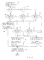
- the routine embodied in the brake release mode of step 78 for controlling the release of the brake pressure is illustrated in Figure 5.
- This routine enters from the brake release routine of step 78 at step 82 and then determines at step 84 whether the pressure release mode determined at step 74 is mode R1 associated with lower values of wheel slip/acceleration. Assuming that mode R1 was determined by step 74, the program proceeds to a step 86 to determine whether or not the duration of release of the brake pressure is greater than a calibration value KT1.
- the value of calibration value KT1 represents the time required for the pressure modulator 18 to reduce the brake pressure in response to a large commanded motor current value KM1 by a calibrated amount determined to effect recovery from the incipient wheel lock condition for the wheel slip and acceleration values associated with release mode R1.
- KT1 may be the period of three control loops effecting a brake pressure reduction of 2,068 kPa (300 psi). Assuming the release period is less than KT1, the program proceeds to a step 88 where the direction command to the motor driver interface circuit 48 is set to a direction to reduce brake pressure and the current command to the motor driver interface circuit 48 is set to KM1. KM1 is a large value providing high motor speed and rapid retraction of the piston 38. Thereafter, the program increments the release duration counter of step 90 after which the program returns to the brake release routine of step 78.
- step 74 determines the release mode as mode R1
- the program repeats the steps 84 through 90 until the release duration KT1 has expired indicating the pressure has been reduced by the amount determined to effect recovery from the incipient wheel lock condition.
- the program executes to a step 92 where the release duration is then compared to a second time period KT2 that is greater than the time period KT1 by an amount equal to the motor brake period associated with release mode R1.
- the motor brake period may be the period of five control loops.
- step 94 the program proceeds to a step 94 where the commanded direction of the motor 30 to the motor driver interface circuit 48 is set to forward direction and the current command is set to a predetermined fraction KFRAC of the current stored at step 78 when step 74 first determined a brake release mode indicating an incipient wheel lockup condition. The resulting current brakes the motor 30 to terminate pressure reduction. The release duration counter is then incremented at step 90. The motor 30 is braked in this manner until the expiration of the period KT2 unless a recovery condition is earlier sensed at step 74.
- step 74 Under normal antilock braking conditions, a recovery condition will be indicated by step 74 during the motor brake period established by KT2. However, if the period KT2 expires before a recovery condition is sensed, the program proceeds from step 92 to a step 96 wherein the motor 30 is commanded in a pressure release direction at a lower rate by commanding a small release current KM2 to the motor driver interface circuit 48. This provides for further release of brake pressure over repeated executions of step 96 to assure wheel recovery from the incipient lockup condition.
- step 98 determines whether or not step 74 has selected mode R2 associated with intermediate values of slip/acceleration. Assuming that mode R2 was selected by step 74, the program proceeds to a step 100 to determine whether or not the duration of release of the brake pressure is greater than a calibration value KT3.
- KT3 represents the time required for the pressure modulator 18 to reduce the brake pressure in response to the large commanded motor current value KM1 by a calibrated amount determined to effect recovery from the incipient wheel lock condition for the wheel slip and acceleration values associated with release mode R2.
- KT3 is greater than KT1 and provides for a larger pressure reduction associated with larger wheel slip/deceleration values.
- KT3 may be the period of six control loops effecting a wheel brake pressure reduction of 3,447 kPa (500 psi). Assuming the release period is less than KT3, the program proceeds to the step 88 where the direction command to the motor driver interface circuit 48 is set to reduce brake pressure and the current command to the motor driver interface circuit 48 is set to KM1. As indicated, this large current command provides high motor speed and rapid retraction of the piston 38. Thereafter, the program increments the release duration counter of step 90 after which the program returns to the brake release routine of step 78.
- step 74 determines the release mode as mode R2
- the program repeats the steps 84, 98, 100, 88 and 90 until the release duration KT3 has expired indicating the pressure has been reduced by the amount determined to effect recovery from the incipient wheel lock condition.
- the program executes to a step 102 where the release duration is then compared to a time period KT4 that is greater than the time period KT3 by an amount equal to the motor brake period associated with release mode R2.
- This brake period is larger than the brake period associated with the release mode R1 due to the higher motor speeds requiring longer brake periods to arrest the motor movement.
- the motor brake period may be the period of twelve control loops.
- step 94 the program proceeds to the step 94 where the commanded direction of the motor 30 to the motor driver interface circuit 48 is set to the pressure apply direction and the current command is set to the predetermined fraction KFRAC of the current stored at step 78 when step 74 first determined a brake release mode indicating an incipient wheel lockup condition. As in the case of release mode R1, the resulting current brakes the motor 30 to terminate pressure reduction. The release duration counter is then incremented at step 90. The motor 30 is braked in this manner until the expiration of the period KT4 unless a recovery condition is earlier sensed at step 74.
- step 74 Under normal antilock braking conditions, a recovery condition will be indicated by step 74 during the motor brake period established by KT4. However, if the period KT4 expires before a recovery condition is sensed, the program proceeds from step 102 to the step 96 wherein the motor 30 is commanded in a pressure release direction at a lower rate by commanding the small release current KM2 to the motor driver interface circuit 48. This provides for further release of brake pressure over repeated executions of step 96 to assure wheel recovery from the incipient lockup condition.
- step 98 if the pressure release mode determined at step 74 is not mode R3 associated with intermediate values of wheel slip/acceleration, the brake mode necessarily then is the remaining release mode R3 associated with more severe incipient wheel lock conditions. With these conditions, it is desirable to continuously release the brake pressure to effect a recovery from the incipient lockup condition. Accordingly, when release mode R3 is indicated, the motor 30 is not braked as in release modes R1 and R3.
- step 98 indicates release mode R3
- the program proceeds to a step 104 to determine whether or not the duration of rapid release of the wheel brake pressure is greater than a calibration value KT5.
- KT5 may be the period of five control loops.
- the program proceeds to the step 88 where the direction command to the motor driver interface circuit 48 is set to reduce brake pressure and the current command to the motor driver interface circuit 48 is set to KM1. As indicated, this large current command provides high motor speed and rapid retraction of the piston 38. Thereafter, the program increments the release duration counter of step 90 after which the program returns to the brake release routine of step 78.
- step 74 determines the release mode as mode R3
- the program repeats the steps 84, 98, 104, 88 and 90 until the release duration KT5 has expired. If the period KT5 expires before a recovery condition is sensed, the program proceeds from step 104 to the step 96 wherein release of brake pressure is continued by commanding the motor 30 in a pressure release direction at the lower rate by commanding the small release current KM2 to the motor driver interface circuit 48. This provides for further release of brake pressure over repeated executions of step 96 to assure wheel recovery from the incipient lockup condition.
- the brake pressure is controlled in response to a sensed incipient wheel lock condition so as to prevent an over release of brake pressure to maximize the braking efficiency of the brake system.
Landscapes
- Engineering & Computer Science (AREA)
- Physics & Mathematics (AREA)
- Fluid Mechanics (AREA)
- Transportation (AREA)
- Mechanical Engineering (AREA)
- Microelectronics & Electronic Packaging (AREA)
- Regulating Braking Force (AREA)
- Control Of Direct Current Motors (AREA)
Claims (8)
- Procédé de commande de la pression de freinage appliquée au frein d'une roue de véhicule roulant sur une surface de route dans un système de freinage possédant un modulateur de pression (18) comprenant un moteur (30) pour générer un couple de moteur en réponse à un courant de moteur pour commander la pression de freinage appliquée, le procédé comprenant les étapes de détection (66, 74, 76) d'un état de commencement de blocage de roue; de détection (74, 76) d'un retour à un état normal de la roue après un état de commencement de blocage; lorsqu'un état de commencement de blocage de roue est détecté, de commande (78) du courant du moteur afin de relâcher la pression de freinage pendant un temps de relâchement s'étendant jusqu'à un état de retour à l'état normal ou la fin d'un temps de relâchement, celui des deux qui se produira en premier le temps de relâchement étant une fonction prédéterminée de paramètres de roue prédéterminés; à l'expiration du temps de relâchement avant un retour détecté à l'état normal après un état de commencement de blocage, de commande (94) du courant de moteur soit pour freiner le moteur soit pour réduire le courant du moteur à une valeur plus faible pour relâcher la pression de freinage jusqu'à ce que la roue retourne à l'état normal après un état de commencement de blocage; et d'augmentation (80) du courant du moteur à la suite d'un retour à la normale de la roue pour augmenter la pression de freinage jusqu'à ce qu'un commencement de blocage de roue soit de nouveau détecté.
- Procédé suivant la revendication 1, dans lequel les paramètres de roue prédéterminés comprennent le glissement de la roue.
- Procédé suivant la revendication 2, dans lequel les paramètres de roue prédéterminés comprennent en outre l'accélération de roue.
- Procédé suivant l'une quelconque des revendications 1 à 3, dans lequel l'étape de commande du courant de moteur pour freiner le moteur comprend la commande du courant à une valeur prédéterminée afin d'appliquer la pression de freinage.
- Procédé suivant la revendication 4, comprenant en outre l'étape de stockage de la valeur du courant du moteur au moment du début de l'état de blocage de la roue est détecté pour la première fois et dans lequel la valeur prédéterminée de courant de moteur possède une relation prédéterminée avec la valeur stockée.
- Procédé suivant l'une quelconque des revendications 1 à 5, dans lequel l'étape de commande de relâchement de la pression de freinage comprend la commande du courant du moteur à une valeur KM1; dans lequel l'étape de commande de freinage du moteur comprend la commande du courant du moteur à une valeur de courant de freinage afin d'appliquer la pression de freinage de manière à freiner le moteur pour achever rapidement le relâchement de la pression de freinage pour une période s'étendant d'un état détecté de retour à la normale après un commencement d'état de blocage de roue ou l'expiration d'un temps de freinage, celui des deux qui se produira le premier; et, à l'expiration du temps de freinage avant un retour à la normale détecté après un commencement d'état de blocage de roue, de commande du courant de moteur à une valeur KM2 afin de relâcher la pression de freinage pendant une période s'étendant jusqu'à un retour à la normale après un commencement d'état de blocage de roue; puis d'augmentation du courant de moteur à la suite d'un retour à la normale détecté pour augmenter la pression de freinage jusqu'à un début de blocage de roue est détecté de nouveau.
- Procédé suivant la revendication 6, dans lequel la valeur KM2 est inférieure à la valeur KM1.
- Procédé suivant la revendication 7, comprenant en outre l'étape de stockage de la valeur de courant de moteur au moment où l'état de commencement de blocage de roue est détecté pour la première fois et dans lequel la valeur de courant de freinage a une relation prédéterminée par rapport à la valeur stockée.
Applications Claiming Priority (2)
| Application Number | Priority Date | Filing Date | Title |
|---|---|---|---|
| US565308 | 1983-12-27 | ||
| US07/565,308 US5106171A (en) | 1990-08-09 | 1990-08-09 | Antilock brake system with step-down release control |
Publications (3)
| Publication Number | Publication Date |
|---|---|
| EP0470657A2 EP0470657A2 (fr) | 1992-02-12 |
| EP0470657A3 EP0470657A3 (en) | 1993-01-13 |
| EP0470657B1 true EP0470657B1 (fr) | 1995-07-05 |
Family
ID=24258043
Family Applications (1)
| Application Number | Title | Priority Date | Filing Date |
|---|---|---|---|
| EP91201873A Expired - Lifetime EP0470657B1 (fr) | 1990-08-09 | 1991-07-16 | Procédé de commande de freinage à antiblocage à commande de relâchement pas à pas |
Country Status (4)
| Country | Link |
|---|---|
| US (1) | US5106171A (fr) |
| EP (1) | EP0470657B1 (fr) |
| JP (1) | JP2709211B2 (fr) |
| DE (1) | DE69110988T2 (fr) |
Families Citing this family (13)
| Publication number | Priority date | Publication date | Assignee | Title |
|---|---|---|---|---|
| CA2080112C (fr) * | 1991-10-08 | 1998-07-28 | Osamu Suzuki | Methode pour estimer la velocite d'un vehicule et methode et systeme de commande de frein |
| US5163743A (en) * | 1991-12-16 | 1992-11-17 | General Motors Corporation | Antilock brake control which induces rear brake lockup upon front brake lockup |
| US5264767A (en) * | 1992-01-21 | 1993-11-23 | General Motors Corporation | Electro-hydraulic control apparatus for improved hydraulic pressure control |
| US5281009A (en) * | 1992-08-19 | 1994-01-25 | General Motors Corporation | Antilock brake system with closed loop control of hold during release |
| JPH07149222A (ja) * | 1993-11-29 | 1995-06-13 | Aisin Seiki Co Ltd | 制動力制御装置 |
| JPH07156770A (ja) * | 1993-12-09 | 1995-06-20 | Aisin Seiki Co Ltd | 制動力制御装置 |
| US5487593A (en) * | 1994-11-23 | 1996-01-30 | Alliedsignal Inc. | Anti-lock braking system providing pump motor duty cycle based on deceleration and motor voltage feed back |
| US5494343A (en) * | 1994-11-23 | 1996-02-27 | Alliedsignal, Inc. | Method of detecting an inoperable pump motor in an anti-lock braking system |
| US7018001B2 (en) * | 2002-02-22 | 2006-03-28 | Delphi Technologies, Inc. | Fast mode release in a force generating apparatus |
| US6655756B2 (en) * | 2002-02-22 | 2003-12-02 | Delphi Technologies, Inc. | Fast mode release in a force generating apparatus using estimated actuator apply chamber pressure |
| US8260514B2 (en) * | 2004-09-24 | 2012-09-04 | Continental Teves Ag & Co. Ohg | Method for supporting a brake system in case of reduced effectiveness |
| WO2009089551A2 (fr) * | 2008-01-11 | 2009-07-16 | General Atomics | Système de freinage à actionneur linéaire |
| JP6900881B2 (ja) * | 2017-11-20 | 2021-07-07 | トヨタ自動車株式会社 | 電動ブレーキ制御装置 |
Family Cites Families (9)
| Publication number | Priority date | Publication date | Assignee | Title |
|---|---|---|---|---|
| DE3201929A1 (de) * | 1982-01-22 | 1983-08-04 | Robert Bosch Gmbh, 7000 Stuttgart | Antiblockiersystem |
| US4576417A (en) * | 1985-02-04 | 1986-03-18 | General Motors Corporation | Power assisted braking system with wheel lock control |
| US4664453A (en) * | 1985-10-21 | 1987-05-12 | General Motors Corporation | Anti-lock brake control system |
| US4781741A (en) | 1986-06-05 | 1988-11-01 | Gte Products Corporation | Process for producing spherical glass particles |
| US4761741A (en) * | 1986-07-07 | 1988-08-02 | General Motors Corporation | Anti-lock brake control system |
| US4750124A (en) * | 1986-11-19 | 1988-06-07 | General Motors Corporation | Anti-lock brake control system |
| US4755946A (en) * | 1986-11-21 | 1988-07-05 | General Motors Corporation | Motor actuated anti-lock brake control system |
| US4756391A (en) * | 1987-07-06 | 1988-07-12 | General Motors Corporation | Brake system actuator with a return spring |
| US4807134A (en) * | 1987-07-09 | 1989-02-21 | General Motors Corporation | DC torque motor actuated anti-lock brake controller |
-
1990
- 1990-08-09 US US07/565,308 patent/US5106171A/en not_active Expired - Fee Related
-
1991
- 1991-07-16 DE DE69110988T patent/DE69110988T2/de not_active Expired - Fee Related
- 1991-07-16 EP EP91201873A patent/EP0470657B1/fr not_active Expired - Lifetime
- 1991-08-09 JP JP3200530A patent/JP2709211B2/ja not_active Expired - Lifetime
Also Published As
| Publication number | Publication date |
|---|---|
| US5106171A (en) | 1992-04-21 |
| EP0470657A3 (en) | 1993-01-13 |
| JP2709211B2 (ja) | 1998-02-04 |
| DE69110988D1 (de) | 1995-08-10 |
| EP0470657A2 (fr) | 1992-02-12 |
| JPH06219261A (ja) | 1994-08-09 |
| DE69110988T2 (de) | 1995-12-07 |
Similar Documents
| Publication | Publication Date | Title |
|---|---|---|
| US5139315A (en) | Vehicle parking brake system and method | |
| US4881784A (en) | ABS pressure apply algorithm | |
| EP0223358B1 (fr) | Appareil de commande de freinage à anti-blocage | |
| EP0470657B1 (fr) | Procédé de commande de freinage à antiblocage à commande de relâchement pas à pas | |
| US5050940A (en) | Brake control and anti-skid system | |
| US5281009A (en) | Antilock brake system with closed loop control of hold during release | |
| US5071199A (en) | Antilock brake system with motor current control | |
| CA2039808C (fr) | Limiteur de lacet sur frein antiblocage | |
| US4835695A (en) | Add-on vehicle wheel slip controller | |
| US4750124A (en) | Anti-lock brake control system | |
| US4969756A (en) | Motor driven actuator speed control | |
| US5454630A (en) | Automotive antilock braking | |
| US4917445A (en) | ABS variant nominal hold pressure | |
| US4673225A (en) | Anti-lock brake control system | |
| US5102207A (en) | Antilock brake system with motor current control of the pressure modulator | |
| US4783127A (en) | Anti-lock brake control system | |
| US5273349A (en) | Antilock brake system with motor current control | |
| CA1290372C (fr) | Systeme antiderapeur commande par moteur electrique | |
| US5315518A (en) | Method and apparatus for initializing antilock brake control on split coefficient surface | |
| EP0459548B1 (fr) | Méthode et appareil pour commander la pression de freinage appliquée à un frein de véhicule | |
| US5669679A (en) | Brake system control | |
| US5385394A (en) | Antilock brake system with controlled pressure augmentation | |
| US5308153A (en) | Antilock brake system with closed loop apply bump | |
| EP0474279B1 (fr) | Procédé et dispositif pour contrôle de pression du freinage |
Legal Events
| Date | Code | Title | Description |
|---|---|---|---|
| PUAI | Public reference made under article 153(3) epc to a published international application that has entered the european phase |
Free format text: ORIGINAL CODE: 0009012 |
|
| AK | Designated contracting states |
Kind code of ref document: A2 Designated state(s): DE FR GB |
|
| PUAL | Search report despatched |
Free format text: ORIGINAL CODE: 0009013 |
|
| AK | Designated contracting states |
Kind code of ref document: A3 Designated state(s): DE FR GB |
|
| 17P | Request for examination filed |
Effective date: 19921224 |
|
| 17Q | First examination report despatched |
Effective date: 19940408 |
|
| GRAA | (expected) grant |
Free format text: ORIGINAL CODE: 0009210 |
|
| AK | Designated contracting states |
Kind code of ref document: B1 Designated state(s): DE FR GB |
|
| REF | Corresponds to: |
Ref document number: 69110988 Country of ref document: DE Date of ref document: 19950810 |
|
| ET | Fr: translation filed | ||
| PLBE | No opposition filed within time limit |
Free format text: ORIGINAL CODE: 0009261 |
|
| STAA | Information on the status of an ep patent application or granted ep patent |
Free format text: STATUS: NO OPPOSITION FILED WITHIN TIME LIMIT |
|
| 26N | No opposition filed | ||
| PGFP | Annual fee paid to national office [announced via postgrant information from national office to epo] |
Ref country code: GB Payment date: 20010618 Year of fee payment: 11 |
|
| PGFP | Annual fee paid to national office [announced via postgrant information from national office to epo] |
Ref country code: FR Payment date: 20010719 Year of fee payment: 11 |
|
| REG | Reference to a national code |
Ref country code: GB Ref legal event code: IF02 |
|
| PG25 | Lapsed in a contracting state [announced via postgrant information from national office to epo] |
Ref country code: GB Free format text: LAPSE BECAUSE OF NON-PAYMENT OF DUE FEES Effective date: 20020716 |
|
| GBPC | Gb: european patent ceased through non-payment of renewal fee |
Effective date: 20020716 |
|
| PG25 | Lapsed in a contracting state [announced via postgrant information from national office to epo] |
Ref country code: FR Free format text: LAPSE BECAUSE OF NON-PAYMENT OF DUE FEES Effective date: 20030331 |
|
| REG | Reference to a national code |
Ref country code: FR Ref legal event code: ST |
|
| PGFP | Annual fee paid to national office [announced via postgrant information from national office to epo] |
Ref country code: DE Payment date: 20050714 Year of fee payment: 15 |
|
| PG25 | Lapsed in a contracting state [announced via postgrant information from national office to epo] |
Ref country code: DE Free format text: LAPSE BECAUSE OF NON-PAYMENT OF DUE FEES Effective date: 20070201 |