EP0470721B1 - V-Motor - Google Patents
V-Motor Download PDFInfo
- Publication number
- EP0470721B1 EP0470721B1 EP19910306632 EP91306632A EP0470721B1 EP 0470721 B1 EP0470721 B1 EP 0470721B1 EP 19910306632 EP19910306632 EP 19910306632 EP 91306632 A EP91306632 A EP 91306632A EP 0470721 B1 EP0470721 B1 EP 0470721B1
- Authority
- EP
- European Patent Office
- Prior art keywords
- engine
- offset
- big end
- bank
- connecting rod
- Prior art date
- Legal status (The legal status is an assumption and is not a legal conclusion. Google has not performed a legal analysis and makes no representation as to the accuracy of the status listed.)
- Expired - Lifetime
Links
- 238000000926 separation method Methods 0.000 claims description 6
- 230000015572 biosynthetic process Effects 0.000 claims description 3
- 238000004519 manufacturing process Methods 0.000 description 7
- 238000010304 firing Methods 0.000 description 3
- 238000003754 machining Methods 0.000 description 3
- 241001125879 Gobio Species 0.000 description 2
- 238000010586 diagram Methods 0.000 description 1
- 238000005516 engineering process Methods 0.000 description 1
Images




Classifications
-
- F—MECHANICAL ENGINEERING; LIGHTING; HEATING; WEAPONS; BLASTING
- F02—COMBUSTION ENGINES; HOT-GAS OR COMBUSTION-PRODUCT ENGINE PLANTS
- F02B—INTERNAL-COMBUSTION PISTON ENGINES; COMBUSTION ENGINES IN GENERAL
- F02B75/00—Other engines
- F02B75/16—Engines characterised by number of cylinders, e.g. single-cylinder engines
- F02B75/18—Multi-cylinder engines
- F02B75/22—Multi-cylinder engines with cylinders in V, fan, or star arrangement
-
- F—MECHANICAL ENGINEERING; LIGHTING; HEATING; WEAPONS; BLASTING
- F02—COMBUSTION ENGINES; HOT-GAS OR COMBUSTION-PRODUCT ENGINE PLANTS
- F02F—CYLINDERS, PISTONS OR CASINGS, FOR COMBUSTION ENGINES; ARRANGEMENTS OF SEALINGS IN COMBUSTION ENGINES
- F02F7/00—Casings, e.g. crankcases
- F02F7/0002—Cylinder arrangements
- F02F7/0012—Crankcases of V-engines
-
- F—MECHANICAL ENGINEERING; LIGHTING; HEATING; WEAPONS; BLASTING
- F16—ENGINEERING ELEMENTS AND UNITS; GENERAL MEASURES FOR PRODUCING AND MAINTAINING EFFECTIVE FUNCTIONING OF MACHINES OR INSTALLATIONS; THERMAL INSULATION IN GENERAL
- F16C—SHAFTS; FLEXIBLE SHAFTS; ELEMENTS OR CRANKSHAFT MECHANISMS; ROTARY BODIES OTHER THAN GEARING ELEMENTS; BEARINGS
- F16C9/00—Bearings for crankshafts or connecting-rods; Attachment of connecting-rods
- F16C9/04—Connecting-rod bearings; Attachments thereof
-
- F—MECHANICAL ENGINEERING; LIGHTING; HEATING; WEAPONS; BLASTING
- F02—COMBUSTION ENGINES; HOT-GAS OR COMBUSTION-PRODUCT ENGINE PLANTS
- F02B—INTERNAL-COMBUSTION PISTON ENGINES; COMBUSTION ENGINES IN GENERAL
- F02B75/00—Other engines
- F02B75/16—Engines characterised by number of cylinders, e.g. single-cylinder engines
- F02B75/18—Multi-cylinder engines
- F02B2075/1804—Number of cylinders
- F02B2075/1824—Number of cylinders six
-
- F—MECHANICAL ENGINEERING; LIGHTING; HEATING; WEAPONS; BLASTING
- F02—COMBUSTION ENGINES; HOT-GAS OR COMBUSTION-PRODUCT ENGINE PLANTS
- F02B—INTERNAL-COMBUSTION PISTON ENGINES; COMBUSTION ENGINES IN GENERAL
- F02B75/00—Other engines
- F02B75/16—Engines characterised by number of cylinders, e.g. single-cylinder engines
- F02B75/18—Multi-cylinder engines
- F02B2075/1804—Number of cylinders
- F02B2075/1832—Number of cylinders eight
-
- F—MECHANICAL ENGINEERING; LIGHTING; HEATING; WEAPONS; BLASTING
- F02—COMBUSTION ENGINES; HOT-GAS OR COMBUSTION-PRODUCT ENGINE PLANTS
- F02B—INTERNAL-COMBUSTION PISTON ENGINES; COMBUSTION ENGINES IN GENERAL
- F02B69/00—Internal-combustion engines convertible into other combustion-engine type, not provided for in F02B11/00; Internal-combustion engines of different types characterised by constructions facilitating use of same main engine-parts in different types
Definitions
- the invention relates to piston engines and to their manufacture. Particularly it relates to V-type engines in a series which includes a V6 type and a V8 type which are well known as motor vehicle power units.
- the V8 type of engine commonly has two banks of four cylinders with the banks at 90 degrees to each other. It uses a crankshaft having four crank throws and four crankpins so that the big end bearing of the connecting rod of each cylinder in one bank and the big end bearing of the connecting rod of the opposite cylinder in the other bank are journalled side by side on a common crankpin.
- the crankpin is of uniform diameter and axis and there is no substantial separation between adjacent side faces of the big end bearings.
- the cylinders of one bank are offset relative to the crankpin axis from those of the other bank by an amount equivalent to the axial distance between the side faces of one big end bearing, this being called the bank offset.
- the V6 type of engine commonly uses a crankshaft having three crank throws and three crankpins.
- the big end bearing of the connecting rod of each cylinder in one bank and the big end bearing of the connecting rod of the opposite cylinder in the other bank are journalled side by side on a common crankpin.
- the crankpin is of uniform diameter and axis and there is no substantial separation between adjacent side faces of the big end bearings then the cylinder banks have to be arranged at 60 degrees to each other if engine firing intervals are to be even.
- a series of piston engines each engine in the series having an engine block comprising two banks of two or more cylinders arranged in V formation, a crankshaft journalled in the engine block and having two or more crankpins, pistons, each guided for reciprocal movement in a respective cylinder bore, and connecting rods, each having a small end bearing at one end connected to a respective piston and a big end bearing at the other end, each engine of the series having the big end bearing of the connecting rod of each cylinder in one bank and the big end bearing of the connecting rod of the opposite cylinder in the other bank journalled side by side on a respective one of the crankpins, the series including one type of engine which has each of the respective crankpins formed with a uniform diameter and axis and which has no substantial separation between adjacent side faces of the respective big end bearings and including another type of engine having a different number of cylinders to the first type of engine and which has each of the respective crankpins formed with offset axes and which has axial separation of adjacent
- said one type of engine has the axis of each cylinder, relative to the crankshaft axis, offset from the axial centre of the respective big end bearing by an amount also called the connecting rod offset and is arranged so that the bank offset is greater than the distance between axial centres of the big end bearings on each of the respective crankpins.
- the connecting rods offsets of both said one and said other types of engine in the series may be identical, as may the cylinder bores or the connecting rods themselves.
- an engine of said other type may be characterised in that the magnitude of the connecting rod offset is one quarter of the axial distance separating adjacent side faces of the big end bearings on each of the crankpins.
- Figs 1 to 6 illustrate known V8 and V6 piston engine technology.
- Fig 1 shows an engine block 11 having one bank 12 of cylinders and another bank 13 of cylinders arranged in V formation with the banks at 90 degrees to each other.
- Fig 2 shows the axes of the cylinders in one bank labelled 1 to 4 and the axes of the cylinders the other bank labelled 5 to 8.
- the journal bearings are shown diagrammatically in Fig 2 at 15.
- Pistons 16 are reciprocal in cylinder bores and are connected to the crankshaft by connecting rods 17, each having a small end bearing 18 at one end connected to the piston through a gudgeon pin 19 and a big end bearing 21 at the other end connected to a crankpin 22 which forms part of the crankshaft 14.
- the big end bearing 21 of the connecting rod 17 of each cylinder in the one bank 12 and the big end bearing of the connecting rod of each cylinder in the other bank 13 are journalled side by side on a respective crankpin 22 so that the crankpin is common to both.
- crankpin 22 is formed with a uniform diameter and axis 23 and there is no substantial clearance between adjacent side faces 24 of the big end bearings 21.
- Each connecting rod 17 and its bearings 18 and 21 are arranged symmetrically central relative to the respective cylinder axis 25 and 26 (Fig 4).
- the cylinders, as illustrated by axes 25 and 26, are axially offset relative to the axis of crankshaft 14 by an amount L1 which, by virtue of the symmetry of the connecting rods, is equivalent to the axial distance between opposite side faces of one of the big end bearings 21.
- the offset L1 is termed the bank offset to denote the amount by which one bank of cylinders is offset from the other.
- crankpin 22a has offset axes 23a and 23b.
- the cylindrical portions of the crankpin 22a defined by axes 23a and 23b are separated by an integral collar or web 27.
- Annular steps 28 on each side of the collar 27 provide axial location bearing faces for the connecting rods.
- crankpin axes 23a and 23b are offset by an amount which is equivalent to an angle A (Fig 6) between the crank throws, that is the lines between the crankshaft axis 29 and the crankpin axes 23a and 23b.
- This crankpin offset is required to give even firing intervals when the V6 engine retains the same 90 degrees between the bank angles as is used on the V8 engine.
- the presence of the collar 27, including the steps 28, means that the connecting rods 17 are spaced apart a distance L2 which is equivalent to L1 plus the axial width of the collar.
- L2 is also the bank offset
- V6 engine cannot be made on the same production facilities as the V8 engine if mass-production methods are to be exploited to the full. For example, it would be normal practice to machine all eight or all six cylinder bores simultaneously using multiple boring heads at fixed centres.
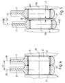
- Figs 7 and 8 show how the known V6 and V 8 engines are modified in a preferred embodiment of the invention. Where appropriate the same reference numerals as those used in Figs 1 to 6 are used.
- the common bank offset is obtained by having the axis 29 of each cylinder offset by a distance L4 relative to the crankshaft axis from the axial centre 31 of the respective big end bearing 21.
- This offset L4 is referred to as the connecting rod offset and is achieved here by having the small end bearing 18 of each connecting rod 17a arranged centrally about the axis 29 of the respective cylinder so that its axial centre coincides with the cylinder axis 29 and is offset relative to the axial centre 31 of the big end bearing, this being known as an offset connecting rod.
- the same connecting rod offset L4 is one quarter of the axial distance between opposite side faces of the big end bearings on a common crankpin of the V6 type engine, then the same connecting rod offset can be used for both the V6 and V8 type engines.
- This axial distance is the same as the axial width L3 of the collar 27 (Fig 8). It thus follows that the same connecting rods can be used for a family of engines which includes both the V6 and V8 types.
- the connecting rod offsets L4 are arranged so that the bank offset L5 is greater than the distance L6 between the axial centres 31 of the big end bearings 21 on each of the crankpins 22 and in the V6 engine (Fig 8) the connecting rod offsets L4 are arranged so that the bank offset L5 is less than the distance L7 between axial centres 31 of the respective big end bearings.
- V8 engine has no connecting rod offset whilst the V6 engine has its connecting rod offset doubled compared to that just described above.
- An alternative to the offset connecting rod is a piston with gudgeon pin bosses arranged to give clearance to a small end bearing which is offset relative to the cylinder axis but central relative to the big end bearing. This may be achieved either by having one longer and one shorter boss or by having small and large side clearances between the small end bearing and the bosses.
- the invention may be applied to series or families of V type engines with other numbers of cylinders where connecting rods of pairs of cylinders of each bank are journalled side by side on a common crank pin and a common bank offset is to be achieved. It may also be applied to series of engines in which the banks of cylinders are arranged at an angle other than 90 degrees to each other.
Landscapes
- Engineering & Computer Science (AREA)
- General Engineering & Computer Science (AREA)
- Mechanical Engineering (AREA)
- Chemical & Material Sciences (AREA)
- Combustion & Propulsion (AREA)
- Shafts, Cranks, Connecting Bars, And Related Bearings (AREA)
- Cylinder Crankcases Of Internal Combustion Engines (AREA)
- Pistons, Piston Rings, And Cylinders (AREA)
- Hydraulic Motors (AREA)
Claims (8)
- Baureihe von Hubkolbenmotoren, wobei jeder Motor der Baureihe einen Motorblock (11) mit zwei Reihen (12,13) von zwei oder mehr V-förmig angeordneten Zylindern, eine Kurbelwelle (14), die im Motorblock gelagert ist und zwei oder mehr Kurbelzapfen (22, 22a) aufweist, Kolben (16), jeweils zur wechselseitigen Bewegung in einer jeweiligen Zylinderbohrung geführt, und Pleuel (17a) umfaßt, die jeweils an einem Ende ein Pleuelaugenlager (18), das mit einem entsprechenden Kolben verbunden ist, und am anderen Ende ein Pleuelhauptlager (21) aufweisen, wobei bei jedem Motor der Baureihe das Pleuelhauptlager des Pleuels jedes Zylinders in einer Reihe (12) und das Pleuelhauptlager des Pleuels des gegenüberliegenden Zylinders in der anderen Reihe (13) nebeneinander auf einem jeweiligen Kurbelzapfen gelagert sind, wobei die Baureihe eine Motorart umfaßt, bei der jeder der entsprechenden Kurbelzapfen (22) mit einem gleichmäßigen Durchmesser und mit einer gleichmäßigen Achse (23) ausgebildet ist und bei der es keinen wesentlichen Abstand zwischen benachbarten Seitenflächen (24) der jeweiligen Pleuelhauptlager (21) gibt, sowie eine andere Motorart, die eine von der ersten Motorart verschiedene Anzahl von Zylindern aufweist und bei der jeder der entsprechenden Kurbelzapfen (22a) mit versetzten Achsen (23a, 23b) ausgebildet ist und benachbarte Seitenflächen der jeweiligen Pleuelhauptlager axial beabstandet sind, wobei die Achsen (29) der Zylinder einer Reihe (12) sowohl bei jener einen als auch bei jener anderen Motorart im Verhältnis zur Kurbelwellenachse zu den Achsen der Zylinder der anderen Reihe (13) um ein als Reihenversatz (L5) bezeichnetes Maß versetzt sind, das den beiden Motorarten gemein ist, wobei die Achse (29) jedes Zylinders bei jener anderen Motorart im Verhältnis zur Kurbelwellenachse zum axialen Mittelpunkt (31) des jeweiligen Pleuelhauptlagers (21) um ein Maß versetzt ist, das als Pleuelversatz (L4) bezeichnet wird, und jene andere Motorart so angeordnet ist, daß der Reihenversatz (L5) geringer ist als der Abstand (L7) zwischen den axialen Mittelpunkten der Pleuelhauptlager an jedem der jeweiligen Kurbelzapfen (22a).
- Baureihe nach Anspruch 1, dadurch gekennzeichnet, daß die Achse (29) jedes Zylinders bei jener einen Motorart im Verhältnis zur Kurbelwellenachse zum axialen Mittelpunkt (31) des jeweiligen Pleuelhauptlagers (21) um ein Maß versetzt ist, das auch als Pleuelversatz (L4) bezeichnet wird, und jene eine Motorart so angeordnet ist, daß der Reihenversatz (L5) größer ist als der Abstand (L6) zwischen den axialen Mittelpunkten der Pleuelhauptlager an jedem der jeweiligen Kurbelzapfen (22).
- Baureihe nach Anspruch 2, dadurch gekennzeichnet, daß das Pleuelaugenlager (18) jedes Pleuels (17a) mittig um die Achse (29) des jeweiligen Zylinders angeordnet ist, so daß sein axialer Mittelpunkt im Verhältnis zum axialen Mittelpunkt (31) des jeweiligen Pleuelhauptlagers (21) versetzt ist.
- Baureihe nach Anspruch 2 oder 3, dadurch gekennzeichnet, daß der Pleuelversatz (L4) von sowohl jener einen als auch jener anderen Motorart identisch sind.
- Baureihe nach Anspruch 4, dadurch gekennzeichnet, daß die Zylinderbohrungen von sowohl jener einen als auch jener anderen Motorart identisch sind.
- Baureihe nach Anspruch 4 oder 5, dadurch gekennzeichnet, daß die Pleuel (17a) von sowohl jener einen als auch jener anderen Motorart identisch sind.
- Baureihe nach einem der vorhergehenden Ansprüche, dadurch gekennzeichnet, daß es sich bei jener einen Motorart um einen V8 und jener anderen Motorart um einen V6 handelt.
- Baureihe nach einem der Ansprüche 4 bis 7, wobei ein Motor jener anderen Art dadurch gekennzeichnet ist, daß die Größe des Pleuelversatzes (L4) ein Viertel des axialen Abstands (L3) zwischen benachbarten Seitenflächen (24) der Pleuelhauptlager (21) auf jedem der Kurbelzapfen (22a) beträgt.
Priority Applications (1)
| Application Number | Priority Date | Filing Date | Title |
|---|---|---|---|
| EP94201979A EP0628708B1 (de) | 1990-08-07 | 1991-07-22 | Kolbenmaschine mit V-förmig aufgestellten Zylindern |
Applications Claiming Priority (2)
| Application Number | Priority Date | Filing Date | Title |
|---|---|---|---|
| GB9017261 | 1990-08-07 | ||
| GB909017261A GB9017261D0 (en) | 1990-08-07 | 1990-08-07 | Piston engines and manufacture thereof |
Related Child Applications (1)
| Application Number | Title | Priority Date | Filing Date |
|---|---|---|---|
| EP94201979.5 Division-Into | 1991-07-22 |
Publications (2)
| Publication Number | Publication Date |
|---|---|
| EP0470721A1 EP0470721A1 (de) | 1992-02-12 |
| EP0470721B1 true EP0470721B1 (de) | 1995-04-05 |
Family
ID=10680263
Family Applications (2)
| Application Number | Title | Priority Date | Filing Date |
|---|---|---|---|
| EP94201979A Expired - Lifetime EP0628708B1 (de) | 1990-08-07 | 1991-07-22 | Kolbenmaschine mit V-förmig aufgestellten Zylindern |
| EP19910306632 Expired - Lifetime EP0470721B1 (de) | 1990-08-07 | 1991-07-22 | V-Motor |
Family Applications Before (1)
| Application Number | Title | Priority Date | Filing Date |
|---|---|---|---|
| EP94201979A Expired - Lifetime EP0628708B1 (de) | 1990-08-07 | 1991-07-22 | Kolbenmaschine mit V-förmig aufgestellten Zylindern |
Country Status (4)
| Country | Link |
|---|---|
| EP (2) | EP0628708B1 (de) |
| DE (2) | DE69108635T2 (de) |
| ES (2) | ES2072549T3 (de) |
| GB (2) | GB9017261D0 (de) |
Cited By (2)
| Publication number | Priority date | Publication date | Assignee | Title |
|---|---|---|---|---|
| GB2246814B (en) * | 1990-08-07 | 1994-02-16 | Rover Group | Piston engines and manufacture thereof |
| DE102006048108A1 (de) * | 2006-10-11 | 2008-04-30 | Audi Ag | V-Motor |
Families Citing this family (5)
| Publication number | Priority date | Publication date | Assignee | Title |
|---|---|---|---|---|
| SE9700622D0 (sv) | 1997-02-21 | 1997-02-21 | Ericsson Telefon Ab L M | Anordning och metod vid datanät |
| DE10350520B4 (de) * | 2003-10-29 | 2008-01-17 | Audi Ag | Brennkraftmaschine mit mindestens zwei Zylinderbänken |
| DE102004021360B4 (de) * | 2004-04-30 | 2009-03-19 | Audi Ag | Brennkraftmaschine mit Zylinderpaaren |
| DE102006017923B4 (de) * | 2006-04-18 | 2017-09-28 | Audi Ag | Verfahren zur Pleuelmontage, Pleuel sowie Kurbelwelle mit Pleuel |
| DE102008031993B4 (de) * | 2008-07-07 | 2018-01-11 | Audi Ag | Split-Pin-Kurbelwelle und Verfahren zur Auslegung einer Familie von V-Motoren |
Family Cites Families (7)
| Publication number | Priority date | Publication date | Assignee | Title |
|---|---|---|---|---|
| US2344275A (en) * | 1941-04-08 | 1944-03-14 | Int Harvester Co | Bearing |
| DE1027009B (de) * | 1956-10-01 | 1958-03-27 | Carl Kaelble | Brennkraftmaschine mit V-foermig angeordneten Zylindern |
| CH376712A (de) * | 1960-01-13 | 1964-04-15 | Schweizerische Lokomotiv | Verbrennungskraftmaschinensatz mit unter einem Gabelwinkel zueinander stehenden Zylinderreihen |
| US3116724A (en) * | 1960-01-13 | 1964-01-07 | Schweizerische Lokomotiv | Internal combustion engines |
| JPS6141034A (ja) * | 1984-08-02 | 1986-02-27 | Toyota Motor Corp | V型8気筒四サイクル内燃機関 |
| GB9017261D0 (en) * | 1990-08-07 | 1990-09-19 | Rover Group | Piston engines and manufacture thereof |
| DE4025927A1 (de) * | 1990-08-16 | 1992-02-20 | Daimler Benz Ag | Baureihe von hubkolben-brennkraftmaschinen in v-bauweise |
-
1990
- 1990-08-07 GB GB909017261A patent/GB9017261D0/en active Pending
-
1991
- 1991-07-19 GB GB9115616A patent/GB2246814B/en not_active Expired - Lifetime
- 1991-07-22 ES ES91306632T patent/ES2072549T3/es not_active Expired - Lifetime
- 1991-07-22 DE DE1991608635 patent/DE69108635T2/de not_active Expired - Lifetime
- 1991-07-22 ES ES94201979T patent/ES2096406T3/es not_active Expired - Lifetime
- 1991-07-22 EP EP94201979A patent/EP0628708B1/de not_active Expired - Lifetime
- 1991-07-22 DE DE1991623463 patent/DE69123463T2/de not_active Expired - Lifetime
- 1991-07-22 EP EP19910306632 patent/EP0470721B1/de not_active Expired - Lifetime
Cited By (2)
| Publication number | Priority date | Publication date | Assignee | Title |
|---|---|---|---|---|
| GB2246814B (en) * | 1990-08-07 | 1994-02-16 | Rover Group | Piston engines and manufacture thereof |
| DE102006048108A1 (de) * | 2006-10-11 | 2008-04-30 | Audi Ag | V-Motor |
Also Published As
| Publication number | Publication date |
|---|---|
| DE69123463D1 (de) | 1997-01-16 |
| GB2246814B (en) | 1994-02-16 |
| EP0628708A1 (de) | 1994-12-14 |
| DE69108635T2 (de) | 1995-12-07 |
| DE69108635D1 (de) | 1995-05-11 |
| EP0628708B1 (de) | 1996-12-04 |
| GB2246814A (en) | 1992-02-12 |
| ES2096406T3 (es) | 1997-03-01 |
| GB9115616D0 (en) | 1991-09-04 |
| EP0470721A1 (de) | 1992-02-12 |
| ES2072549T3 (es) | 1995-07-16 |
| DE69123463T2 (de) | 1997-05-28 |
| GB9017261D0 (en) | 1990-09-19 |
Similar Documents
| Publication | Publication Date | Title |
|---|---|---|
| CA1206828A (en) | Crankshaft fixing device for v-type engine | |
| US4622864A (en) | Modular crank subassembly and built-up crankshaft therefor | |
| US6857411B2 (en) | Lubricating oil supply system for the connecting rod bearings of a crankshaft of a multi-cylinder internal-combustion engine | |
| EP0470721B1 (de) | V-Motor | |
| US3978828A (en) | V-Type internal combustion engine | |
| EA000287B1 (ru) | Двигатель внутреннего сгорания с поршнями возвратно-поступательного хода с кривошипом и множеством круговых блоков скольжения | |
| US4787342A (en) | V-6 engine | |
| CZ283066B6 (cs) | Dvoudobý spalovací motor | |
| US4002087A (en) | Machine crank-shaft with improved dynamic balance ratio | |
| CA2186175A1 (en) | Main bearing structure for internal combustion engine | |
| CA1157381A (en) | Six cylinder two stroke engine with torsional resonance control | |
| ATE179496T1 (de) | Herstellungsverfahren einer kurbelwelle für eine brennkraftmaschine mit mehreren zylindern | |
| US4519344A (en) | V-type internal combustion engine | |
| US2899015A (en) | Engine bearings and lubrication system | |
| US11313409B1 (en) | Crankshaft and cranktrain for internal combustion engine | |
| US2680427A (en) | V-type engine | |
| US3279267A (en) | Reciprocating machine and a method for assembling it | |
| DE19716274A1 (de) | Hubkolben-Brennkraftmaschine | |
| EP0441834B1 (de) | Pleuellagerung für Sternmotor | |
| US3241896A (en) | Bearing for a reciprocating machine and method for assembling it | |
| US3116724A (en) | Internal combustion engines | |
| US5927243A (en) | Internal combustion engine with siamesed cylinder bores and pistons | |
| US2237685A (en) | Assembled crankshaft | |
| US2371797A (en) | Engine crankcase construction | |
| KR200476164Y1 (ko) | 복수의 실린더가 행으로 배치되어 있는 내연 기관 |
Legal Events
| Date | Code | Title | Description |
|---|---|---|---|
| PUAI | Public reference made under article 153(3) epc to a published international application that has entered the european phase |
Free format text: ORIGINAL CODE: 0009012 |
|
| AK | Designated contracting states |
Kind code of ref document: A1 Designated state(s): DE ES FR GB IT |
|
| 17P | Request for examination filed |
Effective date: 19920713 |
|
| 17Q | First examination report despatched |
Effective date: 19930521 |
|
| RAP1 | Party data changed (applicant data changed or rights of an application transferred) |
Owner name: ROVER GROUP LIMITED |
|
| GRAA | (expected) grant |
Free format text: ORIGINAL CODE: 0009210 |
|
| AK | Designated contracting states |
Kind code of ref document: B1 Designated state(s): DE ES FR IT |
|
| XX | Miscellaneous (additional remarks) |
Free format text: TEILANMELDUNG 94201979.5 EINGEREICHT AM 22/07/91. |
|
| REF | Corresponds to: |
Ref document number: 69108635 Country of ref document: DE Date of ref document: 19950511 |
|
| RAP2 | Party data changed (patent owner data changed or rights of a patent transferred) |
Owner name: ROVER GROUP LIMITED Owner name: KIA MOTORS CORPORATION |
|
| ET | Fr: translation filed | ||
| ITF | It: translation for a ep patent filed | ||
| RAP2 | Party data changed (patent owner data changed or rights of a patent transferred) |
Owner name: ROVER GROUP LIMITED Owner name: KIA MOTORS CORPORATION |
|
| REG | Reference to a national code |
Ref country code: ES Ref legal event code: FG2A Ref document number: 2072549 Country of ref document: ES Kind code of ref document: T3 |
|
| PLBE | No opposition filed within time limit |
Free format text: ORIGINAL CODE: 0009261 |
|
| STAA | Information on the status of an ep patent application or granted ep patent |
Free format text: STATUS: NO OPPOSITION FILED WITHIN TIME LIMIT |
|
| 26N | No opposition filed | ||
| REG | Reference to a national code |
Ref country code: FR Ref legal event code: CA |
|
| PGFP | Annual fee paid to national office [announced via postgrant information from national office to epo] |
Ref country code: ES Payment date: 20100618 Year of fee payment: 20 |
|
| PGFP | Annual fee paid to national office [announced via postgrant information from national office to epo] |
Ref country code: DE Payment date: 20100903 Year of fee payment: 20 Ref country code: FR Payment date: 20100809 Year of fee payment: 20 Ref country code: IT Payment date: 20100717 Year of fee payment: 20 |
|
| REG | Reference to a national code |
Ref country code: DE Ref legal event code: R071 Ref document number: 69108635 Country of ref document: DE |
|
| REG | Reference to a national code |
Ref country code: DE Ref legal event code: R071 Ref document number: 69108635 Country of ref document: DE |
|
| REG | Reference to a national code |
Ref country code: ES Ref legal event code: FD2A Effective date: 20120206 |
|
| PG25 | Lapsed in a contracting state [announced via postgrant information from national office to epo] |
Ref country code: ES Free format text: LAPSE BECAUSE OF EXPIRATION OF PROTECTION Effective date: 20110723 |
|
| PG25 | Lapsed in a contracting state [announced via postgrant information from national office to epo] |
Ref country code: DE Free format text: LAPSE BECAUSE OF EXPIRATION OF PROTECTION Effective date: 20110723 |