EP0470874A1 - Brennkraftmaschine mit Lufteinlasseinrichtung integriert in einem Zylinderkopf - Google Patents
Brennkraftmaschine mit Lufteinlasseinrichtung integriert in einem Zylinderkopf Download PDFInfo
- Publication number
- EP0470874A1 EP0470874A1 EP91401889A EP91401889A EP0470874A1 EP 0470874 A1 EP0470874 A1 EP 0470874A1 EP 91401889 A EP91401889 A EP 91401889A EP 91401889 A EP91401889 A EP 91401889A EP 0470874 A1 EP0470874 A1 EP 0470874A1
- Authority
- EP
- European Patent Office
- Prior art keywords
- cylinder head
- intake
- head cover
- partitions
- internal combustion
- Prior art date
- Legal status (The legal status is an assumption and is not a legal conclusion. Google has not performed a legal analysis and makes no representation as to the accuracy of the status listed.)
- Granted
Links
- 238000002485 combustion reaction Methods 0.000 title claims abstract description 8
- 238000005192 partition Methods 0.000 claims abstract description 13
- 230000000295 complement effect Effects 0.000 claims description 3
- 210000004027 cell Anatomy 0.000 description 5
- 238000010586 diagram Methods 0.000 description 1
- 239000000446 fuel Substances 0.000 description 1
- 238000002347 injection Methods 0.000 description 1
- 239000007924 injection Substances 0.000 description 1
- 238000000034 method Methods 0.000 description 1
- 230000004048 modification Effects 0.000 description 1
- 238000012986 modification Methods 0.000 description 1
- 230000035515 penetration Effects 0.000 description 1
Images




Classifications
-
- F—MECHANICAL ENGINEERING; LIGHTING; HEATING; WEAPONS; BLASTING
- F02—COMBUSTION ENGINES; HOT-GAS OR COMBUSTION-PRODUCT ENGINE PLANTS
- F02F—CYLINDERS, PISTONS OR CASINGS, FOR COMBUSTION ENGINES; ARRANGEMENTS OF SEALINGS IN COMBUSTION ENGINES
- F02F1/00—Cylinders; Cylinder heads
- F02F1/24—Cylinder heads
- F02F1/42—Shape or arrangement of intake or exhaust channels in cylinder heads
- F02F1/4235—Shape or arrangement of intake or exhaust channels in cylinder heads of intake channels
-
- F—MECHANICAL ENGINEERING; LIGHTING; HEATING; WEAPONS; BLASTING
- F02—COMBUSTION ENGINES; HOT-GAS OR COMBUSTION-PRODUCT ENGINE PLANTS
- F02F—CYLINDERS, PISTONS OR CASINGS, FOR COMBUSTION ENGINES; ARRANGEMENTS OF SEALINGS IN COMBUSTION ENGINES
- F02F1/00—Cylinders; Cylinder heads
- F02F1/24—Cylinder heads
- F02F1/243—Cylinder heads and inlet or exhaust manifolds integrally cast together
-
- F—MECHANICAL ENGINEERING; LIGHTING; HEATING; WEAPONS; BLASTING
- F02—COMBUSTION ENGINES; HOT-GAS OR COMBUSTION-PRODUCT ENGINE PLANTS
- F02F—CYLINDERS, PISTONS OR CASINGS, FOR COMBUSTION ENGINES; ARRANGEMENTS OF SEALINGS IN COMBUSTION ENGINES
- F02F1/00—Cylinders; Cylinder heads
- F02F1/24—Cylinder heads
- F02F1/42—Shape or arrangement of intake or exhaust channels in cylinder heads
- F02F1/4214—Shape or arrangement of intake or exhaust channels in cylinder heads specially adapted for four or more valves per cylinder
- F02F1/4221—Shape or arrangement of intake or exhaust channels in cylinder heads specially adapted for four or more valves per cylinder particularly for three or more inlet valves
-
- F—MECHANICAL ENGINEERING; LIGHTING; HEATING; WEAPONS; BLASTING
- F02—COMBUSTION ENGINES; HOT-GAS OR COMBUSTION-PRODUCT ENGINE PLANTS
- F02F—CYLINDERS, PISTONS OR CASINGS, FOR COMBUSTION ENGINES; ARRANGEMENTS OF SEALINGS IN COMBUSTION ENGINES
- F02F7/00—Casings, e.g. crankcases
- F02F7/006—Camshaft or pushrod housings
-
- F—MECHANICAL ENGINEERING; LIGHTING; HEATING; WEAPONS; BLASTING
- F02—COMBUSTION ENGINES; HOT-GAS OR COMBUSTION-PRODUCT ENGINE PLANTS
- F02M—SUPPLYING COMBUSTION ENGINES IN GENERAL WITH COMBUSTIBLE MIXTURES OR CONSTITUENTS THEREOF
- F02M35/00—Combustion-air cleaners, air intakes, intake silencers, or induction systems specially adapted for, or arranged on, internal-combustion engines
- F02M35/10—Air intakes; Induction systems
- F02M35/10006—Air intakes; Induction systems characterised by the position of elements of the air intake system in direction of the air intake flow, i.e. between ambient air inlet and supply to the combustion chamber
- F02M35/10026—Plenum chambers
- F02M35/10052—Plenum chambers special shapes or arrangements of plenum chambers; Constructional details
-
- F—MECHANICAL ENGINEERING; LIGHTING; HEATING; WEAPONS; BLASTING
- F02—COMBUSTION ENGINES; HOT-GAS OR COMBUSTION-PRODUCT ENGINE PLANTS
- F02M—SUPPLYING COMBUSTION ENGINES IN GENERAL WITH COMBUSTIBLE MIXTURES OR CONSTITUENTS THEREOF
- F02M35/00—Combustion-air cleaners, air intakes, intake silencers, or induction systems specially adapted for, or arranged on, internal-combustion engines
- F02M35/10—Air intakes; Induction systems
- F02M35/10006—Air intakes; Induction systems characterised by the position of elements of the air intake system in direction of the air intake flow, i.e. between ambient air inlet and supply to the combustion chamber
- F02M35/10072—Intake runners
-
- F—MECHANICAL ENGINEERING; LIGHTING; HEATING; WEAPONS; BLASTING
- F02—COMBUSTION ENGINES; HOT-GAS OR COMBUSTION-PRODUCT ENGINE PLANTS
- F02M—SUPPLYING COMBUSTION ENGINES IN GENERAL WITH COMBUSTIBLE MIXTURES OR CONSTITUENTS THEREOF
- F02M35/00—Combustion-air cleaners, air intakes, intake silencers, or induction systems specially adapted for, or arranged on, internal-combustion engines
- F02M35/10—Air intakes; Induction systems
- F02M35/10091—Air intakes; Induction systems characterised by details of intake ducts: shapes; connections; arrangements
- F02M35/10104—Substantially vertically arranged ducts
-
- F—MECHANICAL ENGINEERING; LIGHTING; HEATING; WEAPONS; BLASTING
- F02—COMBUSTION ENGINES; HOT-GAS OR COMBUSTION-PRODUCT ENGINE PLANTS
- F02M—SUPPLYING COMBUSTION ENGINES IN GENERAL WITH COMBUSTIBLE MIXTURES OR CONSTITUENTS THEREOF
- F02M35/00—Combustion-air cleaners, air intakes, intake silencers, or induction systems specially adapted for, or arranged on, internal-combustion engines
- F02M35/10—Air intakes; Induction systems
- F02M35/10242—Devices or means connected to or integrated into air intakes; Air intakes combined with other engine or vehicle parts
- F02M35/10288—Air intakes combined with another engine part, e.g. cylinder head cover or being cast in one piece with the exhaust manifold, cylinder head or engine block
-
- F—MECHANICAL ENGINEERING; LIGHTING; HEATING; WEAPONS; BLASTING
- F02—COMBUSTION ENGINES; HOT-GAS OR COMBUSTION-PRODUCT ENGINE PLANTS
- F02M—SUPPLYING COMBUSTION ENGINES IN GENERAL WITH COMBUSTIBLE MIXTURES OR CONSTITUENTS THEREOF
- F02M35/00—Combustion-air cleaners, air intakes, intake silencers, or induction systems specially adapted for, or arranged on, internal-combustion engines
- F02M35/10—Air intakes; Induction systems
- F02M35/104—Intake manifolds
- F02M35/108—Intake manifolds with primary and secondary intake passages
- F02M35/1085—Intake manifolds with primary and secondary intake passages the combustion chamber having multiple intake valves
-
- F—MECHANICAL ENGINEERING; LIGHTING; HEATING; WEAPONS; BLASTING
- F02—COMBUSTION ENGINES; HOT-GAS OR COMBUSTION-PRODUCT ENGINE PLANTS
- F02B—INTERNAL-COMBUSTION PISTON ENGINES; COMBUSTION ENGINES IN GENERAL
- F02B1/00—Engines characterised by fuel-air mixture compression
- F02B1/02—Engines characterised by fuel-air mixture compression with positive ignition
- F02B1/04—Engines characterised by fuel-air mixture compression with positive ignition with fuel-air mixture admission into cylinder
-
- F—MECHANICAL ENGINEERING; LIGHTING; HEATING; WEAPONS; BLASTING
- F02—COMBUSTION ENGINES; HOT-GAS OR COMBUSTION-PRODUCT ENGINE PLANTS
- F02B—INTERNAL-COMBUSTION PISTON ENGINES; COMBUSTION ENGINES IN GENERAL
- F02B2275/00—Other engines, components or details, not provided for in other groups of this subclass
- F02B2275/18—DOHC [Double overhead camshaft]
-
- F—MECHANICAL ENGINEERING; LIGHTING; HEATING; WEAPONS; BLASTING
- F02—COMBUSTION ENGINES; HOT-GAS OR COMBUSTION-PRODUCT ENGINE PLANTS
- F02F—CYLINDERS, PISTONS OR CASINGS, FOR COMBUSTION ENGINES; ARRANGEMENTS OF SEALINGS IN COMBUSTION ENGINES
- F02F1/00—Cylinders; Cylinder heads
- F02F1/02—Cylinders; Cylinder heads having cooling means
- F02F1/10—Cylinders; Cylinder heads having cooling means for liquid cooling
- F02F2001/104—Cylinders; Cylinder heads having cooling means for liquid cooling using an open deck, i.e. the water jacket is open at the block top face
-
- F—MECHANICAL ENGINEERING; LIGHTING; HEATING; WEAPONS; BLASTING
- F02—COMBUSTION ENGINES; HOT-GAS OR COMBUSTION-PRODUCT ENGINE PLANTS
- F02F—CYLINDERS, PISTONS OR CASINGS, FOR COMBUSTION ENGINES; ARRANGEMENTS OF SEALINGS IN COMBUSTION ENGINES
- F02F1/00—Cylinders; Cylinder heads
- F02F1/24—Cylinder heads
- F02F2001/244—Arrangement of valve stems in cylinder heads
- F02F2001/245—Arrangement of valve stems in cylinder heads the valve stems being orientated at an angle with the cylinder axis
Definitions
- the present invention relates to an internal combustion engine of the type comprising at least one cylinder head with several aligned cylinders and an air intake device comprising a distribution box for the intake air to which an air tube is connected and at least one intake duct, the outlet of which is connected to an intake manifold formed in the cylinder head.
- the object of the invention is to propose a design of the upper part of the engine which makes it possible to solve the problems of space and internal arrangements of the engine compartment which have just been mentioned.
- the invention provides an engine of the type mentioned above, characterized in that it comprises a cylinder head cover mounted on the upper face of the cylinder head and which comprises partitions which divide the internal cavity into compartments to constitute the at least partially the intake device.
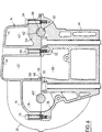
- the engine 10 essentially consists of a cylinder block 12 surmounted by a cylinder head 14 covered by a cylinder head cover 16.
- the cylinder head is supplied with intake air by an intake device 20 comprising an air distribution unit 22 to which are connected an inlet tube 24 equipped with a throttle valve 26 and tubular conduits of suction 28, the outputs of which are connected to the intake pipes (not shown) formed in the cylinder head 14.
- an intake device 20 comprising an air distribution unit 22 to which are connected an inlet tube 24 equipped with a throttle valve 26 and tubular conduits of suction 28, the outputs of which are connected to the intake pipes (not shown) formed in the cylinder head 14.
- FIGS. 1 and 2 also recognize the fuel injectors 30 and an air filter 32.
- the cylinder head cover 16 has the function only of closing the upper face of the cylinder head while protecting the rotating moving parts such as the camshafts and / or rocker linkages.
- Each cylinder is connected to the air intake device by three intake valves and to the exhaust by two exhaust valves.
- the two intake valves 34 are controlled by a first camshaft 40 while the intake valve 36 and the two exhaust valves 38 are controlled by a second camshaft 42.
- the axes of rotation of the camshafts 40 and 42 are parallel to the line of the cylinder heads of the cylinder head.
- the cylinder head 14 has a lower face 44 designed to cooperate with the upper face of the cylinder block 12 with the interposition of a cylinder head gasket, the combustion chamber 46 of each cylinder being formed at least partially in this lower face 44.
- the cylinder head 14 has a flat upper face 48 parallel to the lower face 44 which cooperates with the lower face 50 of the cylinder head cover 16.
- the cylinder head 14 is fixed to the engine block 12 by a series of screws 52 while the cylinder head cover 16 is fixed to the cylinder head 14 by a series of screws 54.
- the cylinder head cover 16 is delimited externally by a wall 56 and divided internally by several partitions 58 and 60 which extend parallel to the line of the cylinders.
- the internal space or compartment 62 essentially delimited by the external wall 56 and by the partitions 58 and 60 constitutes the major part of the distribution box for the intake air between the long intake ducts 28 or the ducts short admission 66.
- the intake box is completed by a cell 68 formed in the upper face 48 of the cylinder head 14 which faces the space 62 of the cover 16.
- the short intake duct of the intake valve 36 is in fact constituted by a portion of intake manifold 66 formed in the cylinder head 14 and which opens into the cavity 68.
- Each long intake duct 28 is formed in the cylinder head cover 16, is connected to the internal space 62 of this cover and opens into a long intake manifold 72 formed in the cylinder head 14.
- the entire air intake device is therefore integrated into the upper part of the engine.
- the partitions 58 and 60 and the outer wall 56 of the cover 16 also delimit two chambers 74 and 76 which receive the camshafts 40 and 42.
- Rooms 74 and 76 are completed by complementary cells 78 and 80 formed in the upper face 48 of the cylinder head 14.
- the chambers 74 and 76 are isolated from the distribution box 62 by the transverse partitions 82 and 84 which delimit them and in which upper half-bearings 86 and 88 are formed respectively which cooperate with corresponding lower half-bearings 90 and 92 to ensure the rotational mounting of the camshafts 40 and 42 on the cylinder head 14.
- the assembly consisting of the cylinder head 14 and the cover 16 also performs the rotational mounting of the moving parts of the cylinder head.
- a spark plug 91 is mounted in a cylindrical hole 93 in the cylinder head 14 which is extended by a corresponding hole 94 formed in the cover 16.
- Injectors 96 are mounted laterally on the cylinder head 14 in injection conduits 98 which open in the vicinity of the heads of the valves 34 at the lower end of the long intake pipes 72.
- the upper half-bearings 86 and 88 provided for receiving the camshafts are not formed directly in the cover 16 but in the caps of independent bearings 100 and 102 which are themselves located in rooms 74 and 76.
- the invention is of course not limited to the embodiment which has just been described, the number of valves of each cylinder possibly being different, for example, as can the control of the intake, applications of the invention n not being limited to overhead camshaft engines.
Landscapes
- Engineering & Computer Science (AREA)
- Chemical & Material Sciences (AREA)
- Combustion & Propulsion (AREA)
- Mechanical Engineering (AREA)
- General Engineering & Computer Science (AREA)
- Physics & Mathematics (AREA)
- Geometry (AREA)
- Cylinder Crankcases Of Internal Combustion Engines (AREA)
Applications Claiming Priority (2)
| Application Number | Priority Date | Filing Date | Title |
|---|---|---|---|
| FR9010075A FR2665730B1 (fr) | 1990-08-07 | 1990-08-07 | Moteur a combustion interne a dispositif d'admission d'air integre dans la culasse. |
| FR9010075 | 1990-08-07 |
Publications (2)
| Publication Number | Publication Date |
|---|---|
| EP0470874A1 true EP0470874A1 (de) | 1992-02-12 |
| EP0470874B1 EP0470874B1 (de) | 1994-04-06 |
Family
ID=9399487
Family Applications (1)
| Application Number | Title | Priority Date | Filing Date |
|---|---|---|---|
| EP91401889A Expired - Lifetime EP0470874B1 (de) | 1990-08-07 | 1991-07-08 | Brennkraftmaschine mit Lufteinlasseinrichtung integriert in einem Zylinderkopf |
Country Status (3)
| Country | Link |
|---|---|
| EP (1) | EP0470874B1 (de) |
| DE (1) | DE69101607T2 (de) |
| FR (1) | FR2665730B1 (de) |
Cited By (5)
| Publication number | Priority date | Publication date | Assignee | Title |
|---|---|---|---|---|
| EP0645523A1 (de) * | 1993-09-22 | 1995-03-29 | Dr.Ing.h.c. F. Porsche Aktiengesellschaft | Brennkraftmaschine |
| EP0798450A1 (de) * | 1996-03-25 | 1997-10-01 | Toyota Jidosha Kabushiki Kaisha | Brennkraftmaschine mit einer elektromagnetischen Betätigungsvorrichtung für die Hubventile und Zylinderkopfstrukturen desselben |
| GB2347465A (en) * | 1999-03-01 | 2000-09-06 | Ford Global Tech Inc | I.c. engine plenum/runner module having integrated engine valve cover |
| CN103452713A (zh) * | 2012-05-31 | 2013-12-18 | Tvs电机股份有限公司 | 单汽缸内燃机的进气系统 |
| FR3077092A1 (fr) * | 2018-01-24 | 2019-07-26 | Renault S.A.S. | Circuit d’admission d’air optimisee d’un groupe motopropulseur de vehicule |
Families Citing this family (4)
| Publication number | Priority date | Publication date | Assignee | Title |
|---|---|---|---|---|
| DE102008062188A1 (de) * | 2008-12-13 | 2010-06-17 | Volkswagen Ag | Zylinderkopf mit einem Saugrohrflansch |
| JP5481283B2 (ja) * | 2010-06-11 | 2014-04-23 | 本田技研工業株式会社 | 内燃機関のシリンダヘッド構造 |
| DE102011076001A1 (de) * | 2011-05-17 | 2012-11-22 | Elringklinger Ag | Haube für einen Motorblock |
| CN105569868A (zh) * | 2015-12-14 | 2016-05-11 | 中国北方发动机研究所(天津) | 一种新型高效进气系统 |
Citations (5)
| Publication number | Priority date | Publication date | Assignee | Title |
|---|---|---|---|---|
| GB191327591A (en) * | 1913-12-01 | 1914-07-02 | Albion Motor Car Co Ltd | Improvements in connection with "Monobloc" Four Cylinder Internal Combustion Engines. |
| GB122468A (en) * | 1918-01-23 | 1919-01-23 | Albion Motor Car Co Ltd | Improvements in the Induction Passages of Internal Combustion Engines. |
| EP0293278A1 (de) * | 1987-05-29 | 1988-11-30 | Regie Nationale Des Usines Renault | Multiventil-Zylinderkopf für Brennkraftmaschine |
| EP0307571A2 (de) * | 1987-09-14 | 1989-03-22 | Dr.Ing.h.c. F. Porsche Aktiengesellschaft | Zylinderkopfhaube mit Saugrohranlage für eine Brennkraftmaschine |
| EP0309418A2 (de) * | 1987-09-23 | 1989-03-29 | FIAT AUTO S.p.A. | Zylinderkopf für eine Brennkraftmaschine |
-
1990
- 1990-08-07 FR FR9010075A patent/FR2665730B1/fr not_active Expired - Fee Related
-
1991
- 1991-07-08 DE DE69101607T patent/DE69101607T2/de not_active Expired - Fee Related
- 1991-07-08 EP EP91401889A patent/EP0470874B1/de not_active Expired - Lifetime
Patent Citations (5)
| Publication number | Priority date | Publication date | Assignee | Title |
|---|---|---|---|---|
| GB191327591A (en) * | 1913-12-01 | 1914-07-02 | Albion Motor Car Co Ltd | Improvements in connection with "Monobloc" Four Cylinder Internal Combustion Engines. |
| GB122468A (en) * | 1918-01-23 | 1919-01-23 | Albion Motor Car Co Ltd | Improvements in the Induction Passages of Internal Combustion Engines. |
| EP0293278A1 (de) * | 1987-05-29 | 1988-11-30 | Regie Nationale Des Usines Renault | Multiventil-Zylinderkopf für Brennkraftmaschine |
| EP0307571A2 (de) * | 1987-09-14 | 1989-03-22 | Dr.Ing.h.c. F. Porsche Aktiengesellschaft | Zylinderkopfhaube mit Saugrohranlage für eine Brennkraftmaschine |
| EP0309418A2 (de) * | 1987-09-23 | 1989-03-29 | FIAT AUTO S.p.A. | Zylinderkopf für eine Brennkraftmaschine |
Cited By (10)
| Publication number | Priority date | Publication date | Assignee | Title |
|---|---|---|---|---|
| EP0645523A1 (de) * | 1993-09-22 | 1995-03-29 | Dr.Ing.h.c. F. Porsche Aktiengesellschaft | Brennkraftmaschine |
| US5515827A (en) * | 1993-09-22 | 1996-05-14 | Dr. Ing. H.C.F. Porsche Ag | Multicylinder, four-stroke internal-combustion engine having three intake valves and one exhaust valve per cylinder |
| EP0798450A1 (de) * | 1996-03-25 | 1997-10-01 | Toyota Jidosha Kabushiki Kaisha | Brennkraftmaschine mit einer elektromagnetischen Betätigungsvorrichtung für die Hubventile und Zylinderkopfstrukturen desselben |
| US5720242A (en) * | 1996-03-25 | 1998-02-24 | Toyota Jidosha Kabushiki Kaisha | Internal combustion engine equipped with an electromagnetic valve driving apparatus and head structure thereof |
| GB2347465A (en) * | 1999-03-01 | 2000-09-06 | Ford Global Tech Inc | I.c. engine plenum/runner module having integrated engine valve cover |
| GB2347465B (en) * | 1999-03-01 | 2003-06-25 | Ford Global Tech Inc | Plenum/runner module having integrated engine valve cover |
| CN103452713A (zh) * | 2012-05-31 | 2013-12-18 | Tvs电机股份有限公司 | 单汽缸内燃机的进气系统 |
| CN103452713B (zh) * | 2012-05-31 | 2016-03-30 | Tvs电机股份有限公司 | 单汽缸内燃机的进气系统 |
| FR3077092A1 (fr) * | 2018-01-24 | 2019-07-26 | Renault S.A.S. | Circuit d’admission d’air optimisee d’un groupe motopropulseur de vehicule |
| WO2019145212A1 (fr) * | 2018-01-24 | 2019-08-01 | Renault S.A.S | Circuit d'admission d'air optimisee d'un groupe motopropulseur de vehicule |
Also Published As
| Publication number | Publication date |
|---|---|
| DE69101607T2 (de) | 1994-11-10 |
| FR2665730A1 (fr) | 1992-02-14 |
| FR2665730B1 (fr) | 1993-08-06 |
| EP0470874B1 (de) | 1994-04-06 |
| DE69101607D1 (de) | 1994-05-11 |
Similar Documents
| Publication | Publication Date | Title |
|---|---|---|
| EP0470874B1 (de) | Brennkraftmaschine mit Lufteinlasseinrichtung integriert in einem Zylinderkopf | |
| EP0448431B1 (de) | Einlass- und Ölabscheidevorrichtung für eine Brennkraftmaschine und Maschine versehen mit dieser Vorrichtung | |
| JPH06264757A (ja) | V型エンジンの吸排気構造 | |
| EP0565410B1 (de) | Integrierte Rampenvorrichtung für die Abgasrückführung einer Brennkraftmaschine | |
| EP0293278B1 (de) | Multiventil-Zylinderkopf für Brennkraftmaschine | |
| EP0463267A1 (de) | Einlassvorrichtung für Brennkraftmaschine | |
| EP0846223B2 (de) | Ansaugkrümmer für brennkraftmaschine | |
| FR2783567A1 (fr) | Collecteur d'admission pour moteur a combustion interne | |
| EP3971510B1 (de) | Wärmebehandlungsmodul für verbrennungsmotor | |
| FR2765629A1 (fr) | Moteur a injection directe et allumage commande | |
| EP0209426B1 (de) | Zylinderkopf einer Brennkraftmaschine mit drei Ventilen pro Zylinder | |
| EP0666417B1 (de) | Anordnung eines Kraftstoffeinspritzmotors mit belüfteten Einspritzdüsen | |
| EP2299100B1 (de) | Saugrohr mit integrierter Kurbelgehäuseentlüftung und Fahrzeug mit einem solchen Saugrohr | |
| FR2763646A1 (fr) | Moteur a injection directe et allumage commande | |
| FR2912784A1 (fr) | Moteur a combustion interne comportant un repartiteur d'admission d'air et procede de fabrication d'un tel repartiteur | |
| EP0983426B1 (de) | Brennkraftmaschine mit fremdzündung | |
| FR2848612A1 (fr) | Filtre a air pour moteur a combustion interne, et moteur equipe dudit filtre | |
| EP3480439A1 (de) | Luftzufuhrkreislauf für motor mit gesteuerter zündung mit einer im zylinderkopf integrierten druckkammer | |
| EP0251835A1 (de) | Zylinderkopf für eine Brennkraftmaschine mit drei Ventilen pro Zylinder und mit hohem Druck in den Zylindern | |
| FR2857417A1 (fr) | Circuit d'admission pour moteur suralimente a filtre a particules | |
| FR2778694A1 (fr) | Moteur a combustion interne a allumage commande et a injection directe | |
| EP1431541A1 (de) | Brennkraftmaschine mit Mitteln zur Variation der Drallintensität | |
| FR3074537A1 (fr) | Culasse d'un vehicule automobile comprenant un collecteur d'echappement integre | |
| FR2864166A1 (fr) | Moteur a combustion interne avec stratification de gaz d'echappement recycles et procede de stratification | |
| FR2731045A1 (fr) | Dispositif de commande de l'alimentation d'un moteur a combustion interne |
Legal Events
| Date | Code | Title | Description |
|---|---|---|---|
| PUAI | Public reference made under article 153(3) epc to a published international application that has entered the european phase |
Free format text: ORIGINAL CODE: 0009012 |
|
| 17P | Request for examination filed |
Effective date: 19911019 |
|
| AK | Designated contracting states |
Kind code of ref document: A1 Designated state(s): DE GB IT |
|
| 17Q | First examination report despatched |
Effective date: 19930316 |
|
| GRAA | (expected) grant |
Free format text: ORIGINAL CODE: 0009210 |
|
| AK | Designated contracting states |
Kind code of ref document: B1 Designated state(s): DE GB IT |
|
| REF | Corresponds to: |
Ref document number: 69101607 Country of ref document: DE Date of ref document: 19940511 |
|
| GBT | Gb: translation of ep patent filed (gb section 77(6)(a)/1977) |
Effective date: 19940419 |
|
| ITF | It: translation for a ep patent filed | ||
| PLBE | No opposition filed within time limit |
Free format text: ORIGINAL CODE: 0009261 |
|
| STAA | Information on the status of an ep patent application or granted ep patent |
Free format text: STATUS: NO OPPOSITION FILED WITHIN TIME LIMIT |
|
| 26N | No opposition filed | ||
| PGFP | Annual fee paid to national office [announced via postgrant information from national office to epo] |
Ref country code: DE Payment date: 19960621 Year of fee payment: 6 |
|
| PGFP | Annual fee paid to national office [announced via postgrant information from national office to epo] |
Ref country code: GB Payment date: 19960702 Year of fee payment: 6 |
|
| PG25 | Lapsed in a contracting state [announced via postgrant information from national office to epo] |
Ref country code: GB Free format text: LAPSE BECAUSE OF NON-PAYMENT OF DUE FEES Effective date: 19970708 |
|
| GBPC | Gb: european patent ceased through non-payment of renewal fee |
Effective date: 19970708 |
|
| PG25 | Lapsed in a contracting state [announced via postgrant information from national office to epo] |
Ref country code: DE Free format text: LAPSE BECAUSE OF NON-PAYMENT OF DUE FEES Effective date: 19980401 |
|
| PG25 | Lapsed in a contracting state [announced via postgrant information from national office to epo] |
Ref country code: IT Free format text: LAPSE BECAUSE OF NON-PAYMENT OF DUE FEES;WARNING: LAPSES OF ITALIAN PATENTS WITH EFFECTIVE DATE BEFORE 2007 MAY HAVE OCCURRED AT ANY TIME BEFORE 2007. THE CORRECT EFFECTIVE DATE MAY BE DIFFERENT FROM THE ONE RECORDED. Effective date: 20050708 |