EP0470927A1 - Dispositif de protection sur une machine d'enroulage - Google Patents
Dispositif de protection sur une machine d'enroulage Download PDFInfo
- Publication number
- EP0470927A1 EP0470927A1 EP91810556A EP91810556A EP0470927A1 EP 0470927 A1 EP0470927 A1 EP 0470927A1 EP 91810556 A EP91810556 A EP 91810556A EP 91810556 A EP91810556 A EP 91810556A EP 0470927 A1 EP0470927 A1 EP 0470927A1
- Authority
- EP
- European Patent Office
- Prior art keywords
- winding machine
- door
- protective
- protective shield
- tree
- Prior art date
- Legal status (The legal status is an assumption and is not a legal conclusion. Google has not performed a legal analysis and makes no representation as to the accuracy of the status listed.)
- Withdrawn
Links
Images


Classifications
-
- D—TEXTILES; PAPER
- D02—YARNS; MECHANICAL FINISHING OF YARNS OR ROPES; WARPING OR BEAMING
- D02H—WARPING, BEAMING OR LEASING
- D02H11/00—Methods or apparatus not provided for in the preceding groups, e.g. for cleaning the warp
Definitions
- the invention relates to a protective device on a winding machine according to the preamble of claim 1.
- the purpose of such devices is to protect the operators from wind and dust.
- predominantly cotton threads are processed on slip machines, which are drawn off from the creel at a take-off speed of up to 1200 m / min.
- the various points of contact and deflection of the threads release fibers and protective particles which are thrown against the winding machine by the air flow.
- the protective device should increasingly increase the operational safety of the entire system. It has therefore already started to integrate the winding machine into a kind of partition which separates the operator side of the winding machine from the area of the creel.
- a protective device is known for example from DE-A-38 43 608.
- the protective shield is arranged separately from the winding machine on the operator side and surrounds the machine in such a way that the operators cannot accidentally get into the area of the rotating machine parts. Nevertheless, the winding machine remains freely accessible, as there is sufficient space between the winding machine and the protective shield.
- the door arranged in the protective shield allows quick access to the winding machine, which of course would also be possible from the open gate side.
- the protective shield also provides optimal noise protection, since the sound waves are reflected and / or absorbed against the gate side when the door is closed.
- the opening arrangement of the side wall sections is particularly advantageous in terms of flow technology, since in this way the flow is as laminar as possible without eddy formation.
- the protective shield has a base wall running approximately parallel to the tree, to which the lateral wall sections adjoin, and if a door is arranged in the center of the base wall.
- This base wall allows the arrangement of a sliding door that opens laterally.
- the protective shield could also have an approximately semicircular or parabolic configuration.
- the door is preferably arranged on the central axis creel / winding machine and has a maximum width which is somewhat larger than the maximum length of the tree. This is the easiest way to transport the finished product Guaranteed winding or the supply of empty trees in the winding machine.
- the door can be provided with drive and / or locking means which can be activated depending on the operating state of the winding machine in such a way that the door can only be opened when the winding machine is at a standstill or when it is crawling. This ensures that at the normal working speed of the winding machine, no one can approach the winding machine through the door.
- a sensor device can be arranged on the inside of the protective shield facing the winding machine, which is in operative connection with the winding machine in such a way that it cannot be activated if there is a Person in the area of the sensor device.
- the sensor device can e.g. a light barrier arrangement running approximately parallel to the tree.
- the sensor device could also be an electronic camera, an infrared sensor or the like. Together with the sensor device, the protective shield forms a barrier to the immediate working area of the winding machine.
- a suction device is arranged on the protective shield according to the invention, preferably in the upper region above the door height on the inside.
- the protective shield can have corner cavities in which supply and disposal lines for the suction device are arranged.
- FIG. 1 shows a winding system, for example a slip system of a type known per se, with the winding machine 1 and the creel 3.
- the creel 3 is designed as a so-called V-gate, but any other coil creel can also be used could come.
- the thread sheet 4 is drawn off from the creel in the direction of arrow A and wound onto the tree 2 of the winding machine 1.
- auxiliary devices not shown here, such as e.g. Thread tensioner, thread monitor, slip comb, deflection and press rollers etc., for use.
- a two-leaf sliding door 7 is arranged in the center of the base wall 8. But it could easily be a double door.
- the sliding door is preferably made transparent so that the working process on the winding machine can be observed through it.
- the sliding door is e.g. pneumatic drive means 9 opened and closed or locked.
- the drive means 9 can only be activated as a function of the operating state of the winding machine 1. At normal operating speed of the winding machine, the sliding door 7 remains closed. Opening is only possible when the machine is at a standstill or when the machine is operating in slow crawl.
- the drive means 9 automatically open the sliding door if the winding machine is damaged by an operating fault, e.g. by a thread break, is shut down, or when the winding process is finished.
- a suction device 11 On the inside of the protective shield 5 above the door 7 there is a suction device 11 which sucks off the dust and dirt particles brought in in the direction of the arrow A.
- the suction device can additionally be provided with hose pieces 12 with which inaccessible places or poorly flushed places of the winding machine 1 can be cleaned.
- the suction device 11 can be combined with a filter device in which the suctioned air is cleaned immediately.
- the protective shield can be made of metal, wood or a plastic material. Obviously, it can be particularly advantageously retrofitted to existing winding systems.
- the inside of the protective shield could advantageously be covered with a sound-absorbing material.
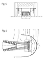
- Figure 6 shows an alternative embodiment in which the protective shield 5 is semicircular in plan, the side wall portions 6 and 6 'still have a short straight piece.
- the door 7 is also designed as a two-leaf sliding door, the door leaves opening in an arc shape in the direction of arrow C.
- the suction device 11 is also adapted to the semicircular shape of the protective shield.
- the sliding door 7 opens up to the small opening position 19.
- the door opens 7 to the maximum door opening 20. This door opening makes it possible to roll the completely wound tree onto the outside of the protective shield. An empty tree is then rolled up in the direction of arrow B and introduced into the winding machine 1.
- the function of the suction device 11 can also be coupled to the operating state of the winding machine. If the winding process is interrupted or the door opening 19 is small, the suction device can continue to operate, while if the winding process ends or the door opening 20 is maximal, the suction device is also shut down. As soon as the door 7 is opened manually or automatically by a switching process, the sensor device 10 is also automatically switched off.
Landscapes
- Engineering & Computer Science (AREA)
- Textile Engineering (AREA)
- Operating, Guiding And Securing Of Roll- Type Closing Members (AREA)
Applications Claiming Priority (2)
| Application Number | Priority Date | Filing Date | Title |
|---|---|---|---|
| CH2563/90 | 1990-08-06 | ||
| CH256390 | 1990-08-06 |
Publications (1)
| Publication Number | Publication Date |
|---|---|
| EP0470927A1 true EP0470927A1 (fr) | 1992-02-12 |
Family
ID=4236622
Family Applications (1)
| Application Number | Title | Priority Date | Filing Date |
|---|---|---|---|
| EP91810556A Withdrawn EP0470927A1 (fr) | 1990-08-06 | 1991-07-11 | Dispositif de protection sur une machine d'enroulage |
Country Status (1)
| Country | Link |
|---|---|
| EP (1) | EP0470927A1 (fr) |
Cited By (2)
| Publication number | Priority date | Publication date | Assignee | Title |
|---|---|---|---|---|
| DE4310946A1 (de) * | 1992-05-19 | 1993-11-25 | Benninger Ag Maschf | Wickelmaschine, insbesondere Zettel- oder Schärmaschine |
| DE4310921A1 (de) * | 1992-05-19 | 1993-11-25 | Benninger Ag Maschf | Schutzvorrichtung an einer Wickelmaschine |
Citations (4)
| Publication number | Priority date | Publication date | Assignee | Title |
|---|---|---|---|---|
| US3378998A (en) * | 1965-12-03 | 1968-04-23 | Shackelford John Cooper | Air handling and cleaning apparatus for machines |
| US3667093A (en) * | 1970-01-02 | 1972-06-06 | Clifford Culpepper Jr | Method and apparatus for cleaning a textile creel and winding apparatus |
| DE3843608A1 (de) * | 1988-01-22 | 1989-07-27 | Benninger Ag Maschf | Schutzvorrichtung gegen wind und staub an einer wickelmaschine |
| DE3901488A1 (de) * | 1988-02-05 | 1989-08-17 | Benninger Ag Maschf | Wickelmaschine mit reduziertem faden-laufwiderstand und verfahren zur reduzierung des laufwiderstands |
-
1991
- 1991-07-11 EP EP91810556A patent/EP0470927A1/fr not_active Withdrawn
Patent Citations (4)
| Publication number | Priority date | Publication date | Assignee | Title |
|---|---|---|---|---|
| US3378998A (en) * | 1965-12-03 | 1968-04-23 | Shackelford John Cooper | Air handling and cleaning apparatus for machines |
| US3667093A (en) * | 1970-01-02 | 1972-06-06 | Clifford Culpepper Jr | Method and apparatus for cleaning a textile creel and winding apparatus |
| DE3843608A1 (de) * | 1988-01-22 | 1989-07-27 | Benninger Ag Maschf | Schutzvorrichtung gegen wind und staub an einer wickelmaschine |
| DE3901488A1 (de) * | 1988-02-05 | 1989-08-17 | Benninger Ag Maschf | Wickelmaschine mit reduziertem faden-laufwiderstand und verfahren zur reduzierung des laufwiderstands |
Non-Patent Citations (1)
| Title |
|---|
| TEXTIL-PRAXIS INTERNATIONAL Bd. 38, Nr. 2, 1. Februar 1983, LEINFELDEN ,D Seiten 125 - 133; L. NEUHAUS: 'Möglichkeiten zur Verringerung der Staubentwicklung beim Spulen und Zetteln ' * |
Cited By (4)
| Publication number | Priority date | Publication date | Assignee | Title |
|---|---|---|---|---|
| DE4310946A1 (de) * | 1992-05-19 | 1993-11-25 | Benninger Ag Maschf | Wickelmaschine, insbesondere Zettel- oder Schärmaschine |
| DE4310921A1 (de) * | 1992-05-19 | 1993-11-25 | Benninger Ag Maschf | Schutzvorrichtung an einer Wickelmaschine |
| DE4310921C2 (de) * | 1992-05-19 | 1998-07-02 | Benninger Ag Maschf | Schutzvorrichtung an einer Wickelmaschine |
| DE4310946C2 (de) * | 1992-05-19 | 2001-05-31 | Benninger Ag Maschf | Wickelmaschine, insbesondere Zettel- oder Schärmaschine |
Similar Documents
| Publication | Publication Date | Title |
|---|---|---|
| DE19616483C2 (de) | Werkzeugmaschine mit einer Schiebetür | |
| DE19713747A1 (de) | Verfahren und Vorrichtung zum Ausfiltern von Fasern aus einem Luftstrom | |
| EP3165635B1 (fr) | Dispositif d'étirage | |
| DE2947755C2 (fr) | ||
| DE3843608C2 (fr) | ||
| EP0470927A1 (fr) | Dispositif de protection sur une machine d'enroulage | |
| EP0678336A2 (fr) | Cabine de poudrage | |
| DE3734568C2 (fr) | ||
| DE1510727C3 (de) | Pneumatische Reimgungsvorrich tung an Textilmaschinen | |
| LU84052A1 (de) | Einwurftuer fuer eine ballenpresse | |
| DE2528756B2 (de) | Verfahren und Vorrichtung zum Entfernen von Abfällen unter einer Karde | |
| DE10250293B4 (de) | Vorrichtung zum Reinigen eines Filters einer Offenend-Spinnmaschine | |
| DE2814345C2 (de) | Vorrichtung an einem Tor, vorzugsweise für Industriegebäude | |
| DE4310921C2 (de) | Schutzvorrichtung an einer Wickelmaschine | |
| DE4310946C2 (de) | Wickelmaschine, insbesondere Zettel- oder Schärmaschine | |
| DE3235161C2 (de) | Vorrichtung zum Scheren von Stoffbahnen | |
| DE19851020A1 (de) | Strecke | |
| EP1160500B1 (fr) | Dispositif d'écran | |
| EP0461411A1 (fr) | Dispositif de protection de la poussière pour un enrouleur | |
| DE8532355U1 (de) | Trocknungsvorrichtung für die Trocknung von Kraftfahrzeugen in Fahrzeugwaschanlagen | |
| DE3426012A1 (de) | Vorrichtung zum entfernen des faserpflugs von einem sieb | |
| DE20303138U1 (de) | Abzug mit einem Gehäuse, das einen Innenraum aufweist | |
| DE2601016C2 (de) | Verfahren und Einrichtung zum Reinigen von Filterkästen | |
| DE3527920C2 (fr) | ||
| DE202018106912U1 (de) | Beweglicher Laufsteg für einen Zellstofftrockner und ein Zellstofftrockner |
Legal Events
| Date | Code | Title | Description |
|---|---|---|---|
| PUAI | Public reference made under article 153(3) epc to a published international application that has entered the european phase |
Free format text: ORIGINAL CODE: 0009012 |
|
| AK | Designated contracting states |
Kind code of ref document: A1 Designated state(s): CH DE ES FR IT LI |
|
| STAA | Information on the status of an ep patent application or granted ep patent |
Free format text: STATUS: THE APPLICATION IS DEEMED TO BE WITHDRAWN |
|
| 18D | Application deemed to be withdrawn |
Effective date: 19920813 |