EP0470971B1 - Aufnahme- und/oder wiedergabegerät für berührungslos abtastbare rotierende aufzeichnungsträger - Google Patents
Aufnahme- und/oder wiedergabegerät für berührungslos abtastbare rotierende aufzeichnungsträger Download PDFInfo
- Publication number
- EP0470971B1 EP0470971B1 EP90906209A EP90906209A EP0470971B1 EP 0470971 B1 EP0470971 B1 EP 0470971B1 EP 90906209 A EP90906209 A EP 90906209A EP 90906209 A EP90906209 A EP 90906209A EP 0470971 B1 EP0470971 B1 EP 0470971B1
- Authority
- EP
- European Patent Office
- Prior art keywords
- counter
- recording
- braking
- rotational speed
- recording medium
- Prior art date
- Legal status (The legal status is an assumption and is not a legal conclusion. Google has not performed a legal analysis and makes no representation as to the accuracy of the status listed.)
- Expired - Lifetime
Links
Images


Classifications
-
- G—PHYSICS
- G11—INFORMATION STORAGE
- G11B—INFORMATION STORAGE BASED ON RELATIVE MOVEMENT BETWEEN RECORD CARRIER AND TRANSDUCER
- G11B19/00—Driving, starting, stopping record carriers not specifically of filamentary or web form, or of supports therefor; Control thereof; Control of operating function ; Driving both disc and head
- G11B19/20—Driving; Starting; Stopping; Control thereof
- G11B19/22—Brakes other than speed-regulating brakes
Definitions
- the invention relates to a recording and / or reproducing device for contactlessly scanned rotating recording media.
- Devices of this type for example CD players or video record players, are equipped with a loading and unloading device into which the record carrier, a CD disk or a video disk, is inserted by hand and from which it can be removed again by hand. After insertion, the CD disk is automatically brought into the play position. Using a so-called STOP button, the operator of the CD player can interrupt the playing of a CD at any time. The CD disk is stopped and automatically brought into the removal position so that the operator can remove it from the loading device, for example in order to be able to insert another CD disk.
- a loading and unloading device into which the record carrier, a CD disk or a video disk, is inserted by hand and from which it can be removed again by hand. After insertion, the CD disk is automatically brought into the play position. Using a so-called STOP button, the operator of the CD player can interrupt the playing of a CD at any time. The CD disk is stopped and automatically brought into the removal position so that the operator can remove it from the loading device, for example in order to
- a test report on two CD players of the so-called drawer type is published on pages 50 to 54 of Funkschau 10, May 1985.
- the loading and unloading device is designed as a drawer that is moved from the front of the CD player for inserting and removing a CD disk.
- the CD players assessed in the above test report are also equipped with the STOP button mentioned.
- the speed of a CD disk is not constant, however, because a CD player is a system that, unlike a CAV system, the abbreviation for Constant Angular Velocity, is not like the angular one, but as with a CLV system - the abbreviation for constant linear velocity - usually keeps the path speed constant.
- the CD disk is still rotating during the unloading process, either in the direction of play or even backwards, depending on whether it has been braked too little or too much by the motor of the disk drive.
- the sensitive surface of a CD disk that is still rotating during the automatic unloading process can easily be damaged.
- FR-A 2470506 it is known to apply a brake signal with a fixed value to the motor of the disk drive in order to e.g. of a video turntable.
- a measuring device measures the speed of the disk during braking. As soon as the plate has reached a predetermined speed, e.g. zero, braked, the braking process is ended.
- the invention solves this problem in that the braking energy required to stop the rotating record carrier is also generated as a function of the diameter of the record carrier.
- the braking of the rotating recording medium can be done, for example, by means of one or more braking pulses which are applied to the motor of the Plate drive are placed.
- the duration and / or the amplitude of the braking pulses depend on the speed of the recording medium, which can be determined, for example, by means of a mark and a photosensor.
- the speed of the recording medium which can be determined, for example, by means of a mark and a photosensor.
- the speed of the disc from the subcode, which contains information about the so-called cumulative playing time.
- Each accumulated play time which is often also referred to as A-time, includes a certain speed of the CD or video disc.
- the initial speed when reading the innermost data track is 500 rpm.
- the initial speed of 500 rpm when reading the innermost data track drops linearly to the final speed of 215 rpm, which is prescribed for reading the data from the outermost data track.
- the initial speed for the video section is 2700 rpm, while the CDV disk only rotates at 2000 rpm when reading the outermost data track of the video section.
- the speed can therefore either be between 500 rpm and 200 rpm or between 2700 rpm and 2000 rpm, depending on whether the audio part or the video part is played.
- a CDV disk should always be braked to a standstill for removal.
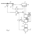
- FIG. 1 shows an arrangement in which the braking pulses for the motor of the disk drive are generated as a function of the instantaneous speed of a CD disk.
- a CD disk CD which is driven by a motor M
- data is read by means of an optical scanning device AV and fed to a decoder D.
- the decoder D outputs the audio signal at its first output A1.
- the decoder D outputs the control signals for the controllers FT of the focus and tracking control loop.
- the third output A3, at which the decoder D outputs the control signal for the disk speed, is connected via a switch S1 to the speed controller MR of the motor M.
- the fourth output A4 of the decoder D, at which the subcode can be removed, is connected to an evaluation circuit SC, the output of which is connected to the input of a counter Z1.
- the evaluation circuit SC delivers counting pulses for the counter Z1 which correspond to the accumulated playback time. If the CD is played from the beginning, the evaluation circuit SC sets the counter reading of the counter Z1 to zero and then emits counting pulses, so that the respective counter reading is always a measure of the cumulative playing time and thus also of the current disk speed.
- the evaluation circuit SC recognizes the accumulated playing time from the subcode; this is the time after which the seventh piece of music begins to play from the beginning.
- the evaluation circuit SC now loads the counter Z1 to the counter reading, which corresponds to the accumulated playing time for the seventh piece of music.
- the evaluation circuit SC updates the counter reading each time. The counter reading is therefore always proportional to the speed of rotation of the CD disk.
- the outputs of the counter Z1 are connected to the inputs of a ROM R1, the outputs of which are connected to a shift register SR.
- the output of the shift register SR is connected to the speed controller MR of the motor M via a switch S2.
- the stop input of the counter Z1 can be connected to the positive pole of a voltage source via a switch S3.
- switch S1 As long as the CD is being played, switch S1 is closed, but switches S2 and S3 are open. If the operator now wants to remove the inserted CD disk from the CD player, switches S2 and S3 are closed at the same time as the so-called STOP button is pressed, while switch S1 is opened.
- the counter Z1 is stopped by closing the switch S3.
- Its counter reading now serves as an address for the ROM R1, in which various bit patterns are stored.
- the bit pattern belonging to the counter reading is now given as a single brake pulse or a sequence of several brake pulses to the speed controller MR of the motor M in order to bring the CD disk with the correctly metered braking energy to a standstill quickly and reliably.
- the bit patterns stored in the ROM R1, which define the length and number of braking pulses, can e.g. be determined empirically.
- a second ROM R2 is now provided.
- the output of the counter Z1 can be connected to the input of the first ROM R1 or the second ROM R2 by means of a switch US, as shown in FIG. 2.
- the outputs of the two ROM R1 and R2 are connected to the inputs of an OR gate O, at the output of which the braking pulses for the speed controller MR of the motor M of the disk drive can be removed.
- the bit patterns for a normal CD disk are stored in the first ROM R1
- the bit patterns for a mini CD are stored in the second ROM R1. Switching from the first to the second ROM and vice versa can be done either manually or automatically.
- the diameter of the CD disk CD can be determined, for example, by means of a light barrier from an optical transmitter OS and an optical receiver OE.
- the mass of the plate is therefore also taken into account in addition to the rotational speed.
- a test brake pulse is applied to the motor M, which is dimensioned such that the CD disk CD is braked, but the data reproduction is not affected thereby.
- the speeds before and after the test brake pulse are measured and compared with one another. The comparison now serves as the basis for determining the duration of the braking pulses.
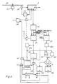
- the CD disk CD is driven by the motor M, the speed of which is regulated by the speed controller MR.
- the optical scanning device AV supplies the data signal to the decoder D, at whose output A1 the audio signal can be taken off, whose output A2 with the controllers FT of the focus and tracking control loop, its output A3 via the switch S1 with the speed controller MR and its output A4 with the evaluation circuit SC is connected.
- the outputs of the evaluation circuit SC are connected to the counter Z1 and a counter Z2.
- Switch S2 can be used to apply a positive voltage to the stop input of counter Z1.
- the outputs of the counter Z1 are connected to a memory SP1 and a monoflop M1.
- the outputs of the counter Z2 are connected to the inputs of a memory SP2, the output of which are connected to a difference generator DF.
- the outputs of the memory SP1 are also connected to the difference former DF and to the ROM R1, the outputs of which are connected to the shift register SR.
- the output of the difference former DF is connected to the input of a comparator V, the first output of which is connected to a monoflop M2 and the second output of which is connected to a monoflop M3.
- the output of the monoflop M2 is with the first Input, the output of the monoflop M3 is connected to the second input of a NOR gate N and an OR gate O1.
- the output of the NOR gate N is connected to the first input of an AND gate U.
- the output of the monoflop M1 is connected to the first input of an OR gate O2, the stop input of the counter Z2 and, via an inverter I, to the second input of the AND gate U, the third input of which has a clock T.
- the output of the AND gate U is connected to the clock input of the shift register SR, the output of which is connected to the third input of the OR gate O1.
- the output of the OR gate O2, the second input of which is connected to the output of the AND gate U, is connected to the speed controller MR.
- the counter reading of the counter Z1 is constantly updated by the evaluation circuit, so that it is always proportional to the current disk speed.
- switch S1 When the operator presses the STOP button, as indicated in FIG. 5a, switch S1 is opened at the same time, switch S2 is closed. As a result, the counter Z1 is stopped and its counter reading is taken from the memory SP1. The speed before the test brake pulse is therefore stored in memory SP1. Because the monoflop M1 is also set for the time t 1, the motor M now receives a test brake pulse for the duration t 1, as shown in Figure 5b. At the same time, the shift register SR is blocked because of the inverter I and the AND gate U.
- the counter Z2 is stopped, but the counter reading corresponds to the reduced speed due to the test brake pulse.
- the counter reading of the counter Z2 is taken over by the memory SP2.
- the difference between the meter readings is in the difference generator DF of the two counters Z1 and Z2 are formed and compared in the comparator V with a predeterminable threshold value X.
- the time it takes for the difference former DF to form the difference between the two counter readings and the comparator V for the comparison is denoted by t z in FIGS. 5c and 5d.
- the monoflop M2 is set, otherwise the monoflop M3, whose time constant t3 is chosen to be smaller than the time constant t2 of the monoflop M2.
- the shift register SR is released, so that now, as in the first exemplary embodiment, one or more braking pulses are output to the motor M.
- the monoflop M2 or M3 tilts back to the stable starting position, whereby the shift register SR is blocked again by the AND gate U.
- FIG. 5c shows a braking pulse B which is emitted when the monoflop M3 is set.
- FIG. 5f shows a number of braking pulses BI which are emitted by the shift register SR as long as the monoflop M2 is set. While the Monoflop M2 or M3 is set, it is possible to deliver either only one longer braking pulse or several braking pulses of shorter duration.
- the one comparator V e.g. multiple comparators are provided to form multiple intervals.
- the comparator is used to determine the interval at which the difference formed by the difference former DF lies.
- a monoflop is then provided for each interval. The fact that the monoflop is always set, in whose interval the difference falls, different braking pulses are generated.
- the second counter Z2 can also be omitted in the third exemplary embodiment. After the memory SP1 the counter reading of the counter Z1 has taken over before the test brake pulse, the counter Z1 continues to count. At the end of the test brake pulse, the memory SP2 adopts the new counter reading of the counter Z1, which corresponds to the speed reduced by the test brake pulse.
- a third exemplary embodiment represents a combination of the arrangement shown in FIG. 1 and the first exemplary embodiment.
- the current counter reading of the counter Z1 which is proportional to the current speed of the disk, is compared with a predefinable threshold value. If the counter reading is below this threshold value - or in other words, the speed is below a threshold value - then the braking pulse or the braking pulses are generated by means of the ROM R1 and the shift register SR, as shown in FIG. 1.
- the speed is then also greater than or equal to a threshold value - then a test brake pulse is emitted first and then one or more brake pulses are generated using the monoflop M2 or M3 according to that shown in FIG. 2 Embodiment generated.
- the invention is e.g. suitable for CD players, video record players, CDV players, DRAW disc players or magneto-optical devices.
Landscapes
- Rotational Drive Of Disk (AREA)
- Optical Recording Or Reproduction (AREA)
- Recording Measured Values (AREA)
- Feeding And Guiding Record Carriers (AREA)
- Signal Processing For Digital Recording And Reproducing (AREA)
- Telephone Set Structure (AREA)
- Rotary Switch, Piano Key Switch, And Lever Switch (AREA)
Description
- Die Erfindung betrifft ein Aufnahme- und/oder Wiedergabegerät für berührungslos abtastbare rotierende Aufzeichnungsträger.
- Derartige Geräte, z.B. CD-Spieler oder Videoplattenspieler, sind mit einer Lade- und Entladevorrichtung ausgestattet, in die der Aufzeichnungsträger, eine CD-Platte oder eine Videoplatte, von Hand eingelegt und aus der er von Hand wieder entnommen werden kann. Nach dem Einlegen wird die CD-Platte automatisch in die Abspielposition gebracht. Mittels einer sogenannten STOP-Taste kann der Bediener des CD-Spielers jederzeit das Abspielen einer CD-Platte unterbrechen. Die CD-Platte wird angehalten und automatisch in die Entnahmeposition gebracht, damit sie der Bediener aus der Ladevorrichtung entnehmen kann, um z.B. eine andere CD-Platte einlegen zu können.
- In Funkschau 10, Mai 1985 ist auf Seite 50 bis 54 ein Testbericht über zwei CD-Spieler vom sogenannten Schubladentyp veröffentlicht. Die Lade- und Entladevorrichtung ist bei diesem Typ als Schublade ausgeführt, die zum Einlegen und zur Entnahme einer CD-Platte aus der Frontseite des CD-Spielers gefahren wird. Die in dem genannten Testbericht beurteilten CD-Spieler sind auch mit der erwähnten STOP-Taste ausgerüstet.
- Bevor jedoch die CD-Platte aus der Abspielposition in die Entnahmeposition gebracht wird, sollte sie vom Motor des Plattenantriebs möglichst bis zum Stillstand abgebremst werden, um Beschädigungen ihrer empfindlichen Oberfläche während des Entladevorgangs zu vermeiden.
- Die Drehzahl einer CD-Platte ist aber nicht konstant, weil es sich bei einem CD-Spieler um ein System handelt, das im Gegensatz zu einem CAV-System, der Abkürzung für Constant-Angular-Velocity, nicht die Winkel-, sondern wie bei einem CLV-System - der Abkürzung für Constant-Linear-Velocity - üblich die Bahngeschwindigkeit konstant hält.
- Es kann daher durchaus der Fall auftreten, daß sich die CD-Platte während des Entladevorgangs noch dreht, entweder in der Abspielrichtung oder sogar rückwärts, je nach dem, ob sie vom Motor des Plattenantriebs zu wenig oder zu stark abgebremst wurde. Wie bereits erwähnt kann aber die empfindliche Oberfläche einer CD-Platte, die sich während des automatischen Entladevorgangs noch dreht, leicht beschädigt werden.
- Um sicher zu stellen, daß die CD-Platte zu Beginn des Entladevorgangs tatsächlich still steht, sollte daher zwischen dem Abbremsen der CD-Platte und dem Entladevorgang eine kurze Wartezeit als zeitlicher Sicherheitsabstand vorgesehen werden, damit die CD-Platte auslaufen kann. Diese Maßnahme hat aber den Nachteil, daß sich der Entladevorgang verzögert.
- Aus der FR-A 2470506 ist es bekannt, ein Bremssignal mit einem festen Wert an den Motor des Plattenantriebs zu legen, um die Platte eines Plattenspielers z.B. eines Videoplattenspielers anzuhalten. Eine Meßvorrichtung mißt die Drehzahl der Platte während des Abbremsens. Sobald die Platte auf eine vorgegebene Drehzahl, z.B. null, abgebremst ist, wird der Bremsvorgang beendet.
- Es ist daher Aufgabe der Erfindung, ein Aufnahme- und/oder Wiedergabegerät für berührungslos abtastbare rotierende Aufzeichnungsträger so zu gestalten, daß der rotierende Aufzeichnungsträger zur Entnahme schnell und sicher bis zum Stillstand abgebremst wird.
- Die Erfindung löst diese Aufgabe dadurch, daß die zum Anhalten des rotierenden Aufzeichnungsträgers erforderliche Bremsenergie auch in Abhängigkeit vom Durchmesser des Aufzeichnungsträgers erzeugt wird.
- Es zeigen
- Figur 1
- eine Anordnung zur Erzeugung von Bremsimpulsen in Abhängigkeit von der Drehzahl des Aufzeichnungsträgers
- Figur 2
- ein Teil eines ersten Ausführungsbeispiels
- Figur 3
- das erste Ausführungsbeispiel mit einer Lichtschranke
- Figur 4
- ein zweites Ausführungsbeispiel
- Figur 5
- Impulsdiagramme zum zweiten Ausführungsbeispiel.
- Die Abbremsung des rotierenden Aufzeichnungsträgers kann z.B. mittels eines oder mehrerer Bremsimpulse, die an den Motor des Plattenantriebs gelegt werden, erfolgen. Die Dauer und/oder die Amplitude der Bremsimpulse hängen von der Drehzahl des Aufzeichnungsträgers ab, die sich z.B. mittels einer Marke und eines Photosensors ermitteln läßt. Bei CD-Spielern und Videoplattenspielern besteht außerdem die Möglichkeit, die Drehzahl der Platte aus dem Subcode, der Informationen über die sogenannte kumulierte Abspielzeit enthält, zu berechnen. Zu jeder kumulierten Abspielzeit, die häufig auch als A-Time bezeichnet wird, gehört eine bestimmte Drehzahl der CD-Platte oder der Videoplatte.
- Die Drehzahl n berechnet sich nach folgender Formel:

w₁ ist die Anfangsdrehzahl, w₂ die Enddrehzahl, T die gesamte Spielzeit der Platte und A die sogenannte kumulierte Abspielzeit. Bei einer CD-Platte beträgt die Anfangsdrehzahl beim Lesen der innersten Datenspur 500 U/min. Während des Abspielens einer CD-Platte sinkt die Anfangsdrehzahl von 500 U/min beim Lesen der innersten Datenspur linear auf die Enddrehzahl von 215 U/min ab, die zum Lesen der Daten von der äußersten Datenspur vorgeschrieben ist. Bei einer CDV-Platte, die neben einem Audioteil noch einen Videoteil enthält, beträgt die Anfangsdrehzahl für den Videoteil 2700 U/min, während sich die CDV-Platte beim Lesen der äußersten Datenspur des Videoteils nur noch mit 2000 U/min dreht. Bei einer CDV-Platte kann daher die Drehzahl entweder zwischen 500 U/min und 200 U/min betragen oder zwischen 2700 U/min oder 2000 U/min liegen, je nachdem ob der Audioteil oder der Videoteil abgespielt wird. Trotz dieser großen Drehzahlunterschiede sollte aber auch eine CDV-Platte zur Entnahme stets zum Stillstand abgebremst werden. - In der Figur 1 ist nun eine Anordnung gezeigt, bei der die Bremsimpulse für den Motor des Plattenantriebs in Abhängigkeit von der augenblicklichen Drehzahl einer CD-Platte erzeugt werden.
- Von einer CD-Platte CD, die von einem Motor M angetrieben wird, werden mittels einer optischen Abtastvorrichtung AV Daten gelesen und einem Decoder D zugeführt. An seinem ersten Ausgang A1 gibt der Decoder D das Audiosignal ab. An seinem zweiten Ausgang A2 gibt der Decoder D die Regelsignale für die Regler FT des Fokus- und Spurregelkreises ab. Der dritte Ausgang A3, an dem der Decoder D das Regelsignal für die Plattendrehzahl abgibt, ist über einen Schalter S1 mit dem Drehzahlregler MR des Motors M verbunden. Der vierte Ausgang A4 des Decoders D, an dem der Subcode abnehmbar ist, ist mit einer Auswerteschaltung SC verbunden, deren Ausgang mit dem Eingang eines Zählers Z1 verbunden ist.
- Die Auswerteschaltung SC liefert für den Zähler Z1 Zählimpulse, die der kumulierten Abspielzeit entsprechen. Wird die CD-Platte von Anfang an abgespielt, so setzt die Auswerteschaltung SC den Zählerstand des Zählers Z1 auf null und gibt anschließend Zählimpulse ab, so daß der jeweilige Zählerstand stets ein Maß für die kumulierte Abspielzeit und somit auch für die augenblickliche Plattendrehzahl ist.
- Wird aber die CD- Platte nicht von Anfang an, sondern z.B. erst vom siebten Musikstück an abgespielt, so erkennt die Auswerteschaltung SC am Subcode die kumulierte Abspielzeit; das ist die Zeit nach der das siebte Musikstück beim Abspielen von Anfang an gerechnet beginnt. Die Auswerteschaltung SC lädt nun den Zähler Z1 auf den Zählerstand, welcher der kumulierten Abspielzeit für das siebte Musikstück entspricht. Beim Spurspringen von einem Musikstück zu einem anderen aktualisiert die Auswerteschaltung SC jedesmal den Zählerstand. Der Zählerstand ist daher stets proportional zur Umdrehungsgeschwindigkeit der CD-Platte.
- Die Ausgänge des Zählers Z1 sind mit den Eingängen eines ROM R1 verbunden, dessen Ausgänge mit einem Schieberegister SR verbunden sind. Der Ausgang des Schieberegisters SR ist über einen Schalter S2 mit dem Drehzahlregler MR des Motors M verbunden.
- Der Stopeingang des Zählers Z1 kann über einen Schalter S3 mit dem positiven Pol einer Spannungsquelle verbunden werden.
- Solange die CD-Platte abgespielt wird, ist der Schalter S1 geschlossen, die Schalter S2 und S3 sind dagegen geöffnet. Wenn nun der Bediener die eingelegte CD-Platte aus dem CD-Spieler entnehmen möchte, werden gleichzeitig mit dem Drücken der sogenannten STOP-Taste die Schalter S2 und S3 geschlossen, während der Schalter S1 geöffnet wird. Durch Schließen des Schalters S3 wird der Zähler Z1 angehalten. Sein Zählerstand dient jetzt als Adresse für das ROM R1 , in dem verschiedene Bit-Muster gespeichert sind. Mittels des Schieberegisters SR wird nun das zum Zählerstand gehörende Bit-Muster als einzelner Bremsimpuls oder eine Folge mehrerer Bremsimpulse an den Drehzahlregler MR des Motors M gegeben, um die CD-Platte mit der richtig dosierten Bremsenergie sicher und schnell zum Stillstand zu bringen. Die im ROM R1 gespeicherten Bit-Muster, welche die Länge und Anzahl der Bremsimpulse festlegen, können z.B. empirisch ermittelt werden.
- Bei einem ersten Ausführungsbeispiel der Erfindung ist nun ein zweites ROM R2 vorgesehen. Mittels eines Umschalters US ist der Ausgang des Zählers Z1 entweder mit dem Eingang des ersten ROM R1 oder des zweiten ROM R2 verbindbar, wie Figur 2 zeigt. Die Ausgänge der beiden ROM R1 und R2 sind mit den Eingängen eines ODER-Gatters O verbunden, an dessen Ausgang die Bremsimpulse für den Drehzahlregler MR des Motors M des Plattenantriebs abnehmbar sind. Bei einem CD-Spieler sind z.B. im ersten ROM R1 die Bit-Muster für eine normale CD-Platte gespeichert, im zweiten ROM R1 dagegen die Bit-Muster für eine Mini-CD. Die Umschaltung vom ersten auf das zweite ROM und umgekehrt kann entweder von Hand oder automatisch erfolgen. Der Durchmesser der CD-Platte CD läßt sich, wie in Figur 3 dargestellt ist, z.B. mittels einer Lichtschranke aus einem optischen Sender OS und einem optischen Empfänger OE ermitteln.
- Um eine sogenannte Mini-CD, die einen geringeren Durchmesser als eine normale CD-Platte hat, zum Stillstand abzubremsen, ist - gleiche Drehzahl vorausgesetzt - infolge der geringeren Masse weniger Bremsenergie als bei der größeren normalen CD-Platte nötig.
- Bei einem zweiten Ausführungsbeispiel, das in Figur 4 gezeigt ist, wird daher neben der Drehzahl auch die Masse der Platte berücksichtigt. Hierzu wird ein Testbremsimpuls auf den Motor M gegeben, der so bemessen ist, daß die CD-Platte CD zwar abgebremst, die Datenwiedergabe aber dadurch nicht beeinträchtigt wird. Es werden die Drehzahlen vor und nach dem Testbremsimpuls gemessen und miteinander verglichen. Der Vergleich dient nun als Grundlage zur Bestimmung der Dauer der Bremsimpulse.
- In der Figur 4 wird die CD-Platte CD wie beim ersten Ausführungsbeispiel vom Motor M angetrieben, dessen Drehzahl vom Drehzahlregler MR geregelt wird. Die optische Abtastvorrichtung AV liefert das Datensignal an den Decoder D, an dessen Ausgang A1 das Audiosignal abnehmbar ist, dessen Ausgang A2 mit den Reglern FT des Fokus- und Spurregelkreises, dessen Ausgang A3 über den Schalter S1 mit dem Drehzahlregler MR und dessen Ausgang A4 mit der Auswerteschaltung SC verbunden ist. Die Ausgänge der Auswerteschaltung SC sind mit dem Zähler Z1 und einem Zähler Z2 verbunden. Mittels des Schalters S2 kann eine positive Spannung an den Stop-Eingang des Zählers Z1 gelegt werden. Die Ausgänge des Zählers Z1 sind mit einem Speicher SP1 und einem Monoflop M1 verbunden. Die Ausgänge des Zählers Z2 sind mit den Eingängen eines Speichers SP2 verbunden, dessen Ausgang mit einem Differenzbildner DF verbunden sind. Die Ausgänge des Speichers SP1 sind ebenfalls mit dem Differenzbildner DF und mit dem ROM R1 verbunden, dessen Ausgänge mit dem Schieberegister SR verbunden sind. Der Ausgang des Differenzbildners DF ist mit dem Eingang eines Vergleichers V verbunden, dessen erster Ausgang mit einem Monoflop M2 und dessen zweiter Ausgang mit einem Monoflop M3 verbunden ist. Der Ausgang des Monoflops M2 ist mit dem ersten Eingang, der Ausgang des Monoflops M3 mit dem zweiten Eingang eines NOR-Gatters N und eines ODER-Gatters O1 verbunden. Der Ausgang des NOR-Gatters N ist mit dem ersten Eingang eines UND-Gatters U verbunden. Der Ausgang des Monoflops M1 ist mit dem ersten Eingang eines ODER-Gatters O2, dem Stop-Eingang des Zählers Z2 und über einen Inverter I mit dem zweiten Eingang des UND-Gatters U verbunden, an dessen drittem Eingang ein Takt T liegt. Der Ausgang des UND-Gatters U ist mit dem Takteingang des Schieberegisters SR verbunden, dessen Ausgang mit dem dritten Eingang des ODER-Gatters O1 verbunden ist. Der Ausgang des ODER-Gatters O2, dessen zweiter Eingang mit dem Ausgang des UND-Gatters U verbunden ist, ist mit dem Drehzahlregler MR verbunden.
- Anhand der in Figur 5 gezeigten Impulsdiagramme wird nun das zweite in Figur 4 gezeigte Ausführungsbeispiel der Erfindung erläutert.
- Während des Spielbetriebs wird wie beim ersten Ausführungsbeispiel der Zählerstand des Zählers Z1 von der Auswerteschaltung ständig aktualisiert, so daß er stets zur augenblicklichen Plattendrehzahl proportional ist. Wenn der Bediener die STOP-Taste drückt, wie in Figur 5a angedeutet ist, wird gleichzeitig der Schalter S1 geöffnet, der Schalter S2 dagegen geschlossen. Dadurch wird der Zähler Z1 angehalten und sein Zählerstand vom Speicher SP1 übernommen. Die Drehzahl vor dem Testbremsimpuls wird daher im Speicher SP1 gespeichert. Weil außerdem das Monoflop M1 für die Zeit t₁ gesetzt wird, erhält der Motor M jetzt einen Testbremsimpuls für die Dauer t₁, wie in Figur 5b gezeigt ist. Gleichzeitig wird wegen des Inverters I und des UND-Gatters U das Schieberegister SR gesperrt. Wenn nach der Zeit t₁ das Monoflop M1 in seinen stabilen Zustand zurückkippt, wird der Zähler Z2 angehalten, dessen Zählerstand aber der infolge des Testbremsimpulses verringerten Drehzahl entspricht. Der Zählerstand des Zählers Z2 wird vom Speicher SP2 übernommen. Im Differenzbildner DF wird die Differenz der Zählerstände der beiden Zähler Z1 und Z2 gebildet und im Vergleicher V mit einem vorgebbaren Schwellwert X verglichen. Die Zeit, die der Differenzbildner DF zur Bildung der Differenz der beiden Zählerstände und der Vergleicher V für den Vergleich benötigen, ist in den Figuren 5c und 5d mit tz bezeichnet.
- Liegt die Differenz über dem Schwellwert X, so wird das Monoflop M2 gesetzt, andernfalls das Monoflop M3, dessen Zeitkonstante t₃ kleiner gewählt ist als die Zeitkonstante t₂ des Monoflops M2. Durch das Setzen des Monoflops M2 oder des Monoflops M3 wird das Schieberegister SR freigegeben, so daß nun wie beim ersten Ausführungsbeispiel ein Bremsimpuls oder mehrere Bremsimpulse an den Motor M abgegeben werden. Nach der Zeit t₂ bzw. t₃ kippt das Monoflop M2 bzw. M3 wieder in die stabile Ausgangslage zurück, wodurch das Schieberegister SR wieder vom UND-Gatter U gesperrt wird.
- In Figur 5c ist das Ausgangssignal des Monoflops M2, in Figur 5d des Monoflops M3 gezeigt. In Figur 5e ist ein Bremsimpuls B dargestellt, der abgegeben wird, wenn das Monoflop M3 gesetzt ist. Figur 5f zeigt mehrere Bremsimpulse BI, die vom Schieberegister SR abgegeben werden, solange das Monoflop M2 gesetzt ist. Es ist möglich, während das Monoflop M2 bzw. M3 gesetzt ist, entweder nur einen längeren Bremsimpuls oder mehrere Bremsimpulse geringerer Dauer abzugeben.
- Anstelle des einen Vergleichers V können z.B. mehrere Vergleicher vorgesehen werden, um mehrere Intervalle zu bilden. Mittels der Vergleicher wird festgestellt, in welchem Intervall die vom Differenzbildner DF gebildete Differenz liegt. Für jedes Intervall ist dann ein Monoflop vorgesehen. Dadurch, daß immer das Monoflop gesetzt wird, in dessen Intervall die Differenz fällt, werden unterschiedliche Bremsimpulse erzeugt.
- Der zweite Zähler Z2 kann beim dritten Ausführungsbeispiel auch entfallen. Nachdem der Speicher SP1 den Zählerstand des Zählers Z1 vor dem Testbremsimpuls übernommen hat, zählt der Zähler Z1 weiter. Am Ende des Testbremsimpulses übernimmt der Speicher SP2 den neuen Zählerstand des Zählers Z1, welcher der durch den Testbremsimpuls verringerten Drehzahl entspricht.
- Ein drittes Ausführungsbeispiel stellt eine Kombination aus der in Figur 1 gezeigten Anordnung und dem ersten Ausführungsbeispiel dar. Der augenblickliche Zählerstand des Zählers Z1, der proportional zur augenblicklichen Drehzahl der Platte ist, wird mit einem vorgebbaren Schwellwert verglichen. Liegt der Zählerstand unter diesem Schwellwert - oder mit anderen Worten ausgedrückt, liegt die Drehzahl unter einem Schwellwert -, so wird der Bremsimpuls bzw. werden die Bremsimpulse mittels des ROM R1 und des Schieberegisters SR, wie in Figur 1 dargestellt ist, erzeugt.
- Ist der Zählerstand des Zählers Z1 dagegen größer gleich dem Schwellwert - die Drehzahl ist dann ebenfalls größer gleich einem Schwellwert -, so wird zuerst ein Testbremsimpuls abgegeben und anschließend wird ein oder werden mehrere Bremsimpulse mittels des Monoflops M2 bzw. M3 gemäß dem in Figur 2 gezeigten Ausführungsbeispiel erzeugt.
- Die Erfindung ist z.B. für CD-Spieler, Videoplattenspieler, CDV-Spieler, DRAW-Disc-Spieler oder magneto-optische Geräte geeignet.
Claims (8)
- Aufnahme- und/oder Wiedergabegerät für berührungslos abtastbare rotierende Aufzeichnungsträger, wobei die zum Anhalten des rotierenden Aufzeichnungsträgers erforderliche Bremsenergie in Abhängigkeit von der Drehzahl des Aufzeichnungsträgers erzeugt wird, dadurch gekennzeichet, daß die zum Anhalten des rotierenden Aufzeichnungsträgers erforderliche Bremsenergie auch in Abhängigkeit vom Durchmesser des Aufzeichnungsträgers erzeugt wird.
- Aufnahme- und/oder Wiedergabegerät nach Anspruch 1, dadurch gekennzeichnet, daß ein Testbremsimpuls an den Motor (M) des Plattenantriebs gegeben wird, der so bemessen ist, daß er zwar die Drehzahl des Aufzeichnungsträgers (CD) verringert, aber die Datenwiedergabe noch nicht stört, daß die Drehzahl vor dem Testbremsimpuls und nach dem Testbremsimpuls gemessen wird und daß der Bremsimpuls in Abhängigkeit von einem Vergleich der Drehzahl vor dem Testbremsimpuls mit der Drehzahl nach dem Testbremsimpuls erzeugt wird.
- Aufnahme- und/oder Wiedergabegerät nach Anspruch 1 oder 2, dadurch gekennzeichnet, daß bei einem CD-Spieler, einem Videoplattenspieler oder einem CDV-Spieler die Drehzahl der Platte aus dem auf ihr aufgezeichneten Subcode gewonnen wird.
- Aufnahme- und/oder Wiedergabegerät nach Anspruch 3, dadurch gekennzeichnet, daß ein Zähler (Z1) die aus dem Subcode gewonnene Abspielzeit addiert, so daß der augenblickliche Zählerstand stets zur augenblicklichen Drehzahl des Aufzeichnungsträgers (CD) proportional ist, daß zum Anhalten des Aufzeichnungsträgers (CD) der Zähler (Z1) angehalten und sein Zählerstand als Adresse für ein erstes ROM (R1) dient, in dem Bit-Muster gespeichert sind, die als Bremsimpulse von einem Schieberegister (SR) an den Motor (M) des Plattenantriebs abgegeben werden.
- Aufnahme- und/oder Wiedergabegerät nach Anspruch 4, dadurch gekennzeichnet, daß der Zählerstand des Zählers (Z1) als Adresse für ein zweites ROM (R2) dient, wenn er einen vorgebbaren Schwellwert überschreitet, daß die im zweiten ROM (R2) gespeicherten Bit-Muster als Bremsimpulse vom Schieberegister (SR) an den Motor (M) des Plattenantriebs gegeben werden.
- Aufnahme- und/oder Wiedergabegerät nach Anspruch 2 und 3, dadurch gekennzeichnet, daß ein Zähler (Z1) die aus dem Subcode gewonnene Abspielzeit addiert, so daß sein augenblicklicher Zählerstand stets der augenblicklichen Drehzahl des Aufzeichnungsträgers (CD) entspricht, daß sein Zählerstand von einem ersten Speicher (SP1) übernommen wird, wenn der Testbremsimpuls durch Setzen eines ersten Monoflops (M1) erzeugt wird, daß am Ende des Testbremsimpulses, wenn das erste Monoflop (M1) zurückkippt, der Zählerstand des Zählers (Z1) von einem zweiten Speicher (SP2) übernommen wird, daß die in den beiden Speichern (SP1, SP2) stehenden Zählerstände in einem Differenzbildner (DF) voneinander subtrahiert werden, daß ein zweites Monoflop (M2) gesetzt wird, wenn die Differenz der Zählerstände unter einem vorgebbaren Schwellwert (X) liegt, daß ein drittes Monoflop (M3) gesetzt wird, wenn die Differenz der Zählerstände größer gleich dem vorgebbaren Schwellwert (X) ist, und daß entweder das zweite oder das dritte Monoflop (M2, M3) ein Schieberegister (SR) freigibt, das Bit-Muster aus einem ROM (R1) liest und als Bremsimpulse an den Motor (M) des Plattenantriebs gibt.
- Aufnahme- und/oder Wiedergabegerät nach Anspruch 2 und 3, dadurch gekennzeichnet, daß ein erster und ein zweiter Zähler (Z1, Z2) die aus dem Subcode gewonnene Abspielzeit addiert, so daß die augenblicklichen Zählerstände stets der augenblicklichen Drehzahl des Aufzeichnungsträgers (CD) entsprechen, daß der Zählerstand des ersten Zählers (Z1) von einem ersten Speicher (SP1) übernommen wird, wenn der Testbremsimpuls durch Setzen eines ersten Monoflops (M1) erzeugt wird, daß am Ende des Testbremsimpulses, wenn das erste Monoflop (M1) zurückkippt, der Zählerstand des zweiten Zählers (Z2) von einem zweiten Speicher (SP2) übernommen wird, daß die in den beiden Speichern (SP1, SP2) stehenden Zählerstände in einem Differenzbildner (DF) voneinander subtrahiert werden, daß ein zweites Monoflop (M2) gesetzt wird, wenn die Differenz der Zählerstände unter einem vorgebbaren Schwellwert (X) liegt, daß ein drittes Monoflop (M3) gesetzt wird, wenn die Differenz der Zählerstände größer gleich dem vorgebbaren Schwellwert (X) ist, und daß entweder das zweite oder das dritte Monoflop (M2, M3) ein Schieberegister (SR) freigibt, das Bit-Muster aus einem ROM (R1) liest und als Bremsimpulse an den Motor (M) des Plattenantriebs gibt.
- Aufnahme- und/oder Wiedergabegerät nach Anspruch 4 oder 5 und 6 oder 7, dadurch gekennzeichnet, daß die Bremsimpulse gemäß Anspruch 6 oder 7 erzeugt werden, wenn der Zählerstand des Zählers (Z1) unter einem vorgebbaren Schwellwert liegt, daß die Bremsimpulse dagegen gemäß Anspruch 8 oder 9 erzeugt werden, wenn der Zählerstand des Zählers (Z1) größer gleich dem vorgebbaren Schwellwert ist.
Applications Claiming Priority (3)
| Application Number | Priority Date | Filing Date | Title |
|---|---|---|---|
| DE3914587A DE3914587A1 (de) | 1989-05-03 | 1989-05-03 | Aufnahme- und/oder wiedergabegeraet fuer beruehrungslos abtastbare rotierende aufzeichnungstraeger |
| DE3914587 | 1989-05-03 | ||
| PCT/EP1990/000649 WO1990013894A1 (de) | 1989-05-03 | 1990-04-23 | Aufnahme- und/oder wiedergabegerät für berührungslos abtastbare rotierende aufzeichnungsträger |
Publications (2)
| Publication Number | Publication Date |
|---|---|
| EP0470971A1 EP0470971A1 (de) | 1992-02-19 |
| EP0470971B1 true EP0470971B1 (de) | 1994-06-22 |
Family
ID=6379989
Family Applications (1)
| Application Number | Title | Priority Date | Filing Date |
|---|---|---|---|
| EP90906209A Expired - Lifetime EP0470971B1 (de) | 1989-05-03 | 1990-04-23 | Aufnahme- und/oder wiedergabegerät für berührungslos abtastbare rotierende aufzeichnungsträger |
Country Status (9)
| Country | Link |
|---|---|
| EP (1) | EP0470971B1 (de) |
| JP (1) | JP3065342B2 (de) |
| KR (1) | KR100298155B1 (de) |
| AT (1) | ATE107792T1 (de) |
| DE (2) | DE3914587A1 (de) |
| ES (1) | ES2057558T3 (de) |
| HK (1) | HK108195A (de) |
| HU (1) | HUT60404A (de) |
| WO (1) | WO1990013894A1 (de) |
Family Cites Families (2)
| Publication number | Priority date | Publication date | Assignee | Title |
|---|---|---|---|---|
| FR2470506A1 (fr) * | 1979-11-27 | 1981-05-29 | Thomson Brandt | Dispositif de freinage d'un moteur de rotation, et lecteur de videodisque comprenant un tel dispositif |
| JPS57103164A (en) * | 1980-12-18 | 1982-06-26 | Toshiba Corp | Rotation breaking device of magnetic disk device |
-
1989
- 1989-05-03 DE DE3914587A patent/DE3914587A1/de not_active Withdrawn
-
1990
- 1990-04-23 EP EP90906209A patent/EP0470971B1/de not_active Expired - Lifetime
- 1990-04-23 JP JP2506318A patent/JP3065342B2/ja not_active Expired - Lifetime
- 1990-04-23 ES ES90906209T patent/ES2057558T3/es not_active Expired - Lifetime
- 1990-04-23 HU HU903442A patent/HUT60404A/hu unknown
- 1990-04-23 KR KR1019910701503A patent/KR100298155B1/ko not_active Expired - Fee Related
- 1990-04-23 DE DE59006244T patent/DE59006244D1/de not_active Expired - Lifetime
- 1990-04-23 AT AT90906209T patent/ATE107792T1/de not_active IP Right Cessation
- 1990-04-23 WO PCT/EP1990/000649 patent/WO1990013894A1/de not_active Ceased
-
1995
- 1995-07-06 HK HK108195A patent/HK108195A/xx not_active IP Right Cessation
Non-Patent Citations (1)
| Title |
|---|
| PATENT ABSTRACTS OF JAPAN; Vol. 5, No. 73 (P-61)(745) 15 May 1981 * |
Also Published As
| Publication number | Publication date |
|---|---|
| KR920701950A (ko) | 1992-08-12 |
| DE3914587A1 (de) | 1990-11-08 |
| HU903442D0 (en) | 1992-02-28 |
| JP3065342B2 (ja) | 2000-07-17 |
| WO1990013894A1 (de) | 1990-11-15 |
| HUT60404A (en) | 1992-08-28 |
| EP0470971A1 (de) | 1992-02-19 |
| DE59006244D1 (de) | 1994-07-28 |
| ATE107792T1 (de) | 1994-07-15 |
| KR100298155B1 (ko) | 2001-10-22 |
| HK108195A (en) | 1995-07-14 |
| JPH04505071A (ja) | 1992-09-03 |
| ES2057558T3 (es) | 1994-10-16 |
Similar Documents
| Publication | Publication Date | Title |
|---|---|---|
| DE69133237T2 (de) | Daten-Aufzeichnungsgerät und Daten-Wiedergabegerät | |
| DE3789808T2 (de) | Plattenanordnung und plattenähnliches speichermedium. | |
| DE69418534T2 (de) | Plattenwiedergabegerät | |
| DE3854252T2 (de) | Plattenaufzeichnungs-/wiedergabegerät und plattenaufzeichnungs-/wiedergabemethode. | |
| US5715157A (en) | Apparatus for braking a spindle motor in a disc playback system | |
| DE69426000T2 (de) | Verfahren zum Kopieren von Daten mit grosser Geschwindigkeit | |
| DE69701545T2 (de) | Plattenunterscheidungsgerät für ein optisches Plattenwiedergabegerät | |
| DE10026155B4 (de) | Verfahren und Vorrichtung zur Aufzeichnung und/oder Wiedergabe | |
| DE69827874T2 (de) | Spindelmotorsteuerschaltkreis für Plattenspieler | |
| DE3925777C2 (de) | Steuereinrichtung für einen Plattenspieler | |
| DE3503117A1 (de) | Abspielgeraet fuer aufgezeichnete daten | |
| EP0470971B1 (de) | Aufnahme- und/oder wiedergabegerät für berührungslos abtastbare rotierende aufzeichnungsträger | |
| EP0530248B1 (de) | Verfahren zum anhalten eines rotierenden plattenförmigen aufzeichnungsträgers | |
| WO1988006336A1 (fr) | Instrument permettant la restitution de donnees | |
| DE19741763A1 (de) | Verfahren und Vorrichtung zur Steuerung einer Disk-Drehvorrichtung zur Verwendung in einer Wechselvorrichtung für optische Disks | |
| DE69220642T2 (de) | Plattenspieler | |
| EP0214256B1 (de) | System zur ermittlung der abtastgeschwindigkeit von audioplatten mit berührungsloser abtastung | |
| DE3932661A1 (de) | Optisches daten-aufzeichnungs/wiedergabegeraet | |
| EP0248859B1 (de) | Verfahren für das spursuchen bei einem rotierenden plattenförmigen informationsträger und schaltungsanordnung zur durchführung des verfahrens | |
| DE19705936B4 (de) | Spindelmotor-Steuerungssystem zur Verwendung in einem Wiedergabegerät für optische Platten | |
| DE69022802T2 (de) | Plattenwiedergabegerät. | |
| DE60010006T2 (de) | Vorrichtung zur Fokusierungsservoreglung, Informationswiedergabegerät und Informationsaufzeichnungsgerät | |
| EP0570420B1 (de) | Wiedergabegerät | |
| DE69118018T2 (de) | Wiedergabegerät für optische Platte | |
| DE19547737B4 (de) | Wiedergabeeinrichtung eines Plattenlaufwerks |
Legal Events
| Date | Code | Title | Description |
|---|---|---|---|
| PUAI | Public reference made under article 153(3) epc to a published international application that has entered the european phase |
Free format text: ORIGINAL CODE: 0009012 |
|
| 17P | Request for examination filed |
Effective date: 19911023 |
|
| AK | Designated contracting states |
Kind code of ref document: A1 Designated state(s): AT BE CH DE DK ES FR GB IT LI LU NL SE |
|
| 17Q | First examination report despatched |
Effective date: 19931022 |
|
| GRAA | (expected) grant |
Free format text: ORIGINAL CODE: 0009210 |
|
| AK | Designated contracting states |
Kind code of ref document: B1 Designated state(s): AT BE CH DE DK ES FR GB IT LI LU NL SE |
|
| PG25 | Lapsed in a contracting state [announced via postgrant information from national office to epo] |
Ref country code: DK Effective date: 19940622 |
|
| REF | Corresponds to: |
Ref document number: 107792 Country of ref document: AT Date of ref document: 19940715 Kind code of ref document: T |
|
| ITF | It: translation for a ep patent filed | ||
| REF | Corresponds to: |
Ref document number: 59006244 Country of ref document: DE Date of ref document: 19940728 |
|
| GBT | Gb: translation of ep patent filed (gb section 77(6)(a)/1977) |
Effective date: 19940712 |
|
| ET | Fr: translation filed | ||
| REG | Reference to a national code |
Ref country code: ES Ref legal event code: FG2A Ref document number: 2057558 Country of ref document: ES Kind code of ref document: T3 |
|
| EAL | Se: european patent in force in sweden |
Ref document number: 90906209.3 |
|
| PLBE | No opposition filed within time limit |
Free format text: ORIGINAL CODE: 0009261 |
|
| STAA | Information on the status of an ep patent application or granted ep patent |
Free format text: STATUS: NO OPPOSITION FILED WITHIN TIME LIMIT |
|
| 26N | No opposition filed | ||
| REG | Reference to a national code |
Ref country code: GB Ref legal event code: 746 Effective date: 19970822 |
|
| REG | Reference to a national code |
Ref country code: GB Ref legal event code: IF02 |
|
| PGFP | Annual fee paid to national office [announced via postgrant information from national office to epo] |
Ref country code: SE Payment date: 20060424 Year of fee payment: 17 Ref country code: AT Payment date: 20060424 Year of fee payment: 17 Ref country code: LU Payment date: 20060424 Year of fee payment: 17 |
|
| PGFP | Annual fee paid to national office [announced via postgrant information from national office to epo] |
Ref country code: CH Payment date: 20060425 Year of fee payment: 17 |
|
| PGFP | Annual fee paid to national office [announced via postgrant information from national office to epo] |
Ref country code: BE Payment date: 20070612 Year of fee payment: 18 |
|
| REG | Reference to a national code |
Ref country code: CH Ref legal event code: PL |
|
| PG25 | Lapsed in a contracting state [announced via postgrant information from national office to epo] |
Ref country code: LI Free format text: LAPSE BECAUSE OF NON-PAYMENT OF DUE FEES Effective date: 20070430 Ref country code: CH Free format text: LAPSE BECAUSE OF NON-PAYMENT OF DUE FEES Effective date: 20070430 Ref country code: AT Free format text: LAPSE BECAUSE OF NON-PAYMENT OF DUE FEES Effective date: 20070423 |
|
| PG25 | Lapsed in a contracting state [announced via postgrant information from national office to epo] |
Ref country code: SE Free format text: LAPSE BECAUSE OF NON-PAYMENT OF DUE FEES Effective date: 20070424 |
|
| PGFP | Annual fee paid to national office [announced via postgrant information from national office to epo] |
Ref country code: ES Payment date: 20080520 Year of fee payment: 19 |
|
| PGFP | Annual fee paid to national office [announced via postgrant information from national office to epo] |
Ref country code: IT Payment date: 20080426 Year of fee payment: 19 |
|
| BERE | Be: lapsed |
Owner name: DEUTSCHE *THOMSON-BRANDT G.M.B.H. Effective date: 20080430 |
|
| PGFP | Annual fee paid to national office [announced via postgrant information from national office to epo] |
Ref country code: NL Payment date: 20080303 Year of fee payment: 19 |
|
| PG25 | Lapsed in a contracting state [announced via postgrant information from national office to epo] |
Ref country code: BE Free format text: LAPSE BECAUSE OF NON-PAYMENT OF DUE FEES Effective date: 20080430 |
|
| PGFP | Annual fee paid to national office [announced via postgrant information from national office to epo] |
Ref country code: GB Payment date: 20090330 Year of fee payment: 20 |
|
| PG25 | Lapsed in a contracting state [announced via postgrant information from national office to epo] |
Ref country code: LU Free format text: LAPSE BECAUSE OF NON-PAYMENT OF DUE FEES Effective date: 20070423 |
|
| PGFP | Annual fee paid to national office [announced via postgrant information from national office to epo] |
Ref country code: DE Payment date: 20090423 Year of fee payment: 20 Ref country code: FR Payment date: 20090423 Year of fee payment: 20 |
|
| NLV4 | Nl: lapsed or anulled due to non-payment of the annual fee |
Effective date: 20091101 |
|
| PG25 | Lapsed in a contracting state [announced via postgrant information from national office to epo] |
Ref country code: NL Free format text: LAPSE BECAUSE OF NON-PAYMENT OF DUE FEES Effective date: 20091101 |
|
| REG | Reference to a national code |
Ref country code: GB Ref legal event code: PE20 Expiry date: 20100422 |
|
| REG | Reference to a national code |
Ref country code: ES Ref legal event code: FD2A Effective date: 20090424 |
|
| PG25 | Lapsed in a contracting state [announced via postgrant information from national office to epo] |
Ref country code: ES Free format text: LAPSE BECAUSE OF NON-PAYMENT OF DUE FEES Effective date: 20090424 |
|
| PG25 | Lapsed in a contracting state [announced via postgrant information from national office to epo] |
Ref country code: GB Free format text: LAPSE BECAUSE OF EXPIRATION OF PROTECTION Effective date: 20100422 |
|
| PG25 | Lapsed in a contracting state [announced via postgrant information from national office to epo] |
Ref country code: IT Free format text: LAPSE BECAUSE OF NON-PAYMENT OF DUE FEES Effective date: 20090423 |
|
| PG25 | Lapsed in a contracting state [announced via postgrant information from national office to epo] |
Ref country code: DE Free format text: LAPSE BECAUSE OF EXPIRATION OF PROTECTION Effective date: 20100423 |