EP0471032B1 - Plug-in connection for high-voltage plastic cables - Google Patents
Plug-in connection for high-voltage plastic cables Download PDFInfo
- Publication number
- EP0471032B1 EP0471032B1 EP90908686A EP90908686A EP0471032B1 EP 0471032 B1 EP0471032 B1 EP 0471032B1 EP 90908686 A EP90908686 A EP 90908686A EP 90908686 A EP90908686 A EP 90908686A EP 0471032 B1 EP0471032 B1 EP 0471032B1
- Authority
- EP
- European Patent Office
- Prior art keywords
- cable
- plug
- sleeve insulator
- insulator
- sleeve
- Prior art date
- Legal status (The legal status is an assumption and is not a legal conclusion. Google has not performed a legal analysis and makes no representation as to the accuracy of the status listed.)
- Revoked
Links
Images





Classifications
-
- H—ELECTRICITY
- H02—GENERATION; CONVERSION OR DISTRIBUTION OF ELECTRIC POWER
- H02G—INSTALLATION OF ELECTRIC CABLES OR LINES, OR OF COMBINED OPTICAL AND ELECTRIC CABLES OR LINES
- H02G15/00—Cable fittings
- H02G15/08—Cable junctions
- H02G15/18—Cable junctions protected by sleeves, e.g. for communication cable
- H02G15/184—Cable junctions protected by sleeves, e.g. for communication cable with devices for relieving electrical stress
-
- H—ELECTRICITY
- H02—GENERATION; CONVERSION OR DISTRIBUTION OF ELECTRIC POWER
- H02G—INSTALLATION OF ELECTRIC CABLES OR LINES, OR OF COMBINED OPTICAL AND ELECTRIC CABLES OR LINES
- H02G15/00—Cable fittings
- H02G15/08—Cable junctions
- H02G15/10—Cable junctions protected by boxes, e.g. by distribution, connection or junction boxes
- H02G15/103—Cable junctions protected by boxes, e.g. by distribution, connection or junction boxes with devices for relieving electrical stress
Definitions
- the invention relates to a joint for high-voltage and very high-voltage plastic cable having a conductor and at least one surrounding insulating sheath, said joint comprising an elastic stretchable electrical sleeve insulator having an electrically conducting stress-controlling body, for screening cable conductor connecting elements received in an inner space defined by said stress-controlling body, an insulating body surrounding the stress-controlling body, and an electrically conducting sheath surrounding completely or partially the insulating body, said sleeve insulator having at least one axial close-fitting passage merging into the space in the stress-controlling body for receiving a cable end.
- a joint of this type is used for connecting a high-voltage and a very high-voltage plastic cable to at least one other cable, a high-voltage switch or a high-voltage transformer, and is known from DE-B-1,665,222.
- a sleeve connection having preferably a minimum number of components, which have all been completely inspected electrically beforehand and which can be placed rapidly in each other with a limited number of man-independent operations, offers the maximum operating reliability and safety.
- connections of plastic cables for very high voltages it is very important that, after assembly of the connection, the mutual positions of the components are precise so that the necessary electrical insulation values are complied with. Furthermore, the cost price must be kept low.
- the cable conductor connecting elements are made up as a connecting clamp for fixedly connecting the cable conductors. Assembly in the field is time-consuming and man-dependent and a good inspection of the electrical characteristics of the connection is not readily possible and only to a limited extent, and the operating reliability of said connections is less well guaranteed.
- the invention now has for its object to provide a joint for a high-voltage and very high-voltage cable insulated with PE, XLPE or EPR for mains voltages of 50,000 volts up to and including 400,000 volts and possibly higher, which joint complies with the requirements described above.
- electrical conductor connecting elements designed as a plug-in connector comprising at least one mating plug part and counter-plug part of electrical conducting material, and in that means are provided for mechanically locking the connector parts with respect to each other.
- connector joints for use with low or medium voltage cable i.e. voltages up to about 50 kV, are known in the art.
- EP-A1-0,044,726 discloses a detachable and fluid-tight electrical cable termination for fluid-filled cables. Although a plug-and-socket connection is shown, it contains no suggestion whatsoever for its use as a plug-in connector for a joint or termination for plastic cable at voltages between 50 and 400 kV or even higher, according to the present invention. The limitation to low or medium voltages is obvious from the too many unshielded sharp edges of the insulator and end-fitting shown.
- FR-A-2,141,752 discloses a fluid-filled cable joint.
- the attention is focussed here on the conductor connection means having a specific construction. No locking means are provided. This is obviously not a plug-in joint and the disadvantages, as mentioned above, when using in the field will be met here.
- Said joint is intended for use with cable for a voltage range of about 20 kV.
- US-A-2,077,737 discloses a prefabricated insulator for jointing fluid-filled cable for power transmission, i.e. voltage levels up to about 20 kV.
- DE-A-3,124,060 and DE-U-7,928,015 disclose particular electrical connection sleeves for plastic cable ends. From the description and the embodiments shown, it is obvious that these devices are not intended to be used with voltages above 30 kV. There are too many unshielded sharp edges which would certainly damage the joint when using it for the high voltage range according to the present application.
- GB-A-2,158,661 discloses a joint for plastic cable in hostile environments, for voltages up to 2,5 kV.
- Plastic cables for such low voltages can be bent easily and, compared to high-voltage plastic cable, require a less thick insulation sheath and are accordingly much less in weight, approximately 1-5 kg/m for Al-conductors and 5-8 kg/m for Cu-conductors. It will be apparent that these low and medium voltage range plastic cables are easier to handle than the heavy and stiff plastic cables for the voltage range which is the object of the present invention.
- the weight of these high-voltage plastic cables is typically in the range of 25 to 40 kg/m, dependent on their diameter.
- high voltage plastic cable Because of their massive homogeneous insulation sheath, high voltage plastic cable has a much greater stiffness compared to oil-filled cable for the same voltage range. Instead of a loosely dimensioned sleeve used for fluid-filled cables, a sleeve for a plastic high-voltage and very high-voltage cable must have axial closed fitting passages, in order to fulfil the insulation requirements.
- the connector parts may be designed as separate mating plug and counter-plug parts or having a coupling part received in the sleeve insulator, forming a mating plug and/or counter-plug part, and can be locked directly to each other or by using a mechanical coupling bush received in the stress-controlling body.
- the coupling bush may form part of the electrical circuit of the joint by having a central part forming the coupling part of the plug-in connector.
- the locking means comprise pawl construction means.
- the pawl construction means comprise spring pawls provided in the plug part and recesses for receiving the pawls provided in the counter-plug part.
- the pawl construction means comprise spring pawls provided in the plug part and in the counter-plug part, and recesses for receiving the pawls provided in the coupling bush.
- other locking means are also possible which employ, for example, a spring clip ring, a groove ring or a Seeger ring.
- the plug part comprises an axial pin and the counter-plug part comprises an axial hole for receiving said pin.
- the invention relates, in particular, to a cable-cable connection using a connector joint with which the conductors of at least two high voltage or very high voltage plastic cables are mutually electrically connected, said cables having an earthing screen connected to the electrically conducting sheath of the sleeve insulator.
- the invention can, however, also advantageously be used in a cable termination for connecting at least one high voltage or very high voltage plastic cable to at least one through-connection rod of electrically conducting material, for example a connection rod of a high voltage switch, said through-connection rod and the cable conductor having at an end a plug-in connector part.
- the stress-controlling body is preferably made from electrically conducting stretchable material, facilitating the stretching of the sleeve insulator, as described hereinafter.
- the invention furthermore relates to a method for fabricating a cable-cable connection for high voltage or very high voltage plastic cable using a connector joint, which method has the characteristic that a part of the plug-in connector having locking means is welded to the conductor at an end of each cable, and the earthing screen of each cable is removed over a certain length of the cable end, in that subsequently the cable ends provided with a connector part are each plugged into a passage of the sleeve insulator until locking of the cable ends is brought about, and in that, when at least one cable end is pushed in, the air inside the sleeve insulator is substantially removed, and finally in the connected state of said cables the electrically conducting earthing screen of each cable is connected to the electrically conducting sheath of the joint.
- the invention also relates to a method for fabricating a cable-rod connection for the termination of a high voltage or very high voltage cable, using a connector joint, which method has the characteristic that a part of the plug-in connector having locking means is welded to the conductor at an end of a cable and at an end of the through-connection rod to be connected to said cable, and the earthing screen of said cable is removed over a certain length of the cable end, in that the cable end and the through-connection rod are each plugged into a passage of the sleeve insulator until locking is brough about, and in that, when at least the cable end or the end of the through-connection rod provided with a connector part is pushed in, the air inside the sleeve insulator is substantially removed, and finally in the connected state of said cable the electrically conducting earthing screen of the cable is connected to the electrically conducting sheath of the joint.
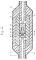
- Figure 1 shows a cross section of a preferred embodiment of the plug-in connection of two high-voltage plastic cables according to the present invention.
- Figures 2 and 3 are cross sections of other preferred embodiments of the connection of two high-voltage plastic cables according to the present invention having a closed coupling bush in the centre.
- Figure 4 shows a cross section of another embodiment of the connection of two high-voltage plastic cables according to the present invention without using a coupling bush.
- Figure 5 shows a cross-section of a right-angled embodiment of the connection of two high-voltage plastic cables according to the present invention.
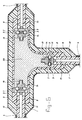
- Figure 6 shows a cross section of a right-angled embodiment of the connection of three high-voltage plastic cables according to the present invention.
- Figure 7 shows a cross section of a preferred embodiment of a connection of a high-voltage plastic cable to a high-voltage termination according to the present invention.
- Figure 8 shows a cross section of an embodiment of the connection of a high-voltage plastic cable to a high-voltage switch or high-voltage transformer according to the invention, two plugged-in cables being assembled at an arbitrarily chosen angle to the centre line of the apparatus.
- the plug-in connection for two high-voltage plastic cables comprises an elastic sleeve insulator with stress-controlling body 8, an insulating body 9 and a conducting sheath 10.
- Received in the stress-controlling body 8 is a metal coupling bush 5 whose hole is in line with the hole of the stress-controlling body 8 and the insulating body 9, as a result of which a cylindrical cavity is produced through which the cable ends 1 can be pushed as far as the inside of the coupling bush 5.
- Each cable end 1 is stripped of its earthing screen 4 over a part of its length and of the insulating sheath 12 over a shorter part.
- a plug part 14 and a counter-plug part 15 are respectively welded to the bared conductors 13.
- Both plug part 14 and counter-plug part 15 comprise a cylindrical body which fits into the cylindrical cavity inside the coupling bush.
- the plug part is provided with a projecting pin 2, while the counter-plug part is provided with a hole 16 for receiving the pin 2.
- Fitted between the pin 2 and the hole 16 are electrically conducting segments 19 for conducting the current.
- the cylindrical bodies of the plug part 14 and the counter-plug part 15 are provided with pawls 3 which can be pressed outwards by a spring 17.
- the pawls snap into annular recesses 7 in the coupling bush 5. This achieves an electrical connection and a strong mechanical coupling of the cable ends to the sleeve insulator and to each other.
- a plug pin part 14 or a counter-plug part 15 is welded to the conductor 1 of the two cable ends and the extruded earthing screen 4 is removed from the cable over a certain length of the cable end. Then one of the cable ends thus prepared in advance is inserted into the passage 11 of the sleeve insulator until the pawls 3 are pressed into the respective recess 7 of the coupling bush. Said cable conductor is then electrically and mechanically connected to coupling bush 5 and said cable end is positioned with an accuracy of ⁇ 1 mm with respect to the sleeve insulator.
- the diameter of the cable end plugged in, from which the earthing screen 4 has been removed is necessary for the diameter of the cable end plugged in, from which the earthing screen 4 has been removed, to be greater than the inside diameter of the passage 11 of the sleeve insulator so that, when the cable end is plugged into the sleeve insulator, the sleeve insulator stretches a little and lies as a close fit against the processed cable end.
- the air in the passage 11 is trapped and, without special measures, the air will build up an obstructive counter pressure if the cable end is moved further in the direction of the centre of the sleeve insulator.
- the second cable end is now plugged in so far that 1 to 2 cm of the cable insulation is situated in the passage of the sleeve insulator.
- the cable passage is sealed off from the outside air.
- the second cable end is also electrically and mechanically precisely connected to the coupling bush and a current-conducting connection between the two conductors of the cable ends is brought about because, at the same time, the plug part is plugged into the counter-plug part.
- the conducting sheath of the sleeve insulator 10 is connected in an electrically conducting manner to the earthing screen 4 of the two cables.
- the moisture-repellent and mechanical protection layers are provided over the sleeve insulator with metal earthing screen connection.
- the plugging-in of the pre-processed cable ends lasts approximately 30 minutes.
- the plug-in connection and the method according to the present invention have now been carried out a few times with a prototype of a sleeve insulator, followed by the standard type-approval tests, which have been successfully passed.
- no electrically conducting coupling bush is used.
- the plug part 14 is locked to the counter-plug part 15 with the aid of a pawl construction in which the pawls 3 and the spring 17 are situated in the plug part, while the counter-plug part is provided in this case with recesses 7 for receiving the pawls.
- Said pawl construction is fitted in a thickened part of the plug pin so that the current passage is not disturbed at the segments 19.
- Figure 5 shows a sleeve insulator according to the present invention with which a right-angled connection can be brought about.
- the coupling bush 5 is provided with a closed middle part 20 as in the embodiments according to Figures 2 and 3.
- This right-angled connection according to Figure 5 has the important advantage that use of high-voltage cables is possible in limited spaces. Space-requiring cable bends can hereby be avoided. Angles other than the right-angled connection according to Figure 5 are also obviously possible.
- connection of which the cross sections are given in Figures 1 to 4 inclusively, with another method.
- the method is as follows. A sleeve insulator in the stretched state is pushed over one of the cables. Then the electrical and mechanical coupling between the cable ends is brought about with appropriate means. If it has a space in the stress-controlling body 8 for the coupling bush 5, the sleeve insulator is then brought to the correct position around the coupled ends and the means with which the sleeve insulator has been stretched are removed. After that, the sleeve insulator fits closely onto the processed cable ends and the coupling bush 5, and the connection according to Figure 1, Figure 2, Figure 3 or Figure 4 is achieved.
- Figure 7 shows a cross section of the plug-in connection for a high-voltage plastic cable in a high-voltage outside termination.
- An elastic sleeve insulator is assembled in a mechanically strong and leak-tight manner on a metal foot plate 25 in a ground plate of the outside termination.
- said elastic sleeve insulator is identical to the sleeve insulator for connecting two high-voltage plastic cables according to Figures 1 - 5.
- the shape of the insulating body 9 is different and a part of the insulating body 9 is not provided with the conducting sheath 10.
- the end of the conducting sheath 10 is rounded off at 23. At this point, the diameter of the insulating body 9 is greater. This rounding 23 at the end of the conducting sheath 10, and the thickness and the length and conical shape of the insulating body 9 at the termination side are dimensioned at the required insulation level of the termination structure.
- connection-rod 21 of the termination insulator to the top 22 of the termination and the pre-processed cable end 1 are plugged in in the same manner as in the connection of two high-voltage cables as described above. It is also possible to test the complete termination, with porcelain insulator 24 and filling medium, with high voltage before delivery. The same quality assurance level is hereby achieved as in the connection of two high-voltage plastic cables according to the invention.
- Figure 8 shows a section of a plug-in connection for two high-voltage plastic cables in a diagrammatically shown high-voltage switch 26.
- the elastic insulator is assembled in a mechanically strong and leak-tight manner on the footplate of the diagrammatically shown switch compartment 11.
- the shape of the elastic insulator is in principle the same as the elastic insulator which is used in the outside termination of Figure 7.
- the insulator in Figure 8 is constructed in a manner such that two cables 1 can be plugged in at an angle to the axis of the breaker tank, and in practice this may be space- and cost-saving.
- the end pieces of the insulator are of identical construction as in the case of the insulator for the outside termination.
- This insulator is also tested with high voltage before delivery and the cable ends and connection rod to the current-carrying parts of the switch are plugged in using the method according to the invention.
Landscapes
- Cable Accessories (AREA)
- Details Of Connecting Devices For Male And Female Coupling (AREA)
- Connector Housings Or Holding Contact Members (AREA)
- Insulated Conductors (AREA)
- Extrusion Moulding Of Plastics Or The Like (AREA)
- Insulating Bodies (AREA)
- Steroid Compounds (AREA)
- Processing Of Terminals (AREA)
- Coupling Device And Connection With Printed Circuit (AREA)
Applications Claiming Priority (2)
| Application Number | Priority Date | Filing Date | Title |
|---|---|---|---|
| NL8901138A NL8901138A (nl) | 1989-05-03 | 1989-05-03 | Insteekverbinding voor hoogspanningskunststofkabels. |
| NL8901138 | 1989-05-03 |
Publications (2)
| Publication Number | Publication Date |
|---|---|
| EP0471032A1 EP0471032A1 (en) | 1992-02-19 |
| EP0471032B1 true EP0471032B1 (en) | 1993-08-04 |
Family
ID=19854606
Family Applications (1)
| Application Number | Title | Priority Date | Filing Date |
|---|---|---|---|
| EP90908686A Revoked EP0471032B1 (en) | 1989-05-03 | 1990-05-02 | Plug-in connection for high-voltage plastic cables |
Country Status (23)
| Country | Link |
|---|---|
| US (1) | US5316492A (cs) |
| EP (1) | EP0471032B1 (cs) |
| JP (1) | JPH04505246A (cs) |
| KR (1) | KR920700486A (cs) |
| AT (1) | ATE92678T1 (cs) |
| AU (1) | AU645495B2 (cs) |
| BR (1) | BR9007344A (cs) |
| CA (1) | CA2063582A1 (cs) |
| CS (1) | CS218090A2 (cs) |
| DD (1) | DD294376A5 (cs) |
| DE (1) | DE69002625T2 (cs) |
| DK (1) | DK0471032T3 (cs) |
| ES (1) | ES2042300T3 (cs) |
| FI (1) | FI915162A7 (cs) |
| HU (1) | HU208197B (cs) |
| IE (1) | IE66723B1 (cs) |
| NL (1) | NL8901138A (cs) |
| NO (1) | NO914305L (cs) |
| PL (1) | PL164146B1 (cs) |
| PT (1) | PT93948A (cs) |
| TR (1) | TR25622A (cs) |
| WO (1) | WO1990013933A1 (cs) |
| ZA (1) | ZA903333B (cs) |
Families Citing this family (50)
| Publication number | Priority date | Publication date | Assignee | Title |
|---|---|---|---|---|
| AU6490096A (en) * | 1995-08-31 | 1997-03-19 | Minnesota Mining And Manufacturing Company | Electrode for high voltage splices |
| IT1291526B1 (it) * | 1997-04-10 | 1999-01-11 | Pirelli Cavi S P A Ora Pirelli | Terminale secco per cavo elettrico |
| DE19733853A1 (de) * | 1997-08-05 | 1999-02-11 | Alsthom Cge Alcatel | Abzweigmuffe für elektrische Kabel |
| DE19751844C2 (de) * | 1997-11-22 | 2001-03-22 | Reinhold Barlian | Einrichtung zum Anschließen und Verbinden einer Leitung |
| DE19805068A1 (de) * | 1998-02-10 | 1999-08-12 | Abb Patent Gmbh | Kabelmuffe |
| US7677579B2 (en) * | 2002-05-31 | 2010-03-16 | Technip France Sa | Seal assembly for dividing an annular space in a double-walled pipeline |
| NL1023128C2 (nl) * | 2003-04-09 | 2004-10-18 | Lovink Enertech B V | Kabelmof. |
| DE602005006116T2 (de) | 2004-04-23 | 2009-05-07 | Shell Internationale Research Maatschappij B.V. | Verhinderung von verschorfungseffekten in bohrlöchern |
| US7435037B2 (en) | 2005-04-22 | 2008-10-14 | Shell Oil Company | Low temperature barriers with heat interceptor wells for in situ processes |
| EP2137375A4 (en) | 2007-04-20 | 2015-11-18 | Shell Int Research | IN-SITU RECONSTRUCTION OF REMAINING HEATED AREAS IN A CARBONATED FORMATION |
| US8011451B2 (en) * | 2007-10-19 | 2011-09-06 | Shell Oil Company | Ranging methods for developing wellbores in subsurface formations |
| JP5242125B2 (ja) * | 2007-10-22 | 2013-07-24 | 株式会社ビスキャス | 電力ケーブル接続部及び導体接続管 |
| US7726998B2 (en) * | 2008-07-17 | 2010-06-01 | Thomas & Betts International, Inc. | Locking pin |
| US9022118B2 (en) | 2008-10-13 | 2015-05-05 | Shell Oil Company | Double insulated heaters for treating subsurface formations |
| US8448707B2 (en) | 2009-04-10 | 2013-05-28 | Shell Oil Company | Non-conducting heater casings |
| CN102725803B (zh) * | 2009-10-09 | 2015-06-17 | 国际壳牌研究有限公司 | 用于绝缘导体的适配接头及联接方法 |
| US8257112B2 (en) | 2009-10-09 | 2012-09-04 | Shell Oil Company | Press-fit coupling joint for joining insulated conductors |
| US8356935B2 (en) * | 2009-10-09 | 2013-01-22 | Shell Oil Company | Methods for assessing a temperature in a subsurface formation |
| US9466896B2 (en) | 2009-10-09 | 2016-10-11 | Shell Oil Company | Parallelogram coupling joint for coupling insulated conductors |
| US8939207B2 (en) | 2010-04-09 | 2015-01-27 | Shell Oil Company | Insulated conductor heaters with semiconductor layers |
| US8485256B2 (en) | 2010-04-09 | 2013-07-16 | Shell Oil Company | Variable thickness insulated conductors |
| US8882548B2 (en) | 2010-10-07 | 2014-11-11 | Thomas & Betts International Llc | Cam clamp for electrical connector |
| US8943686B2 (en) | 2010-10-08 | 2015-02-03 | Shell Oil Company | Compaction of electrical insulation for joining insulated conductors |
| US8857051B2 (en) | 2010-10-08 | 2014-10-14 | Shell Oil Company | System and method for coupling lead-in conductor to insulated conductor |
| US8586866B2 (en) | 2010-10-08 | 2013-11-19 | Shell Oil Company | Hydroformed splice for insulated conductors |
| AU2010366145B2 (en) | 2010-12-22 | 2016-05-05 | Prysmian S.P.A. | Jointing assembly for electrical cables |
| JP2014512082A (ja) | 2011-04-08 | 2014-05-19 | シエル・インターナシヨナル・リサーチ・マートスハツペイ・ベー・ヴエー | 絶縁導体を接合するシステム |
| US9748722B2 (en) * | 2011-05-19 | 2017-08-29 | Prysmian S.P.A. | Terminations for electrical cables and methods for manufacturing such terminations |
| JP5925443B2 (ja) * | 2011-08-02 | 2016-05-25 | 株式会社東芝 | 静止誘導電気機器およびその製造方法 |
| JO3139B1 (ar) | 2011-10-07 | 2017-09-20 | Shell Int Research | تشكيل موصلات معزولة باستخدام خطوة اختزال أخيرة بعد المعالجة الحرارية. |
| US9080917B2 (en) | 2011-10-07 | 2015-07-14 | Shell Oil Company | System and methods for using dielectric properties of an insulated conductor in a subsurface formation to assess properties of the insulated conductor |
| JO3141B1 (ar) | 2011-10-07 | 2017-09-20 | Shell Int Research | الوصلات المتكاملة للموصلات المعزولة |
| ES2445320T3 (es) | 2011-12-21 | 2014-03-03 | 3M Innovative Properties Company | Dispositivo de conexión de terminal para un cable eléctrico |
| ES2385538A1 (es) * | 2012-03-12 | 2012-07-26 | Universidad De La Rioja | Dispositivo aislador compuesto helicoidal |
| RU2601739C2 (ru) | 2012-06-06 | 2016-11-10 | Призмиан С.П.А. | Байпасная система для воздушных линий электроснабжения |
| CA2894780C (en) | 2012-12-28 | 2019-11-12 | Prysmian S.P.A. | Container based by-pass module for electric power lines |
| US8808017B2 (en) * | 2013-01-04 | 2014-08-19 | Anderson Power Products, Inc. | Electrical connector with anti-arcing feature |
| CN105340145B (zh) | 2013-06-26 | 2019-06-18 | 3M创新有限公司 | 电力电缆端子连接装置 |
| DE102014003976A1 (de) * | 2014-03-20 | 2015-09-24 | Man Truck & Bus Ag | Verbindungsanordnung und entsprechendes Verfahren |
| CN105449620B (zh) * | 2014-07-23 | 2018-03-20 | 泰科电子(上海)有限公司 | 干式电力电缆终端 |
| US9870848B2 (en) | 2016-04-22 | 2018-01-16 | Te Connectivity Corporation | Multiple stress control device for cable accessories and methods and systems including same |
| DE102016218355A1 (de) | 2016-09-23 | 2018-03-29 | Siemens Aktiengesellschaft | Unterbrechbare Kabelmuffenanordnung |
| EP3419042A1 (en) | 2017-06-23 | 2018-12-26 | Koninklijke Philips N.V. | X-ray tube insulator |
| EP3447869B1 (en) * | 2017-08-23 | 2023-10-04 | Tyco Electronics Raychem GmbH | Electrical connector arrangement for connecting a power cable and method for installing a switchgear cabinet |
| WO2020221897A1 (en) | 2019-05-01 | 2020-11-05 | Brugg Kabel Ag | Repair and replacement of high voltage cables and joints |
| CN110197965B (zh) * | 2019-06-03 | 2024-01-19 | 核工业理化工程研究院 | 应用于30kV高压设备系统中带屏蔽和自锁功能的电连接器 |
| CN113054495A (zh) * | 2019-12-10 | 2021-06-29 | 无锡日联科技股份有限公司 | 一种小型电缆快接接头 |
| DE102021107539A1 (de) * | 2021-03-25 | 2022-09-29 | Bayerische Motoren Werke Aktiengesellschaft | Schutzeinrichtung für ein Hochvoltkabel, Hochvoltkabel, Hochvoltbordnetz sowie Kraftfahrzeug |
| CN113258505B (zh) * | 2021-05-24 | 2021-12-03 | 江苏宏达电气有限公司 | 一种电缆接头绝缘塞安装工装及安装方法 |
| CN113872141B (zh) * | 2021-09-09 | 2023-02-17 | 国网河南省电力公司孟州市供电公司 | 一种电力管道封堵器 |
Family Cites Families (15)
| Publication number | Priority date | Publication date | Assignee | Title |
|---|---|---|---|---|
| US2077737A (en) * | 1936-03-03 | 1937-04-20 | Ohio Brass Co | Cable joint |
| CH320899A (it) * | 1953-04-22 | 1957-04-15 | Pirelli | Dispositivo di giunzione di due conduttori elettrici ad alta tensione di cui uno almeno è un cavo isolato |
| NL149955B (nl) * | 1965-11-04 | 1976-06-15 | Nkf Kabel Bv | Verbinding van de aders van twee een-aderige hoogspanningskabels of de aders van twee meer-aderige hoogspanningskabels, die telkens afzonderlijk zijn doorverbonden en door een hoogspanningsmof van geleidend materiaal zijn omgeven. |
| US3612746A (en) * | 1969-02-14 | 1971-10-12 | Rte Corp | Cable-splicing device for high-voltage cables |
| CH509513A (de) * | 1969-06-20 | 1971-06-30 | Pasbrig Max | Lösbare Steckverbindungsvorrichtung |
| US3622688A (en) * | 1969-12-02 | 1971-11-23 | Rte Corp | Cable lead bushing |
| US3678432A (en) * | 1971-04-26 | 1972-07-18 | Gen Electric | Vented fuse module for underground power cable system |
| DE2130525A1 (de) * | 1971-06-16 | 1973-02-15 | Siemens Ag | Kabelmuffe fuer starkstromkabel |
| US3784729A (en) * | 1971-08-23 | 1974-01-08 | Chance Co | Electrical cable connector |
| US4074926A (en) * | 1975-05-13 | 1978-02-21 | The Scott & Fetzer Company | High voltage electrical connector |
| DE7928015U1 (de) * | 1979-09-28 | 1980-07-17 | Siemens Ag, 1000 Berlin Und 8000 Muenchen | Vorgefertigter elastischer Muffenkörper für kunststoffisolierte geschirmte Starkstromkabel |
| DK304481A (da) * | 1980-07-21 | 1982-01-22 | Bicc Ltd | Afslutning til elektrisk kabel |
| DE3124060A1 (de) * | 1981-06-18 | 1983-01-05 | Siemens AG, 1000 Berlin und 8000 München | Einpolige steckverbindung fuer starkstromkabel |
| IT1203719B (it) * | 1983-12-27 | 1989-02-23 | Pirelli Cavi Spa | Procedimento e dispositivo per realizzare giunti per cavi |
| US4586774A (en) * | 1984-04-23 | 1986-05-06 | Biw Cable Systems, Inc. | Electrical connector for armored cables |
-
1989
- 1989-05-03 NL NL8901138A patent/NL8901138A/nl active Search and Examination
-
1990
- 1990-05-02 BR BR909007344A patent/BR9007344A/pt not_active IP Right Cessation
- 1990-05-02 DD DD90340308A patent/DD294376A5/de not_active IP Right Cessation
- 1990-05-02 AT AT90908686T patent/ATE92678T1/de active
- 1990-05-02 JP JP2508072A patent/JPH04505246A/ja active Pending
- 1990-05-02 WO PCT/NL1990/000060 patent/WO1990013933A1/en not_active Ceased
- 1990-05-02 AU AU56707/90A patent/AU645495B2/en not_active Ceased
- 1990-05-02 KR KR1019900702703A patent/KR920700486A/ko not_active Ceased
- 1990-05-02 HU HU905262A patent/HU208197B/hu not_active IP Right Cessation
- 1990-05-02 ZA ZA903333A patent/ZA903333B/xx unknown
- 1990-05-02 US US07/772,357 patent/US5316492A/en not_active Expired - Fee Related
- 1990-05-02 ES ES199090908686T patent/ES2042300T3/es not_active Expired - Lifetime
- 1990-05-02 EP EP90908686A patent/EP0471032B1/en not_active Revoked
- 1990-05-02 PL PL90285042A patent/PL164146B1/pl unknown
- 1990-05-02 FI FI915162A patent/FI915162A7/fi not_active Application Discontinuation
- 1990-05-02 CS CS902180A patent/CS218090A2/cs unknown
- 1990-05-02 IE IE160690A patent/IE66723B1/en not_active IP Right Cessation
- 1990-05-02 DK DK90908686.0T patent/DK0471032T3/da active
- 1990-05-02 CA CA002063582A patent/CA2063582A1/en not_active Abandoned
- 1990-05-02 DE DE90908686T patent/DE69002625T2/de not_active Revoked
- 1990-05-03 PT PT93948A patent/PT93948A/pt not_active Application Discontinuation
- 1990-05-03 TR TR90/0430A patent/TR25622A/xx unknown
-
1991
- 1991-11-01 NO NO91914305A patent/NO914305L/no unknown
Also Published As
| Publication number | Publication date |
|---|---|
| NO914305D0 (no) | 1991-11-01 |
| IE901606L (en) | 1990-11-03 |
| CS218090A2 (en) | 1991-09-15 |
| AU645495B2 (en) | 1994-01-20 |
| WO1990013933A1 (en) | 1990-11-15 |
| EP0471032A1 (en) | 1992-02-19 |
| US5316492A (en) | 1994-05-31 |
| ATE92678T1 (de) | 1993-08-15 |
| BR9007344A (pt) | 1992-04-28 |
| PL164146B1 (pl) | 1994-06-30 |
| JPH04505246A (ja) | 1992-09-10 |
| TR25622A (tr) | 1993-07-01 |
| PT93948A (pt) | 1991-11-29 |
| HU208197B (en) | 1993-08-30 |
| FI915162A0 (fi) | 1991-11-01 |
| HU905262D0 (en) | 1992-04-28 |
| DK0471032T3 (da) | 1994-01-03 |
| NO914305L (no) | 1991-11-01 |
| ES2042300T3 (es) | 1993-12-01 |
| DE69002625D1 (de) | 1993-09-09 |
| ZA903333B (en) | 1991-02-27 |
| HUT60071A (en) | 1992-07-28 |
| KR920700486A (ko) | 1992-02-19 |
| FI915162A7 (fi) | 1991-11-01 |
| AU5670790A (en) | 1990-11-29 |
| CA2063582A1 (en) | 1990-11-04 |
| IE66723B1 (en) | 1996-01-24 |
| DD294376A5 (de) | 1991-09-26 |
| NL8901138A (nl) | 1990-12-03 |
| DE69002625T2 (de) | 1994-01-05 |
Similar Documents
| Publication | Publication Date | Title |
|---|---|---|
| US5316492A (en) | Plug-in connection for high-voltage plastic cable | |
| US6227908B1 (en) | Electric connection | |
| EP0731994B2 (en) | Cable termination | |
| US3800064A (en) | Universal power cable joint with closed-cell sponge stress relief element | |
| US5052946A (en) | Plug connector for high-voltage coaxial cables | |
| US6452102B1 (en) | High voltage cable termination | |
| US3602872A (en) | Electrical connector for tapping shielded high voltage cable | |
| EP0087267B1 (en) | An electrical high-voltage connector and connection assembly | |
| US3585568A (en) | Splice cover and cplice assembly | |
| EP3062399A1 (en) | Multi-piece jacket for separable connectors | |
| EP0510019B1 (en) | Cable connector | |
| US3853375A (en) | Electrical connector apparatus disconnectable link assembly | |
| US3692921A (en) | Cable coupler | |
| ES291606U (es) | Conector para cables electricos aislados | |
| US20240405537A1 (en) | Termination for a cable for transporting high-voltage or very-high-voltage electricity, and method for preparing a cable end termination | |
| US3344382A (en) | Transformer with secondary terminal and clustered service conductors | |
| US3431539A (en) | Cable junction | |
| EP4054027A1 (en) | Electric power cable connector arrangement | |
| GB2354374A (en) | Cable joint insert block with insulation displacement contacts | |
| HK1226870A1 (en) | Multi-piece jacket for separable connectors | |
| MXPA96001998A (en) | Head or termination of ca |
Legal Events
| Date | Code | Title | Description |
|---|---|---|---|
| PUAI | Public reference made under article 153(3) epc to a published international application that has entered the european phase |
Free format text: ORIGINAL CODE: 0009012 |
|
| 17P | Request for examination filed |
Effective date: 19911101 |
|
| AK | Designated contracting states |
Kind code of ref document: A1 Designated state(s): AT BE CH DE DK ES FR GB IT LI LU NL SE |
|
| 17Q | First examination report despatched |
Effective date: 19921106 |
|
| GRAA | (expected) grant |
Free format text: ORIGINAL CODE: 0009210 |
|
| AK | Designated contracting states |
Kind code of ref document: B1 Designated state(s): AT BE CH DE DK ES FR GB IT LI LU NL SE |
|
| REF | Corresponds to: |
Ref document number: 92678 Country of ref document: AT Date of ref document: 19930815 Kind code of ref document: T |
|
| ITF | It: translation for a ep patent filed | ||
| REF | Corresponds to: |
Ref document number: 69002625 Country of ref document: DE Date of ref document: 19930909 |
|
| ET | Fr: translation filed | ||
| REG | Reference to a national code |
Ref country code: ES Ref legal event code: FG2A Ref document number: 2042300 Country of ref document: ES Kind code of ref document: T3 |
|
| REG | Reference to a national code |
Ref country code: DK Ref legal event code: T3 |
|
| PLBI | Opposition filed |
Free format text: ORIGINAL CODE: 0009260 |
|
| PLBI | Opposition filed |
Free format text: ORIGINAL CODE: 0009260 |
|
| 26 | Opposition filed |
Opponent name: SIEMENS AG Effective date: 19940429 |
|
| 26 | Opposition filed |
Opponent name: KABELMETAL ELECTRO GMBH Effective date: 19940502 Opponent name: SIEMENS AG Effective date: 19940429 |
|
| EPTA | Lu: last paid annual fee | ||
| NLR1 | Nl: opposition has been filed with the epo |
Opponent name: SIEMENS AG. |
|
| NLR1 | Nl: opposition has been filed with the epo |
Opponent name: KABELMETAL ELECTRO GMBH |
|
| EAL | Se: european patent in force in sweden |
Ref document number: 90908686.0 |
|
| PGFP | Annual fee paid to national office [announced via postgrant information from national office to epo] |
Ref country code: GB Payment date: 19960422 Year of fee payment: 7 |
|
| PGFP | Annual fee paid to national office [announced via postgrant information from national office to epo] |
Ref country code: LU Payment date: 19960501 Year of fee payment: 7 |
|
| PGFP | Annual fee paid to national office [announced via postgrant information from national office to epo] |
Ref country code: FR Payment date: 19960506 Year of fee payment: 7 |
|
| PGFP | Annual fee paid to national office [announced via postgrant information from national office to epo] |
Ref country code: ES Payment date: 19960509 Year of fee payment: 7 |
|
| PGFP | Annual fee paid to national office [announced via postgrant information from national office to epo] |
Ref country code: SE Payment date: 19960510 Year of fee payment: 7 Ref country code: DK Payment date: 19960510 Year of fee payment: 7 Ref country code: BE Payment date: 19960510 Year of fee payment: 7 Ref country code: AT Payment date: 19960510 Year of fee payment: 7 |
|
| PGFP | Annual fee paid to national office [announced via postgrant information from national office to epo] |
Ref country code: NL Payment date: 19960531 Year of fee payment: 7 |
|
| PGFP | Annual fee paid to national office [announced via postgrant information from national office to epo] |
Ref country code: CH Payment date: 19960621 Year of fee payment: 7 |
|
| PGFP | Annual fee paid to national office [announced via postgrant information from national office to epo] |
Ref country code: DE Payment date: 19960626 Year of fee payment: 7 |
|
| RDAH | Patent revoked |
Free format text: ORIGINAL CODE: EPIDOS REVO |
|
| REG | Reference to a national code |
Ref country code: DK Ref legal event code: EBP |
|
| RDAG | Patent revoked |
Free format text: ORIGINAL CODE: 0009271 |
|
| STAA | Information on the status of an ep patent application or granted ep patent |
Free format text: STATUS: PATENT REVOKED |
|
| REG | Reference to a national code |
Ref country code: CH Ref legal event code: PL |
|
| GBPR | Gb: patent revoked under art. 102 of the ep convention designating the uk as contracting state |
Free format text: 961117 |
|
| 27W | Patent revoked |
Effective date: 19961117 |
|
| NLR2 | Nl: decision of opposition |